2003 LEXUS LS430 ECO mode
[x] Cancel search: ECO modePage 231 of 4500

IG - GND (A11-9
- A11-1)LG-R -
W-BPower source (IG)Ignition switch OFF.0 V
TSDr - GND
(A11-19 - A11-1)L - W-BSolar sensor signal (Driver
side)Ignition switch ON. Solar sensor
subjected to electric light.0.8 to 4.3 V
TSDr - GND
(A11-19 - A11-1)L - W-BSolar sensor signal (Driver
side)Ignition switch ON. Solar sensor
covered by a cloth.Below 0.8 V
TSPa - GND
(A11-20 - A11-1)G-R - W-
BSolar sensor signal
(Passenger side)Ignition switch ON. Solar sensor
subjected to electric light.0.8 to 4.3 V
TSPa - GND
(A11-20 - A11-1)G-R - W-
BSolar sensor signal
(Passenger side)Ignition switch ON. Solar sensor
covered by a cloth.Below 0.8 V
+B - GND (A11-
21 - A11-1)B-Y - W-
BPower source (Back-up)Always10 to 14 V
DGS - SG-1
(A11-29 - A13-8)B - YExhaust gas sensor signal
After 30 seconds from Ignition
switch ON and the sensor is
exposed to the exhaust gas.
1.0 to 4.5 V
DS1 - GND
(A12-1 - A11-1)V - W-BSwing grill STEP motor
signal
Ignition switch ON. Blower
motor: Operating Mode selector:
BI-LEVEL Intelligent swing
register: ON
Pulse
generation
Symbols
(Terminal No.)Wiring
colorTerminal DescriptionConditionSpecification
DS2 - GND
(A12-2 - A11-1)G - W-BSwing grill STEP motor
signal
Ignition switch ON. Blower
motor: Operating Mode selector:
BI-LEVEL Intelligent swing
register: ON
Pulse
generation
PS1 - GND (A12-
3 - A11-1)R-B - W-
BSwing grill STEP motor
signal
Ignition switch ON. Blower
motor: Operating Mode selector:
BI-LEVEL Intelligent swing
register: ON
Pulse
generation
PS2 - GND (A12-
4 - A11-1)B - W-BSwing grill STEP motor
signal
Ignition switch ON. Blower
motor: Operating Mode selector:
BI-LEVEL Intelligent swing
register: ON
Pulse
generation
PS3 - GND (A12-
5 - A11-1)P - W-BSwing grill STEP motor
signal
Ignition switch ON. Blower
motor: Operating Mode selector:
BI-LEVEL Intelligent swing
register: ON
Pulse
generation
PS4 - GND (A12-
6 - A11-1)Y-R - W-
BSwing grill STEP motor
signal
Ignition switch ON. Blower
motor: Operating Mode selector:
BI-LEVEL Intelligent swing
register: ON
Pulse
generation
DUAL - DrGND
(A12-7 - A12-11)O - LG-RDual temperature control
signalIgnition switch ON. Dual switch
ON.Below 1.0 V
DUAL - DrGND
(A12-7 - A12-11)O - LG-RDual temperature control
signalIgnition switch ON. Dual switch
OFF.10 to 14 V
Page 233 of 4500

12)side)switch ON.
DrDN - DrGND
(A12-21 - A12-
11)P-L - LG-
RTemperature control
switch signal (Driver side)Push driver temperature switch
OFF.10 to 14 V
DrDN - DrGND
(A12-21 - A12-
11)P-L - LG-
RTemperature control
switch signal (Driver side)Push driver temperature switch
ON.Below 1.0 V
DrUP - DrGND
(A12-22 - A12-
11)V-W -
LG-RTemperature control
switch signal (Driver side)Push driver temperature switch
OFF.10 to 14 V
DrUP - DrGND
(A12-22 - A12-
11)V-W -
LG-RTemperature control
switch signal (Driver side)Push driver temperature switch
ON.Below 1.0 V
PS+B - GND
(A12-24 - A11-1)R-G - W-
BSwing grill STEP motor
operation voltageAlways10 to 14 V
TFACEPa - SG-4
(A13-14 - A13-
11)B-Y - Y-
GDuct sensor signal
(Passenger side)Ignition switch ON. Passenger
side duct sensor temperature 25 °
C (77 °F).
1.8 to 2.2 V
TFACEPa - SG-4
(A13-14 - A13-
11)B-Y - Y-
GDuct sensor signal
(Passenger side)Ignition switch ON. Passenger
side duct sensor temperature 50 °
C (122 °F).
0.8 to 1.2 V
TFACEDr - SG-3
(A13-15 - A13-
10)GR-R -
R-WDuct sensor signal (Driver
side)Ignition switch ON. Passenger
side duct sensor temperature 25 °
C (77 °F).
1.8 to 2.2 V
TFACEDr - SG-3
(A13-15 - A13-
10)GR-R -
R-WDuct sensor signal (Driver
side)Ignition switch ON. Passenger
side duct sensor temperature 50 °
C (122 °F).
0.8 to 1.2 V
TR - SG-2 (A13-
16 - A13-9)W-L - Y-
BRoom temperature sensor
signalIgnition switch ON. Room
temperature 25 °C (77°F).1.8 to 2.2 V
TR - SG-2 (A13-
16 - A13-9)W-L - Y-
BRoom temperature sensor
signalIgnition switch ON. Room
temperature 40 °C (104°F).0.8 to 1.2 V
NOX - Body
ground (A13-17 -
Body ground)L-B -
Body
ground
Exhaust gas sensor signal
After 120 seconds from Ignition
switch ON and the sensor is
exposed to the exhaust gas.
1.0 to 4.5 V
AMDr1 - GND
(A37-1 - A11-1)BR - W-B
Air mix servomotor
operation signal (Driver
side)During actuator check mode.
Change display code 0 to display
code 9.Pulse
generation
AMDr2 - GND
(A37-2 - A11-1)BR-B -
W-BAir mix servomotor
operation signal (Driver
side)During actuator check mode.
Change display code 0 to display
code 9.Pulse
generation
AMDr3 - GND
(A37-3 - A11-1)BR-W -
W-BAir mix servomotor
operation signal (Driver
side)During actuator check mode.
Change display code 0 to display
code 9.Pulse
generation
AMDr4 - GND
(A37-4 - A11-1)BR-Y -
W-BAir mix servomotor
operation signal (Driver During actuator check mode.
Change display code 0 to display Pulse
generation
Page 241 of 4500

1.STEP MOTORS INITIALIZING FUNCTION
STEP motor initializing procedure (Automatic initializing)
1. When the battery is reconnected and the ignition switch is turned to the ON position for the first
time, the initializing function of the STEP motors is activated. In this case, the "FRONT DEF"
indicator blinks.
SET TEMP SHIFT
(Set Temperature
Shift)
NORMALTo control with the shifted temperature
against the display temperature.+2C/+1C/ NORMAL -
1C / -2C
AIR INLET MODE
(Air Inlet Mode)AUTO
In case of turning the A/C ON when you
desire to make the compartment cool down
quickly, this is the function to change the
mode automatically to RECIRCULATED
mode.
MANUAL / AUTO
COMPRESSOR
MODE (Compressor
Mode)
AUTO
Function to turn the A/C ON automatically
by pressing the AUTO button when the
blower is ON and the A/C is OFF.
MANUAL / AUTO
COMPRS/DEF OPER
(Compressor/Air Inlet
DEF Operation)
LINK
Function to turn the A/C ON automatically
linking with the FRONT DEF button when
A/C is OFF.
NORMAL / LINK
MOTOR INITIALIZ
(STEP Motor
Initializing (IG/off))
OFFFunction to initialize the STEP motor after
the ignition switch is OFF.ON / OFF
EVAP CTRL
(External Variable
Control OFF)
AUTO
Function to set the evaporator control to the
AUTOMATIC position (AUTO) to save
power or to the coldest position
(MANUAL) to dehumidify the air and to
prevent the windows from fogging up.
MANUAL / AUTO
GAS SENS SHIFT
(Shift Emission Gas
Sensor Sensitivity)
NORMALFunction to change the sensitivity of the
exhaust gas sensor.
MU MORE /MORE / LI
MORE / NORMAL / LI
LESS / LESS / MU
LESS
AUTO MODE
(Cancel Auto Mode)AUTOFunction to swing the vent vans
automatically when A/C is ON.MANUAL / AUTO
BUTTON PRS BUS
(Cancel Operating
Switch Sound)
ONFunction to sound a buzzer when a button
is pressed.OFF / ON
FILTER SENS (Shift
Filter Clog Sensitivity)NORMALFunction to change the sensitivity of the air
conditioning filter choking sensor.LESS / NORMAL /
MORE
FOOT AIR LEAK
(Cancel Air Outlet
Foot II)
ONFunction to cut off the airstream felt
underfoot while the vehicle is moving.OFF / ON
Page 477 of 4500

Fig. 6: Connecting Hand-Held Tester To DLC3
Courtesy of TOYOTA MOTOR SALES, U.S.A., INC.
TEST MODE
HINT:
In step (6), all signals can be checked together.
Check ItemOperation (A)Operation (B)
Height control switchNORM
positionHIGH position
Absorber control
switch-Slowly move the absorber control switch "NORM"
<--> "SPORT" both ways once
Right front acceleration
sensor-Keep the vehicle still without any vertical
movement for 1 second
Left front acceleration
sensor-Keep the vehicle still without any vertical
movement for 1 second
Rear acceleration
sensor-Keep the vehicle still without any vertical
movement for 1 second
Page 486 of 4500

Fig. 11: Identifying Absorber Control Indicator Lamp Location (1 Of 2)
Courtesy of TOYOTA MOTOR SALES, U.S.A., INC.
d. DTCs (Normal mode)
1. DTCs are memorized in the suspension control ECU and read by using the hand-held tester
(SEE DTC CHECK/CLEAR
for the procedure of DTCs check).
e. Test mode
1. By switching from normal mode into test mode, you can inspect the height control switch,
absorber control switch, front acceleration sensor and rear acceleration sensor (SEE TEST
MODE PROCEDURE ).
2.CHECK INDICATOR LAMP
1. Turn the ignition switch to the ON position.
2. Check that the absorber control indicator lamp comes on for 2 seconds.
If the indicator check result is not normal, proceed to troubleshooting for the indicator lamp circuit.
TROUBLE AREA REFERENCE
Trouble AreaSee Procedure
Absorber control indicator lamp ABSORBER CONTROL INDICATOR LAMP
Page 723 of 4500

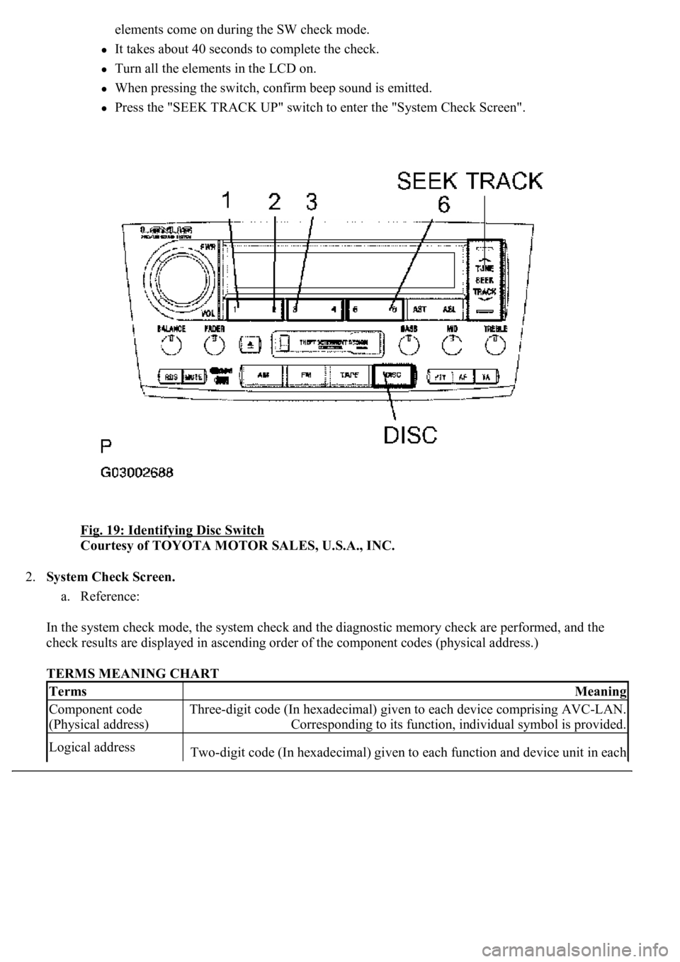
elements come on during the SW check mode.
It takes about 40 seconds to complete the check.
Turn all the elements in the LCD on.
When pressing the switch, confirm beep sound is emitted.
Press the "SEEK TRACK UP" switch to enter the "System Check Screen".
Fig. 19: Identifying Disc Switch
Courtesy of TOYOTA MOTOR SALES, U.S.A., INC.
2.System Check Screen.
a. Reference:
In the system check mode, the system check and the diagnostic memory check are performed, and the
check results are displayed in ascending order of the component codes (physical address.)
TERMS MEANING CHART
TermsMeaning
Component code
(Physical address)Three-digit code (In hexadecimal) given to each device comprising AVC-LAN.
Corresponding to its function, individual symbol is provided.
Logical addressTwo-digit code (In hexadecimal) given to each function and device unit in each
Page 724 of 4500

3.Finishing Diagnostic Mode.
a. Press the "DISC" for 2 seconds or more, or turn the ignition switch off.
HINT:
Illustrations may differ from the actual vehicle depending on the device settings and options. Therefore, some
detailed areas may not be shown exactly the same as on the actual vehicle.
1.Start the diagnostic mode (SEE DIAGNOSTIC START
-UP/FINISH ).
2.Read the system check result.
1. Press the "SEEK TRACK" switch to see the check result of each component.
2. The component device code (physical address) is displayed first, and then the check result follows.
HINT:
If all check results are "good" the system judges that no DTC exists.
device comprising AVC-LAN
Page 728 of 4500

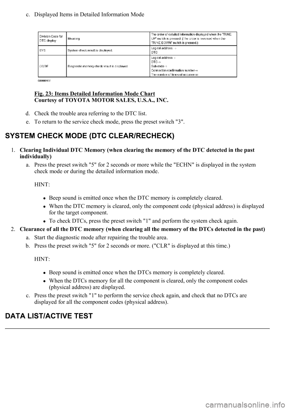
c. Displayed Items in Detailed Information Mode
Fig. 23: Items Detailed Information Mode Chart
Courtesy of TOYOTA MOTOR SALES, U.S.A., INC.
d. Check the trouble area referring to the DTC list.
e. To return to the service check mode, press the preset switch "3".
1.Clearing Individual DTC Memory (when clearing the memory of the DTC detected in the past
individually)
a. Press the preset switch "5" for 2 seconds or more while the "ECHN" is displayed in the system
check mode or during the detailed information mode.
HINT:
Beep sound is emitted once when the DTC memory is completely cleared.
When the DTC memory is cleared, only the component code (physical address) is displayed
for the target component.
To check DTCs, press the preset switch "1" and perform the system check again.
2.<0026004f004800440055004400510046004800030052004900030044004f004f00030057004b00480003002700370026000300500048005000520055005c0003000b005a004b0048005100030046004f004800440055004c0051004a00030044004f004f00
030057004b0048000300500048005000520055005c00030052[f the DTCs detected in the past)
a. Start the diagnostic mode after repairing the trouble area.
b. Press the preset switch "5" for 2 seconds or more. ("CLR" is displayed at this time.)
HINT:
Beep sound is emitted once when the DTCs memory is completely cleared.
When the DTCs memory for all the component is cleared, only the component codes
(physical address) are displayed.
c. Press the preset switch "1" to perform the service check again, and check that no DTCs are
displayed for all the component codes (physical address).