Page 806 of 4500
In AVC-LAN, radio receiver assy becomes the communication master, and the radio receiver assy has enough
resistance necessary for transmitting the communication.
WIRING DIAGRAM
Fig. 88: Identifying Stereo Component Amplifier Assy
- Audio And Rear A/C Control SW Wiring
Diagram
Courtesy of TOYOTA MOTOR SALES, U.S.A., INC.
INSPECTION PROCEDURE
1.CHECK HARNESS AND CONNECTOR (STEREO COMPONENT AMPLIFIER ASSY - AUDIO
AND REAR A/C CONTROL SW)
a. Disconnect the connector from the stereo component amplifier assy S29 and audio and rear A/C
control SW A35.
b. Measure the resistance according to the value (s) in the table below.
Standard:
TESTER CONNECTION CONDITION CHART
Tester connectionConditionSpecified condition
TX+ - TXD+(1), RTX+(2)AlwaysBelow 1 ohms
TX- - TXD-(1), RTX-(2)AlwaysBelow 1 ohms
TX+ - Body groundAlways10 kohms or higher
TX- - Body groundAlways10 kohms or higher
(1)Mark Levinson Models
(2)Standard Models
Page 1077 of 4500
1.CONNECT HAND-HELD TESTER:
a. Connect the hand-held tester to the DLC3.
b. Start the engine and run at idle.
c. Select the ACTIVE TEST mode on the hand-held tester.
HINT:
Please refer to the hand-held tester operators manual for further details.
Fig. 109: Connecting Hand
-Held Tester To DLC3
Courtesy of TOYOTA MOTOR SALES, U.S.A., INC.
2.INSPECT ACTUATOR MOTOR OPERATION
a. With the motor relay on, check the actuator motor operation noise.
b. Turn the motor relay off.
c. Depress the brake pedal and hold it for approximately 15 seconds. Check that the brake pedal
cannot be depressed.
d. With the motor rela
y on, check that the pedal does not pulsate.
Page 1515 of 4500
c. After turning the ignition switch to the ON position, wait for 2 seconds or more, then turn the
clearance sonar main switch on. Check the multi-information display and the buzzer sounding
condition.
Standard:
After the main switch is turned on, the multi-information display shows the Fig. 9
below
for approximatel
y 2 seconds and the buzzer sounds for approximately 1 second then the
detection mode begins.
Fig. 9: Identifying Multi
-Information Display
Courtesy of TOYOTA MOTOR SALES, U.S.A., INC.
HINT:
Multi-information display:
The malfunctioning sensor blinks on the display when the wire harness or the connector is
faulty and requires repair or replacement, or when trouble is detected in the ultrasonic sensor
circuits. After the sensor operation returns to normal, the detection mode will finish
normall
y.
Page 1591 of 4500
COMMUNICATION
1.GENERAL
The climate control seat system creates cold or warm air to increase the comfort of seats that have
become hot or cold.
The air is heated or cooled by the Peltier element on the back of the seat cushion pad and seatback. The
air is then sent to the seat cushion and seatback with the fan installed under the seat. The fan is operated
by pressing the climate control seat switch.
The climate control seat switch has several modes that vary the quantity of air to be sent to the seat. There
are 7 modes in total: 3 cooled air modes, 3 heated air modes and ventilation mode.
HINT:
When the highest level for cooled air operates for 15 minutes, the quantity of air falls 1 level.
2.FUNCTION OF MAIN COMPONENT
Fig. 4: Main Component Function Table
Courtesy of TOYOTA MOTOR SALES, U.S.A., INC.
3.SYSTEM OPERATION
SenderReceiverSignalLine
Climate control ECUECMIdle-up signalBEAN (Door bus), CAN
Page 1750 of 4500

INSPECTION ).
b. Computer area
The items from "Range Over ***/Range Approx ***" to "BLANK" can be changed with the
DISP1 (switch) of the steering pad switch.
c. Graphic area
Open Door Display:
<0037004b004800030047004c00560053004f0044005c0003004c005600030056004b0052005a00510003005a004b00480051000300440051005c00030052004900030057004b00480003004700520052005500560003004400550048000300520053004800
51005600110003[
HINT:
If the warning item other than the door warning is detected at the same time, the master warning
comes on/blinks in accordance to direction from the displayed item in the warning area.
Park Sonar Display:
See HOW TO PROCEED WITH TROUBLESHOOTING for details on the park sonar display.
The display blinks when the clearance is the closest.
Others:
The items "COMPASS", "OUTSIDE TEMPERATURE" and "BLANK" can be changed with the
DISP2 (switch) of the steering pad switch.
While +B is connected, the mode that was on when the ignition switch was turned off the last time
is displayed.
When the display is changed from radar cruise, it is displayed for only 6 seconds and then returns
to the radar cruise display.
While the radar cruise is on, "RADAR CRUISE READY" is displayed in the warning area if the
park sonar and door open displays are in the graphic area.
Radar Cruise Display:
See HOW TO PROCEED WITH TROUBLESHOOTING for details on the radar cruise
display.
The radar cruise set display is interrupted for only 6 seconds while the park sonar and/or open door
(displays) are on.
<0037004b004800030047004c00560053004f0044005c000300450055004c0051004e00560003005a004b004800510003005a004400550051004c0051004a00030057004b0048000300470055004c00590048005500030057004b0044005700030057004b00
4800030047004c0056005700440051004600480003005a004c[th other vehicles is getting to be too
close. This warning has priority over all.
1.VEHICLE BROUGHT TO WORKSHOP
2.(SEE CUSTOMER PROBLEM ANALYSIS CHECK
)
3.PROBLEM SYMPTOM CONFIRMATION (SEE PROBLEM SYMPTOMS TABLE
)
4.CHECK MULTIPLEX COMMUNICATION SYSTEM (SEE HOW TO PROCEED WITH
TROUBLESHOOTING )
a. Check for DTC outputs
Page 1753 of 4500

The followings are the possible items to be customized.
ILLUMINATED ENTRY:
Fig. 17: Customize Parameters Reference Chart
Courtesy of TOYOTA MOTOR SALES, U.S.A., INC.
1.SELECTING COMPASS DISPLAY MODE
The "DISP2" of the steering pad switch allows you to select a Display or Non-display mode of the
compass.
2.SETTING ZONE
Deviation between the magnetic north and "actual north" differs depending on the terrestrial location,
therefore, an adjustment in magnetism is required. Since the magnetic condition differs according to the
area where the vehicle will be used, it is necessary for each user to set the zone. (Refer to "Compass Zone
Map"). The zone setting can be changed using the hand-held tester.
3.PERFORMING CALIBRATION
Because each vehicle has its own magnetic field, calibration should be performed for each vehicle. This
compass function is used when storing the record of the vehicle's magnetic field.
4.WHEN COMPASS MAGNETIZED:
A compass could be magnetized during shipping by vessels or freight cars. Before delivery, therefore,
make sure to perform calibration and ensure that calibration can be done. If it cannot be done (cannot
complete in spite of driving round several times), it may be caused by magnetization. Demagnetize the
vehicle usin
g a demagnetizer and perform calibration again.
Page 1776 of 4500

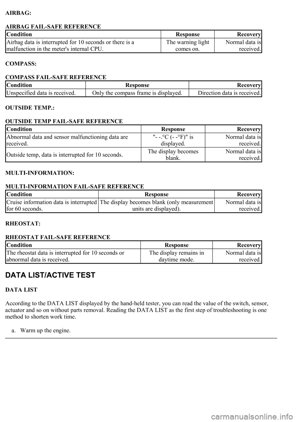
AIRBAG:
AIRBAG FAIL-SAFE REFERENCE
COMPASS:
COMPASS FAIL-SAFE REFERENCE
OUTSIDE TEMP.:
OUTSIDE TEMP FAIL-SAFE REFERENCE
MULTI-INFORMATION:
MULTI-INFORMATION FAIL-SAFE REFERENCE
RHEOSTAT:
RHEOSTAT FAIL-SAFE REFERENCE
DATA LIST
According to the DATA LIST displayed by the hand-held tester, you can read the value of the switch, sensor,
actuator and so on without parts removal. Reading the DATA LIST as the first step of troubleshooting is one
method to shorten work time.
a. Warm up the en
gine.
ConditionResponseRecovery
Airbag data is interrupted for 10 seconds or there is a
malfunction in the meter's internal CPU.The warning light
comes on.Normal data is
received.
ConditionResponseRecovery
Unspecified data is received.Only the compass frame is displayed.Direction data is received.
ConditionResponseRecovery
Abnormal data and sensor malfunctioning data are
received."- -.°C (- -°F)" is
displayed.Normal data is
received.
Outside temp, data is interrupted for 10 seconds.The display becomes
blank.Normal data is
received.
ConditionResponseRecovery
Cruise information data is interrupted
for 60 seconds.The display becomes blank (only measurement
units are displayed).Normal data is
received.
ConditionResponseRecovery
<0037004b004800030055004b004800520056005700440057000300470044005700440003004c00560003004c005100570048005500550058005300570048004700030049005200550003001400130003005600480046005200510047005600030052005500
03[
abnormal data is received.The display remains in
daytime mode.Normal data is
received.
Page 1848 of 4500

Standard:
Float down (switch on): Below 1 ohms
f. Pour the fluid back in the reservoir tank.
9.INSPECT WASHER LEVEL WARNING SWITCH
a. Disconnect the connector from the washer level warning switch.
b. Turn the ignition switch to the ON position.
c. Ground the terminal of the wire harness side connector, then check the washer level warning light.
OK:
Washer level warning light comes on.
10.MAINTENANCE LIQUID RESETTING PROCEDURE
a. Check that the display for ODO/TRIP shows no value (BLANK).
b. Turn the ignition switch off.
c. Pressing the reset switch, turn the ignition switch to the ON (keep pressing at least for 5 seconds).
d. The reset procedure is completed.
HINT:
During reset procedure:
"Mileage Reset" is displayed and the master warning light comes on with a buzzer sound.
Completion of reset procedure:
"Mileage Reset" and the master warning light go off.
If the ignition switch is turned off during reset procedure, reset mode is canceled.
If the reset switch is turned off during the reset procedure, reset mode is canceled and the display
shows the condition prior to the reset procedure.
If "Maint Reqd Soon" is displayed, it goes off 15 seconds after turning the ignition switch to the
ON position.