Page 2547 of 4500
Fig. 15: Identifying Cruise Control Main Switch
Courtesy of TOYOTA MOTOR SALES, U.S.A., INC.
2.INSPECT MODE SWITCH
a. Turn the ignition switch to the ON position.
HINT:
Dynamic radar cruise system is in the default mode.
b. After pushing the ON-OFF button on, push the cruise control main switch to MODE for at least 1
second without any other control. Make sure that only "NORM." and nothing else is indicated on
the display.
Page 2716 of 4500
Fig. 37: Connecting Hand Held Tester To DLC3
Courtesy of TOYOTA MOTOR SALES, U.S.A., INC.
Turn the ignition switch OFF after the symptom is simulated once. Then repeat the simulation process
again. When the problem has been simulated twice, the MIL illuminates and the DTCs are recorded in the
ECM.
2.CLEAR DTC
a. Connect the hand-held tester to the CAN VIM. Then connect the CAN VIM to the DLC3.
b. Turn the ignition switch ON.
c. Enter the following menus: DIAGNOSIS/ ENHANCED OBD II/ DTC INFO/ CLEAR CODES and
press YES.
CHECK MODE PROCEDURE
DESCRIPTION
Page 2913 of 4500
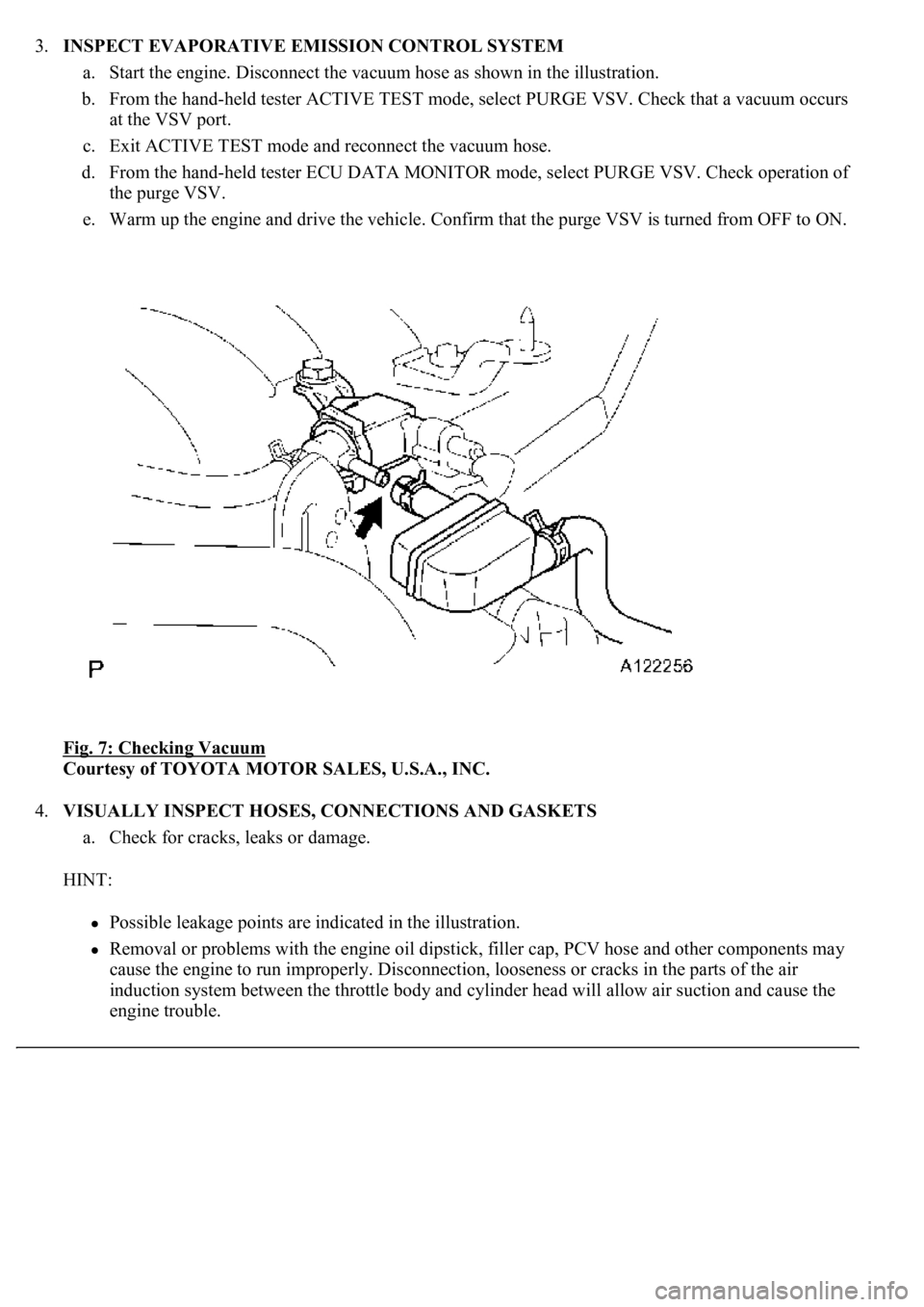
3.INSPECT EVAPORATIVE EMISSION CONTROL SYSTEM
a. Start the engine. Disconnect the vacuum hose as shown in the illustration.
b. From the hand-held tester ACTIVE TEST mode, select PURGE VSV. Check that a vacuum occurs
at the VSV port.
c. Exit ACTIVE TEST mode and reconnect the vacuum hose.
d. From the hand-held tester ECU DATA MONITOR mode, select PURGE VSV. Check operation of
the purge VSV.
e. Warm up the engine and drive the vehicle. Confirm that the purge VSV is turned from OFF to ON.
Fig. 7: Checking Vacuum
Courtesy of TOYOTA MOTOR SALES, U.S.A., INC.
4.VISUALLY INSPECT HOSES, CONNECTIONS AND GASKETS
a. Check for cracks, leaks or damage.
HINT:
Possible leakage points are indicated in the illustration.
Removal or problems with the engine oil dipstick, filler cap, PCV hose and other components may
cause the engine to run improperly. Disconnection, looseness or cracks in the parts of the air
induction system between the throttle body and cylinder head will allow air suction and cause the
engine trouble.
Page 3167 of 4500
3.SYSTEM FUNCTION
When the steering lock ECU detects that the unlock warning switch is ON, the ECU provides current to
the transponder key coil and produces a faint electric wave. A transponder chip in the key and receives
the faint electric wave. Upon receiving the faint electric wave, the transponder chip outputs a key ID code
signal. The transponder key coil receives this signal, the transponder key amplifier amplifies it, and then
the signal is transmitted to the ECU.
The ECU matches the key's ID code with the vehicle's ID code, which was previously registered in the
ECU and then communicates the results to the ECM using SFI communication.
After the identification results show that the key's ID code matches the vehicle's ID code and the ECU has
confirmed their match: 1) the immobilizer system does not immobilize the engine and the engine starting
controls (fuel injection control and ignition control) enter standby mode; and 2) the ECU transmits a
security indicator signal that communicates "indicator off" to the theft warning ECU (theft deterrent
ECU). Then, the theft warning ECU turns off the security indicator lamp.
HINT:
Use this procedure to troubleshoot the engine immobilizer system.
The hand-held tester should be used in steps 4, 5 and 7.
1.VEHICLE BROUGHT TO WORKSHOP
2.CUSTOMER PROBLEM ANALYSIS CHECK AND SYMPTOM CHECK (See CUSTOMER
PROBLEM ANALYSIS CHECK )
3.CRANK ENGINE FOR MORE THAN 10 SECONDS
4.CHECK FOR DTCS
a. Check for DTCs and note any codes that are output.
b. Delete the DTC.
c. Recheck for DTCs. Based on the DTC output in (a), try to force output of the same SFI system
DTC or engine immobilizer system DTC by simulating the operation indicated by the DTC.
1. If the DTC does not reoccur, proceed to A.
2. If the SFI system DTC reoccurs, proceed to B.
3. If the engine immobilizer system DTC reoccurs, proceed to C.
B: Go to SFI SYSTEM (See HOW TO PROCEED WITH TROUBLESHOOTING
)
C: Go to step 8
illuminates or starts blinking.
Page 3227 of 4500
receives the faint electric wave. Upon receiving the faint electric wave, the transponder chip outputs a key
ID code signal. The transponder key coil receives this signal, the transponder key amplifier amplifies it,
and then the signal is transmitted to the ECU.
The ECU matches the key's ID code with the vehicle's ID code, which was previously registered in the
ECU, and then communicates the results to the ECM using SFI communication.
After the identification results show that the key's ID code matches the vehicle's ID code and the ECU has
confirmed their match: 1) the immobilizer system does not immobilize the engine and the engine starting
controls (fuel injection control and ignition control) enter standby mode; and 2) the ECU transmits a
security indicator signal that communicates "indicator off" to the theft warning ECU (theft deterrent
ECU). Then, the theft warning ECU turns off the security indicator lamp.
HINT:
<00380056004800030057004b004c00560003005300550052004600480047005800550048000300570052000300570055005200580045004f00480056004b00520052005700030057004b0048000300480051004a004c005100480003004c00500050005200
45004c004f004c005d0048005500030056005c005600570048[m. The hand-held tester should be used in steps
4, 5 and 7.
1.VEHICLE BROUGHT TO WORKSHOP
2.CUSTOMER PROBLEM ANALYSIS CHECK AND SYMPTOM CHECK (See CUSTOMER
PROBLEM ANALYSIS CHECK )
3.CRANK ENGINE FOR MORE THAN 10 SECONDS
4.CHECK FOR DTCS
a. Check for DTCs and note any codes that are output.
b. Delete the DTC.
c. Recheck for DTCs. Based on the DTC output in (a), try to force output of the same SFI system
DTC or engine immobilizer system DTC by simulating the operation indicated by the DTC.
1. If the DTC does not reoccur, proceed to A.
2. If the SFI system DTC reoccurs, proceed to B.
3. If the engine immobilizer system DTC reoccurs, proceed to C.
B: Go to SFI SYSTEM (See DIAGNOSTIC TROUBLE CODE CHART
)
C: Go to step 8
A: Go to next step
5.READ DATA LIST USING HAND-HELD TESTER
a. Connect the hand-held tester to the Controller Area Network Vehicle Interface Module (CAN
VIM). Then connect the CAN VIM to the DLC3.
b. Turn the ignition switch ON and push the hand-held tester main switch ON.
c. Read the DATA LIST.
Page 4184 of 4500
registered with the vehicle's garage door opener. After registration, the vehicle's garage door opener can mimic
the signal of the transmitter systems and the original transmitters of each transmitter system are not needed.
1.RESISTER TRANSMITTER CODE
HINT:
The vehicle's garage door opener records transmitter codes for systems such as garage doors, gates,
entry gates, door locks, home lighting systems, security systems or other transmitter code based
systems.
The garage door opener is built into the dome lamp No. 1. If replacing the dome lamp No. 1,
transmitter codes for any systems previously registered in the garage door opener must be re-
registered.
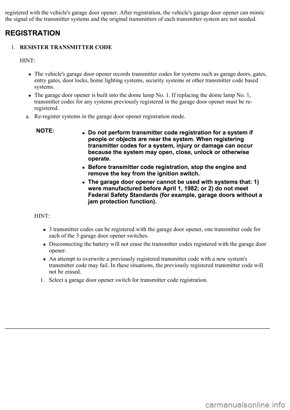
a. Re-register systems in the garage door opener registration mode.
HINT:
3 transmitter codes can be registered with the garage door opener, one transmitter code for
each of the 3 garage door opener switches.
Disconnecting the battery will not erase the transmitter codes registered with the garage door
opener.
An attempt to overwrite a previously registered transmitter code with a new system's
transmitter code may fail. In these situations, the previously registered transmitter code will
not be erased.
1. Select a
garage door opener switch for transmitter code registration.
Page 4185 of 4500
Fig. 2: Selecting Garage Door Opener Switch For Transmitter Code Registration
Courtesy of TOYOTA MOTOR SALES, U.S.A., INC.
2. Press and hold the selected switch for 20 seconds. The garage door opener will enter
registration mode.
HINT:
Before entering registration mode, the LED is ON. After entering registration mode, the LED
flashes at a cycle of 1 Hz. For a "rolling code" type system, after entering registration mode,
the LED flashes at a cycle of 8.8 Hz for 1.6 seconds, and then the LED flashes at a cycle of 1
Hz.
3. After the garage door opener has entered registration mode, bring the original transmitter of
the system to be registered within 1 to 3 inches of the garage door opener and press and hold
one of the
garage door opener switches. Then press the original transmitter switch.
Page 4186 of 4500
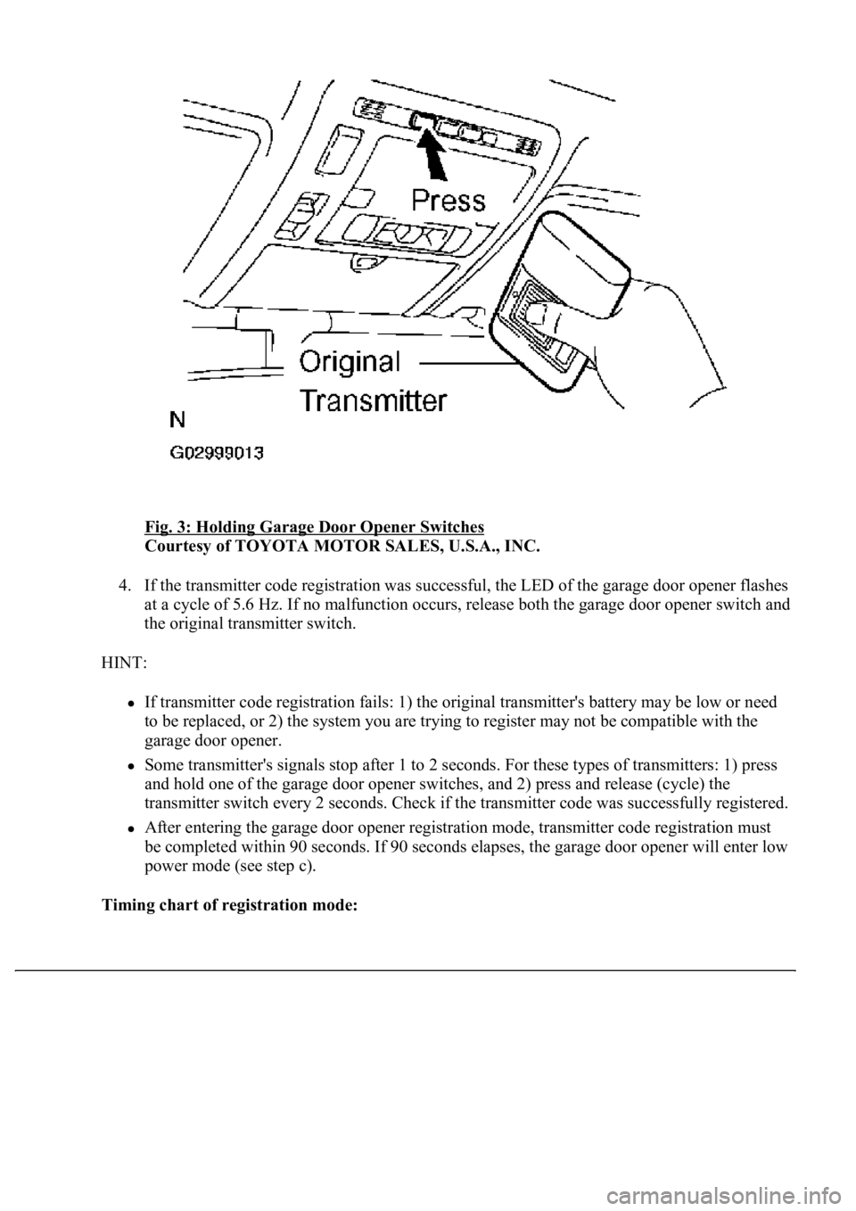
Fig. 3: Holding Garage Door Opener Switches
Courtesy of TOYOTA MOTOR SALES, U.S.A., INC.
4. If the transmitter code registration was successful, the LED of the garage door opener flashes
at a cycle of 5.6 Hz. If no malfunction occurs, release both the garage door opener switch and
the original transmitter switch.
HINT:
If transmitter code registration fails: 1) the original transmitter's battery may be low or need
to be replaced, or 2) the system you are trying to register may not be compatible with the
garage door opener.
Some transmitter's signals stop after 1 to 2 seconds. For these types of transmitters: 1) press
and hold one of the garage door opener switches, and 2) press and release (cycle) the
transmitter switch every 2 seconds. Check if the transmitter code was successfully registered.
After entering the garage door opener registration mode, transmitter code registration must
be completed within 90 seconds. If 90 seconds elapses, the garage door opener will enter low
power mode (see step c).
Timing chart of registration mode: