Page 4188 of 4500

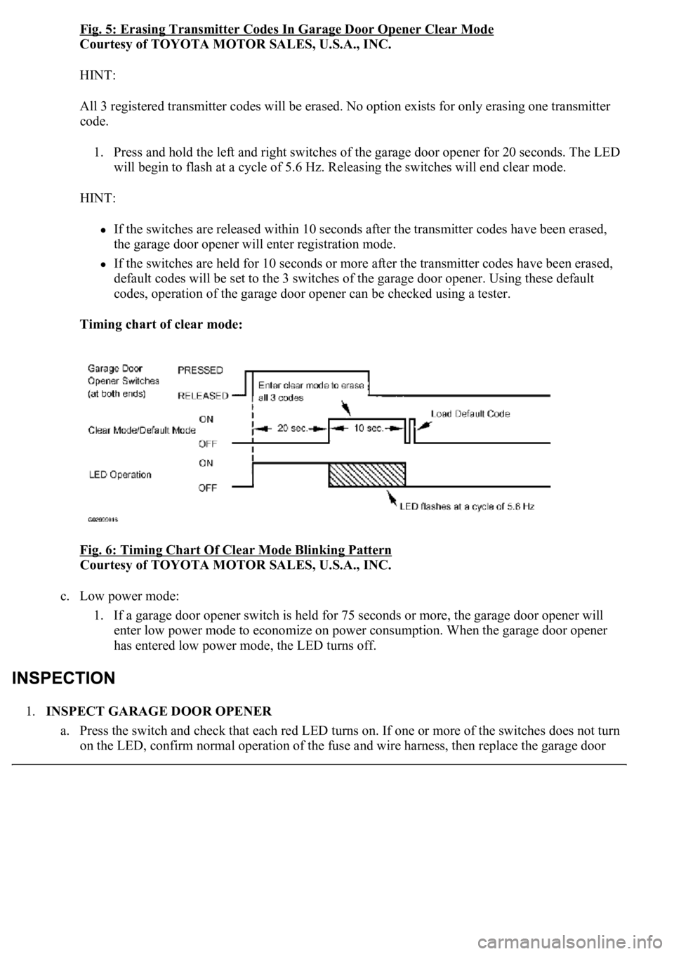
Fig. 5: Erasing Transmitter Codes In Garage Door Opener Clear Mode
Courtesy of TOYOTA MOTOR SALES, U.S.A., INC.
HINT:
All 3 registered transmitter codes will be erased. No option exists for only erasing one transmitter
code.
1. Press and hold the left and right switches of the garage door opener for 20 seconds. The LED
will begin to flash at a cycle of 5.6 Hz. Releasing the switches will end clear mode.
HINT:
If the switches are released within 10 seconds after the transmitter codes have been erased,
the garage door opener will enter registration mode.
If the switches are held for 10 seconds or more after the transmitter codes have been erased,
default codes will be set to the 3 switches of the garage door opener. Using these default
codes, operation of the garage door opener can be checked using a tester.
Timing chart of clear mode:
Fig. 6: Timing Chart Of Clear Mode Blinking Pattern
Courtesy of TOYOTA MOTOR SALES, U.S.A., INC.
c. Low power mode:
1. If a garage door opener switch is held for 75 seconds or more, the garage door opener will
enter low power mode to economize on power consumption. When the garage door opener
has entered low power mode, the LED turns off.
1.INSPECT GARAGE DOOR OPENER
a. Press the switch and check that each red LED turns on. If one or more of the switches does not turn
on the LED, confirm normal operation of the fuse and wire harness, then replace the
garage door
Page 4464 of 4500
Fig. 24: Identifying Vehicle Signal Chart
Courtesy of TOYOTA MOTOR SALES, U.S.A., INC.
4.When the "Vehicle Signal Check Mode" screen is displayed, check all the vehicle signal conditions.
HINT:
Only conditions having inputs are displayed.
This screen is updated once per second when input signals to the vehicle are changed.
HINT:
This mode displays GPS satellite information.
Illustrations may differ from the actual vehicle depending on the device settings and options. Therefore,
some detailed areas may not be shown exactly the same as on the actual vehicle.
1.Enter diagnostic mode (see DIAGNOSTIC START
-UP/FINISH ).
Page 4467 of 4500
Fig. 27: Identifying GPS Information Chart
Courtesy of TOYOTA MOTOR SALES, U.S.A., INC.
4.When GPS information is displayed, check the GPS conditions.
HINT:
This screen is updated once per second when input signals to the vehicle are changed.
HINT:
This mode checks the vehicle signal status to the navigation ECU.
Illustrations may differ from the actual vehicle depending on the device settings and options. Therefore,
some detailed areas may not be shown exactly the same as on the actual vehicle.
1.Enter diagnostic mode (see DIAGNOSTIC START
-UP/FINISH ).
Page 4470 of 4500
Fig. 30: Displaying Vehicle Sensors
Courtesy of TOYOTA MOTOR SALES, U.S.A., INC.
4.Check all the signals and sensors when vehicle signal information is displayed.
HINT:
This screen is updated once per second when input signals to the vehicle are changed.
HINT:
<0037004b004c00560003005000520047004800030046004b00480046004e005600030057004b0048000300460052004f0052005500030047004c00560053004f0044005c00030052005100030057004b00480003005100440059004c004a00440057004c00
5200510003002800260038001100030003[
Illustrations may differ from the actual vehicle depending on the device settings and options. Therefore,
some detailed areas may not be shown exactly the same as on the actual vehicle.
1.Enter diagnostic mode (see DIAGNOSTIC START
-UP/FINISH ).
Page 4483 of 4500
Fig. 43: Displaying Mode Screen
Courtesy of TOYOTA MOTOR SALES, U.S.A., INC.
Screen Description
DISPLAY CONTENTS CHART
d. LAN Monitor (Original) Screen
DisplayContents
Device name/*1Target Device
Segment/*2Target Device Logical address
DTC/*3DTC (Diagnostic Trouble Code)
Timestamp/*4The time and date of past DTCs displayed. (The year is displayed in 2 digit
format.)
Present
Code/*5The DTC output at the service check is displayed.
Past Code/*6Diagnostic memory results and recorded DTCs are displayed.
Page 4485 of 4500
Fig. 46: Displaying LAN Monitor (Individual) Screen
Courtesy of TOYOTA MOTOR SALES, U.S.A., INC.
Screen Description
DISPLAY CONTENTS CHART
2.DISPLAY CHECK
a. Vehicle Signal Check Mode Screen
DisplayContents
Device name/*1Target device
Segment/*2Target logical address
DTC/*3DTC (Diagnostic Trouble Code)
Sub-Code (device
address)/*4Physical address stored with DTC. (If there is no address, nothing is
displayed.)
Connection check No./*5Connection check number stored with DTC.
DTC occurrence/*6Number of times the same DTC has been recorded.
Page 4486 of 4500
Fig. 47: Displaying Vehicle Signal Check Mode Screen
Courtesy of TOYOTA MOTOR SALES, U.S.A., INC.
Screen Description
NAME CONTENTS
HINT:
Only items sending a vehicle signal will be displayed.
This screen is updated once per second when input signals to the vehicle are changed.
3.NAVIGATION CHECK
a. Navigation Check MENU Screen
NameContents
BatteryBattery voltage is displayed.
PKBParking brake ON/OFF state is displayed.
REVReverse signal ON/OFF state is displayed.
IGIG switch ON/OFF state is displayed.
ADIM/TCANBrightness state DIM (with)/ BRIGHT (without) is displayed.
SPEEDThe vehicle speed, displayed in km/h.
TAILTAIL signal (Head lamp dimmer switch) ON/OFF state is displayed.