Page 3254 of 4500

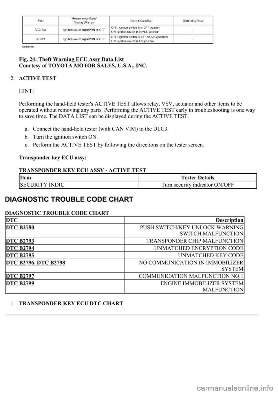
Fig. 24: Theft Warning ECU Assy Data List
Courtesy of TOYOTA MOTOR SALES, U.S.A., INC.
2.ACTIVE TEST
HINT:
Performing the hand-held tester's ACTIVE TEST allows relay, VSV, actuator and other items to be
operated without removing any parts. Performing the ACTIVE TEST early in troubleshooting is one way
to save time. The DATA LIST can be displayed during the ACTIVE TEST.
a. Connect the hand-held tester (with CAN VIM) to the DLC3.
b. Turn the ignition switch ON.
c. Perform the ACTIVE TEST by following the directions on the tester screen.
Transponder key ECU assy:
TRANSPONDER KEY ECU ASSY - ACTIVE TEST
DIAGNOSTIC TROUBLE CODE CHART
1.TRANSPONDER KEY ECU DTC CHART
ItemTester Details
SECURITY INDICTurn security indicator ON/OFF
DTCDescription
DTC B2780PUSH SWITCH/KEY UNLOCK WARNING
SWITCH MALFUNCTION
DTC B2793TRANSPONDER CHIP MALFUNCTION
DTC B2794UNMATCHED ENCRYPTION CODE
DTC B2795UNMATCHED KEY CODE
DTC B2796, DTC B2798NO COMMUNICATION IN IMMOBILIZER
SYSTEM
DTC B2797COMMUNICATION MALFUNCTION NO.1
DTC B2799ENGINE IMMOBILIZER SYSTEM
MALFUNCTION
Page 3255 of 4500
Fig. 25: Transponder Key ECU DTC Chart
Courtesy of TOYOTA MOTOR SALES, U.S.A., INC.
2.ECM DTC CHART
Fig. 26: ECM DTC Chart
Courtesy of TOYOTA MOTOR SALES, U.S.A., INC.
CIRCUIT DESCRIPTION
This DTC will be output if the transponder key ECU does not detect that the unlock warning switch is ON even
when the ignition switch is ON. Under the normal conditions, the unlock warning switch is ON when the
i
gnition switch is ON.
Page 3256 of 4500
Fig. 27: DTC Reference Chart
Courtesy of TOYOTA MOTOR SALES, U.S.A., INC.
WIRING DIAGRAM
Fig. 28: DTC B2780
- Wiring Diagram
Courtesy of TOYOTA MOTOR SALES, U.S.A., INC.
INSPECTION PROCEDURE
1.READ DATA LIST USING HAND-HELD TESTER
a. Connect the hand-held tester to the CAN VIM. Then connect the CAN VIM to the DLC3.
b. Turn the ignition switch ON with the key that cannot start the engine.
c. Read the DATA LIST.
Transponder key ECU assy:
Page 3257 of 4500
Fig. 29: Transponder Key ECU Assy Data List
Courtesy of TOYOTA MOTOR SALES, U.S.A., INC.
OK: "ON" (Key is in ignition key cylinder) appears on the screen.
NG: Go to step 2
OK: REPLACE TRANSPONDER KEY ECU ASSY
2.INSPECT UNLOCK WARNING SWITCH ASSY
a. Remove the unlock warning switch.
b. Measure the resistance of the switch.
Fig. 30: Inspecting Unlock Warning Switch Assy
Page 3260 of 4500
4.CHECK WIRE HARNESS (TRANSPONDER KEY ECU ASSY - UNLOCK WARNING SWITCH
ASSY)
a. Disconnect the T9 ECU connector.
b. Disconnect the U7 switch connector.
c. Measure the resistance of the wire harness side connectors.
Page 3262 of 4500

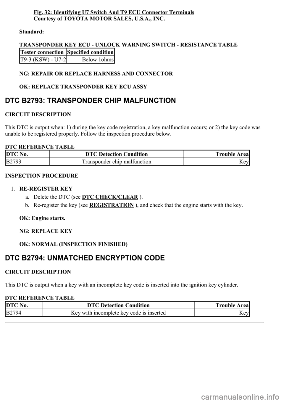
Fig. 32: Identifying U7 Switch And T9 ECU Connector Terminals
Courtesy of TOYOTA MOTOR SALES, U.S.A., INC.
Standard:
TRANSPONDER KEY ECU - UNLOCK WARNING SWITCH - RESISTANCE TABLE
NG: REPAIR OR REPLACE HARNESS AND CONNECTOR
OK: REPLACE TRANSPONDER KEY ECU ASSY
CIRCUIT DESCRIPTION
This DTC is output when: 1) during the key code registration, a key malfunction occurs; or 2) the key code was
unable to be registered properly. Follow the inspection procedure below.
DTC REFERENCE TABLE
INSPECTION PROCEDURE
1.RE-REGISTER KEY
a. Delete the DTC (see DTC CHECK/CLEAR
).
b. Re-register the key (see REGISTRATION
), and check that the engine starts with the key.
OK: Engine starts.
NG: REPLACE KEY
OK: NORMAL (INSPECTION FINISHED)
CIRCUIT DESCRIPTION
This DTC is output when a key with an incomplete key code is inserted into the ignition key cylinder.
DTC REFERENCE TABLE
Tester connectionSpecified condition
T9-3 (KSW) - U7-2Below 1ohms
DTC No.DTC Detection ConditionTrouble Area
B2793Transponder chip malfunctionKey
DTC No.DTC Detection ConditionTrouble Area
B2794Key with incomplete key code is insertedKey
Page 3263 of 4500
INSPECTION PROCEDURE
REPLACE KEY
CIRCUIT DESCRIPTION
This DTC is output when a key with a key code that has not been registered in the ECU is inserted into the
ignition key cylinder.
DTC REFERENCE TABLE
INSPECTION PROCEDURE
1.DELETE DTC AND INSERT ALL PRESENTLY AVAILABLE KEYS TO CHECK WHETHER
ENGINE STARTS OR NOT
OK: Engine starts.
NG: REPLACE KEY THAT CANNOT START ENGINE
OK: NO PROBLEM (BECAUSE OF KEY RE-REGISTRATION)
CIRCUIT DESCRIPTION
This DTC is output when a key that does not have a transponder chip is inserted into the ignition key cylinder or
if communication between the key and transponder key ECU is not possible.
Fig. 33: DTC Reference Chart
Courtesy of TOYOTA MOTOR SALES, U.S.A., INC.
WIRING DIAGRAM
DTC No.DTC Detection ConditionTrouble Area
B2795Key with unregistered key code is insertedKey
Page 3264 of 4500
Fig. 34: DTCs B2796, B2798 - Wiring Diagram
Courtesy of TOYOTA MOTOR SALES, U.S.A., INC.
INSPECTION PROCEDURE
1.READ DATA LIST USING HAND-HELD TESTER
a. Connect the hand-held tester to the CAN VIM. Then connect the CAN VIM to the DLC3.
b. Turn the ignition switch ON with the key that cannot start the engine.
c. Read the DATA LIST.
Transponder key ECU assy:
Fig. 35: Transponder Key ECU Assy Data List
Courtesy of TOYOTA MOTOR SALES, U.S.A., INC.
OK: "UNSET" (Ignition switch ON) appears on the screen.
NG: Go to step 2
OK: REPLACE TRANSPONDER KEY ECU ASSY
2.CHECK WHETHER ENGINE STARTS WITH OTHER KEYS