Page 3489 of 4500
Fig. 206: Taping Damper Using SST And Hammer
Courtesy of TOYOTA MOTOR SALES, U.S.A., INC.
b. Using SST, install the damper bolt.
SST 09213-7001 1, 09330-00021
Torque: 245 N.m (2,500 kgf.cm, 181 ft.lbf)
c. Ali
gn the pulley set key with the key groove of the crankshaft damper.
Page 3587 of 4500
Fig. 303: Taping In Oil Seal Using SST And A Hammer
Courtesy of TOYOTA MOTOR SALES, U.S.A., INC.
5.INSTALL CRANKSHAFT TIMING PULLEY
a. Align the timing pulley set key with the key groove of the pulley.
b. Face the timing pulley's flange side inward. Using SST and a hammer, tap in the timing pulley.
SST 09223-4601 1
Page 3588 of 4500
Fig. 304: Aligning Timing Pulley Setting Key With Key Groove
Courtesy of TOYOTA MOTOR SALES, U.S.A., INC.
6.INSTALL TIMING BELT (See REPLACEMENT
)
REPLACEMENT
1.REMOVE AUTOMATIC TRANSMISSION ASSY (See REPLACEMENT
)
2.REMOVE DRIVE PLATE & RING GEAR SUB-ASSY
a. Using SST, hold the crankshaft damper.
SST 09213-7001 1, 09330-00021
Page 3871 of 4500
REPLACEMENT
HINT:
The installation procedures are the removal procedures in reverse order.
A bolt without torque specification is a standard bolt (see SPECIFIED TORQUE FOR STANDARD
BOLTS ).
1.REMOVE REAR COMBINATION LAMP SERVICE COVER RH (See OVERHAUL
)
2.REMOVE REAR COMBINATION LAMP SERVICE COVER LH (See OVERHAUL
)
3.REMOVE LUGGAGE COMPARTMENT LAMP ASSY NO. (See step 4 in OVERHAUL
)
4.REMOVE BACK DOOR TRIM COVER (See step 5 in OVERHAUL
)
5.REMOVE LUGGAGE COMPARTMENT DOOR GARNISH SUB-ASSY OUTSIDE
a. Remove the 6 nuts and key cylinder. Then remove the luggage compartment door opener switch.
b.Disengage the 4 clips and remove the garnish from the luggage compartment door.
Page 3965 of 4500

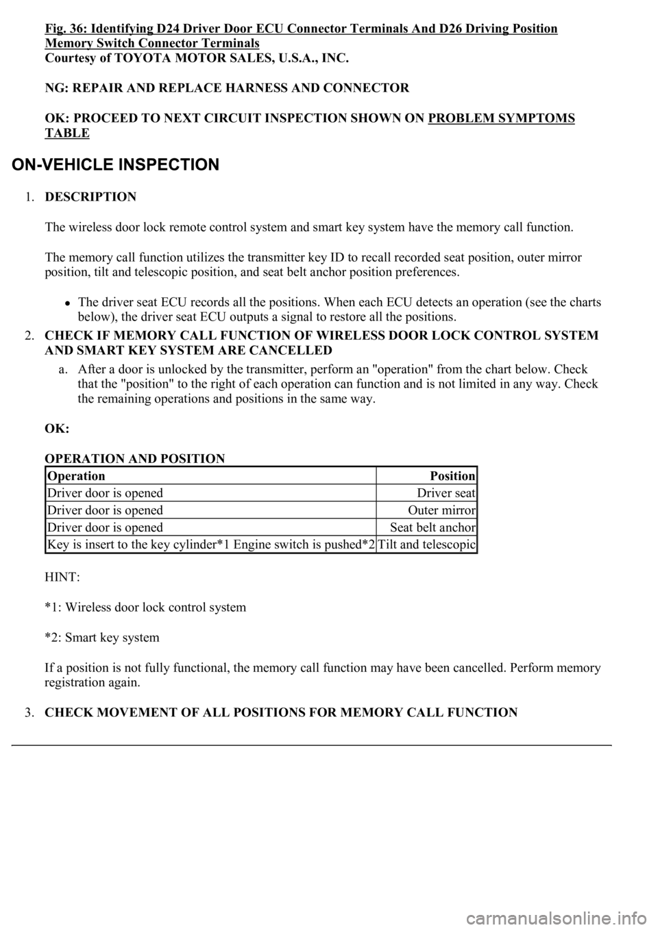
Fig. 36: Identifying D24 Driver Door ECU Connector Terminals And D26 Driving Position
Memory Switch Connector Terminals
Courtesy of TOYOTA MOTOR SALES, U.S.A., INC.
NG: REPAIR AND REPLACE HARNESS AND CONNECTOR
OK: PROCEED TO NEXT CIRCUIT INSPECTION SHOWN ON PROBLEM SYMPTOMS
TABLE
1.DESCRIPTION
The wireless door lock remote control system and smart key system have the memory call function.
The memory call function utilizes the transmitter key ID to recall recorded seat position, outer mirror
position, tilt and telescopic position, and seat belt anchor position preferences.
The driver seat ECU records all the positions. When each ECU detects an operation (see the charts
below), the driver seat ECU outputs a signal to restore all the positions.
2.CHECK IF MEMORY CALL FUNCTION OF WIRELESS DOOR LOCK CONTROL SYSTEM
AND SMART KEY SYSTEM ARE CANCELLED
a. After a door is unlocked by the transmitter, perform an "operation" from the chart below. Check
that the "position" to the right of each operation can function and is not limited in any way. Check
<0057004b004800030055004800500044004c0051004c0051004a0003005200530048005500440057004c00520051005600030044005100470003005300520056004c0057004c0052005100560003004c005100030057004b00480003005600440050004800
03005a0044005c001100030003[
OK:
OPERATION AND POSITION
HINT:
*1: Wireless door lock control system
*2: Smart key system
If a position is not fully functional, the memory call function may have been cancelled. Perform memory
registration again.
3.CHECK MOVEMENT OF ALL POSITIONS FOR MEMORY CALL FUNCTION
OperationPosition
Driver door is openedDriver seat
Driver door is openedOuter mirror
Driver door is openedSeat belt anchor
<002e0048005c0003004c00560003004c0051005600480055005700030057005200030057004b00480003004e0048005c00030046005c004f004c0051004700480055000d0014000300280051004a004c0051004800030056005a004c00570046004b000300
4c00560003005300580056004b00480047000d0015[Tilt and telescopic
Page 3967 of 4500
OPERATION AND TILT AND TELESCOPIC POSITION OPERATION
HINT:
*1: Wireless door lock control system
*2: Smart key system
If the result is not as specified, inspect the tilt and telescopic.
4.CHECK FRONT POWER SEAT FUNCTION
a. Check the basic functions.
1. Operate the power seat switches and check to make sure each seat function works:
Sliding
Front vertical
Lifter
Reclining
Lumbar support
Cushion sliding
Headrest
OperationTilt and Telescopic Position Operation
Key is inserted to the key cylinder*1 Engine switch is
pushed*2Vertical tilt position
Key is inserted to the key cylinder*1 Engine switch is
pushed*2Telescopic flexibility (lengthening and
shortening)
Page 3971 of 4500

signaling that the seat position has been recorded.
3. Change the position of the seat and then press the M2 switch. Check that the buzzer sounds
for 0.1 seconds and the seat automatically moves to the position in step (c)-(1).
d. Check the M3 switch.
1. Using the seat switches, fully slide the seat rearward, fully recline the seatback rearward and
fully lower the seat cushion and headrest.
2. Press and hold down switches M3 and SET. Check that the buzzer sounds for 0.5 seconds,
signaling that the seat position has been recorded.
3. Change the position of the seat and then press the M3 switch. Check that the buzzer sounds
for 0.1 seconds and the seat automatically moves to the position in step (d)-(1).
e. Check that the switches M1, M2 and M3 cause the seat to move to the recorded seat positions
under these conditions: turn the ignition switch to the LOCK position, remove the key from the key
cylinder, open the driver side door and press M1, M2 or M3 within 30 seconds.
f. Check that the following procedures will erase the recorded seat positions of switches M1, M2 and
M3: press and hold the power seat slide switch, disconnect the battery's negative terminal cable,
and wait for at least 1 minute.
g. Restore the seat's memory.
1. Using the seat switches, fully slide the seat forward, fully recline the seatback forward, and
fully raise the seat cushion and headrest.
2. Using the seat switches, fully slide the seat rearward, fully recline the seatback rearward and
fully lower the seat cushion and headrest.
HINT:
This will restore the seat's memory of the seat's maximum positions. However, it will not restore
any recorded seat positions to switches M1, M2 or M3.
h. Attempt to record a seat position by pressing and holding the SET switch and two other switches
<000b0044005000520051004a000300300014000f0003003000150003004400510047000300300016000c0011000300310052000300560048004400570003005300520056004c0057004c0052005100030056004b00520058004f0047000300450048000300
550048004600520055004700480047001100030026004b0048[ck this by pressing M1, M2 or
M3 and making sure that the seat does not move.
HINT:
This step will only be true if step (f) was performed properly, whereby all previously recorded set
positions were erased.
1.Passenger's seat:
INSPECT POWER SEAT SWITCH
a. Measure the resistance between the terminals when each switch is operated.
Standard:
Page 4162 of 4500
Fig. 2: Identifying Engine Room No. 1 Junction & Relay Block Components
Courtesy of TOYOTA MOTOR SALES, U.S.A., INC.
Engine Room No. 1 Junction & Relay Block Fuses
FuseSystem
7.5AA/C IGAutomatic Air Conditioning (Front)
7.5AEFI NO.2Engine Control
7.5AFR IGABS
Automatic Air Conditioning (Front)
Back-Up Light
Charging
Clock (w/ LEXUS Navigation System)
Cruise Control
Door Closer (w/ Smart Key System)
Door Closer (w/o Smart Key System)
Door Lock Control (w/ Smart Key System)
Door Lock Control (w/o Smart Key System)