Page 407 of 4500
Fig. 152: Checking Harness And Connector (Air Conditioning Amplifier - Body Ground)
Courtesy of TOYOTA MOTOR SALES, U.S.A., INC.
OK: REPLACE AIR CONDITIONING AMPLIFIER (SEE REPLACEMENT
)
CIRCUIT DESCRIPTION
This is the power source for the A/C amplifier and servomotors, etc.
WIRING DIAGRAM
Page 413 of 4500

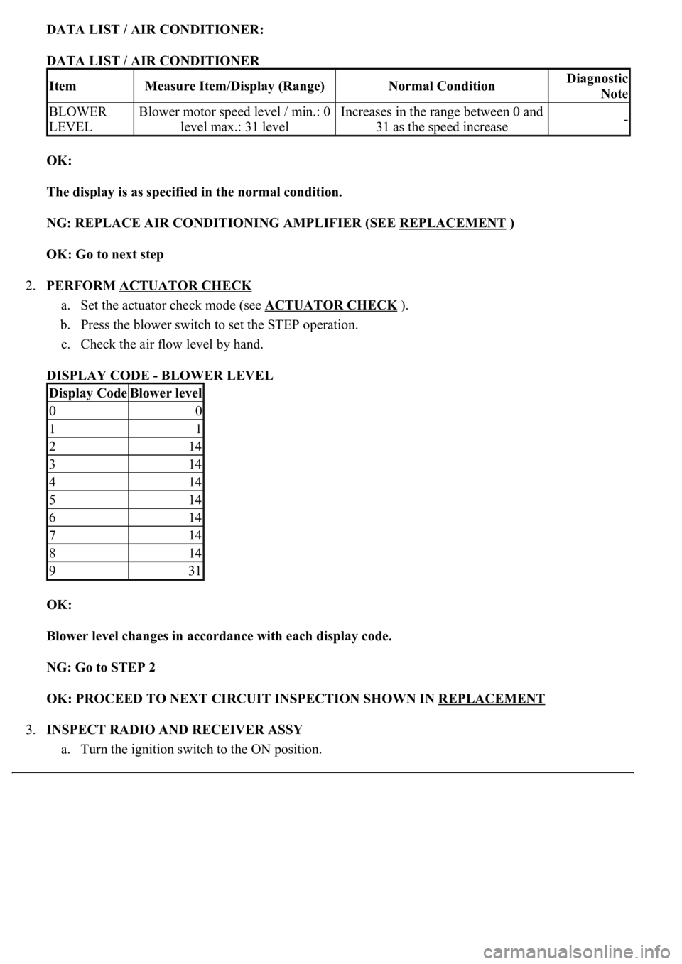
DATA LIST / AIR CONDITIONER:
DATA LIST / AIR CONDITIONER
OK:
The display is as specified in the normal condition.
NG: REPLACE AIR CONDITIONING AMPLIFIER (SEE REPLACEMENT
)
OK: Go to next step
2.PERFORM ACTUATOR CHECK
a. Set the actuator check mode (see ACTUATOR CHECK
).
b. Press the blower switch to set the STEP operation.
c. Check the air flow level by hand.
DISPLAY CODE - BLOWER LEVEL
OK:
<0025004f0052005a004800550003004f004800590048004f00030046004b00440051004a004800560003004c0051000300440046004600520055004700440051004600480003005a004c0057004b0003004800440046004b00030047004c00560053004f00
44005c000300460052004700480011[
NG: Go to STEP 2
OK: PROCEED TO NEXT CIRCUIT INSPECTION SHOWN IN REPLACEMENT
3.INSPECT RADIO AND RECEIVER ASSY
a. Turn the ignition switch to the ON position.
ItemMeasure Item/Display (Range)Normal ConditionDiagnostic
Note
BLOWER
LEVELBlower motor speed level / min.: 0
level max.: 31 levelIncreases in the range between 0 and
31 as the speed increase-
Display CodeBlower level
00
11
214
314
414
514
614
714
814
931
Page 420 of 4500
c. Turn the blower switch on (Lo).
<0029004c004a00110003001400190016001d0003002c005100560053004800460057004c0051004a00030024004c005500030026005200510047004c0057004c00520051004c0051004a0003002400500053004f004c0049004c004800550003000b002500
2f003a0003[
- Body Ground)
Courtesy of TOYOTA MOTOR SALES, U.S.A., INC.
d. Measure the waveform between terminal BLW (A11-5) of the A/C amplifier and body ground.
OK:
Waveform operate as shown in the illustration.
HINT:
Waveform varies with the blower level.
NG: REPLACE AIR CONDITIONING AMPLIFIER (SEE REPLACEMENT
)
Page 467 of 4500
Courtesy of TOYOTA MOTOR SALES, U.S.A., INC.
OK: REPLACE AIR CONDITIONING AMPLIFIER (SEE REPLACEMENT
)
Page 500 of 4500
NG: Go to step 3
OK: REPLACE SUSPENSION CONTROL ECU (SEE REPLACEMENT
)
3.CHECK HARNESS AND CONNECTOR (HEIGHT CONTROL SENSOR SUB-ASSY POWER
SOURCE) (SEE ELECTRONIC CIRCUIT INSPECTION PROCEDURE
)
a. Disconnect the height control sensor sub-assy connector.
b. Turn the ignition switch to the ON position.
c. Measure the voltage according to the value (s) in the table below.
TESTER CONNECTION STANDARD SPECIFIED CONDITION (FRONT RH)
Fig. 22: Identifying Front Height Control Sensor Sub
-Assy Connector Terminals
Courtesy of TOYOTA MOTOR SALES, U.S.A., INC.
TESTER CONNECTION STANDARD SPECIFIED CONDITION Standard (Front LH)
Tester ConnectionSpecified Condition
H14-1 (SHB) - H14-4 (SHG)4.5 to 5.5 V
Tester ConnectionSpecified Condition
H13-1 (SHB) - H13-4 (SHG)4.5 to 5.5 V
Page 511 of 4500
Fig. 33: Identifying Height Control Sensor Rear LH Connector Terminals
Courtesy of TOYOTA MOTOR SALES, U.S.A., INC.
B: REPLACE HEIGHT CONTROL SENSOR SUB-ASSY FRONT RH (SEE REPLACEMENT
)
C: REPLACE HEIGHT CONTROL SENSOR SUB-ASSY FRONT LH (SEE REPLACEMENT
)
D: REPLACE HEIGHT CONTROL SENSOR SUB-ASSY REAR RH (SEE REPLACEMENT
)
E: REPLACE HEIGHT CONTROL SENSOR SUB-ASSY REAR LH (SEE REPLACEMENT
)
A: REPLACE SUSPENSION CONTROL ECU (SEE REPLACEMENT
)
4.CHECK HARNESS AND CONNECTOR (SUSPENSION CONTROL ECU - HEIGHT
CONTROL SENSOR SUB-ASSY) (SEE ELECTRONIC CIRCUIT INSPECTION PROCEDURE
)
a. Disconnect the suspension control ECU A20 or A22 connector.
b. Measure the resistance according to the value (s) in the table below.
Page 524 of 4500
Fig. 46: Identifying Height Control Sensor Rear LH Connector Terminals
Courtesy of TOYOTA MOTOR SALES, U.S.A., INC.
B: REPLACE HEIGHT CONTROL SENSOR SUB-ASSY FRONT RH (SEE REPLACEMENT
)
C: REPLACE HEIGHT CONTROL SENSOR SUB-ASSY FRONT LH (SEE REPLACEMENT
)
D: REPLACE HEIGHT CONTROL SENSOR SUB-ASSY REAR RH (SEE REPLACEMENT
)
E: REPLACE HEIGHT CONTROL SENSOR SUB-ASSY REAR LH (SEE REPLACEMENT
)
A: REPLACE SUSPENSION CONTROL ECU (SEE REPLACEMENT
)
Page 527 of 4500
Acceleration value must change.
RESULT DESCRIPTION
B: Go to step 2
C: Go to step 3
D: REPLACE LEFT FRONT ACCELERATION SENSOR
HINT:
For the left front acceleration sensor failure, replace the suspension control ECU.
A: REPLACE SUSPENSION CONTROL ECU (SEE REPLACEMENT
)
2.INSPECT HEIGHT CONTROL SENSOR SUB-ASSY FRONT RH
a. Remove the height control sensor sub-assy front RH.
b. Connect 3 dry batteries of 1.5 V in series.
c. Connect terminal 1 (SHB) to the batteries' positive (+) terminal, and terminal 4 (SHG) to the
batteries' negative (-) terminal, then apply voltage of approximately 4.5 V between terminals 4
(SHG) and 3 (SGFR) for the following conditions.
SENSOR CONDITION AND VOLTAGE SPECIFICATIONS
OKA
NG (right front acceleration sensor)B
NG (rear acceleration sensor)C
NG (left front acceleration sensor)D
Sensor conditionVoltage
Sensor stationaryApprox. 2.3 V
Sensor vibrating verticallyChange between approx. 1.0 to 4.0 V