Page 4168 of 4500
Fig. 5: Identifying Driver Side Junction Block Components (Fuses)
Courtesy of TOYOTA MOTOR SALES, U.S.A., INC.
Page 4169 of 4500
Fig. 6: Identifying Driver Side Junction Block Components (Relays)
Courtesy of TOYOTA MOTOR SALES, U.S.A., INC.
Driver Side Junction Block Fuses
FuseSystem
Page 4173 of 4500
PASSENGER SIDE JUNCTION BLOCK
Fig. 7: Identifying Passenger Side Junction Block Components (Fuses)
Courtesy of TOYOTA MOTOR SALES, U.S.A., INC.
15AD S/HTRClimate Control Seat (Front)
Seat Heater (Front)
15AD-CIGCigarette Lighter and Power Outlet
15APWR OUTLETCigarette Lighter and Power Outlet
20AAIRBUSElectronic Modulated Air Suspension
20ATI&TEPower Tilt and Power Telescopic
30AD P/SEATPower Seat (Driver's Seat)
Page 4174 of 4500
Fig. 8: Identifying Passenger Side Junction Block Components (Relays)
Courtesy of TOYOTA MOTOR SALES, U.S.A., INC.
Passenger Side Junction Block Fuses
Page 4175 of 4500

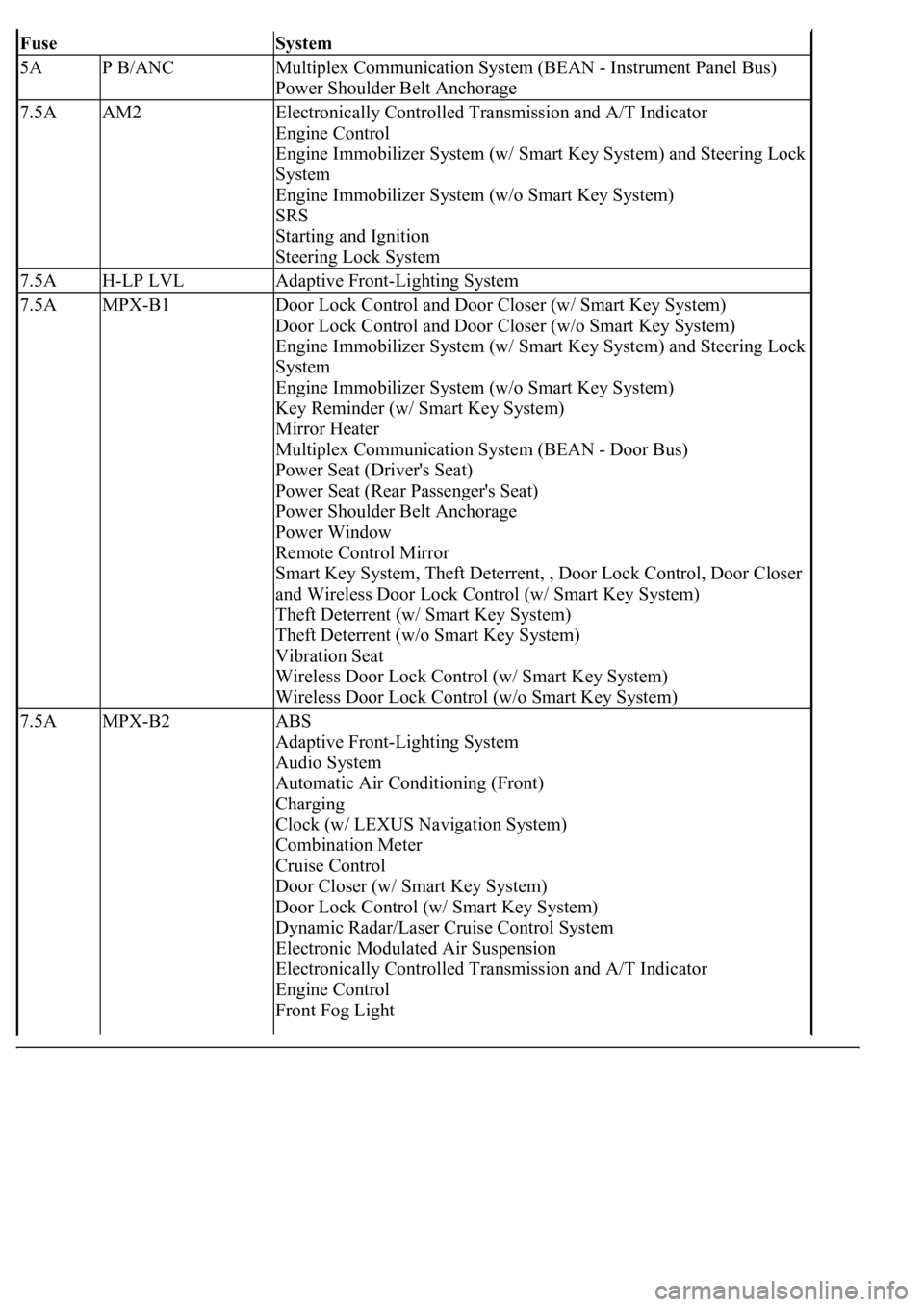
FuseSystem
5AP B/ANCMultiplex Communication System (BEAN - Instrument Panel Bus)
Power Shoulder Belt Anchorage
7.5AAM2Electronically Controlled Transmission and A/T Indicator
Engine Control
Engine Immobilizer System (w/ Smart Key System) and Steering Lock
System
Engine Immobilizer System (w/o Smart Key System)
SRS
Starting and Ignition
Steering Lock System
7.5AH-LP LVLAdaptive Front-Lighting System
7.5AMPX-B1Door Lock Control and Door Closer (w/ Smart Key System)
Door Lock Control and Door Closer (w/o Smart Key System)
Engine Immobilizer System (w/ Smart Key System) and Steering Lock
System
Engine Immobilizer System (w/o Smart Key System)
Key Reminder (w/ Smart Key System)
Mirror Heater
Multiplex Communication System (BEAN - Door Bus)
Power Seat (Driver's Seat)
Power Seat (Rear Passenger's Seat)
Power Shoulder Belt Anchorage
Power Window
Remote Control Mirror
Smart Key System, Theft Deterrent, , Door Lock Control, Door Closer
and Wireless Door Lock Control (w/ Smart Key System)
Theft Deterrent (w/ Smart Key System)
Theft Deterrent (w/o Smart Key System)
Vibration Seat
Wireless Door Lock Control (w/ Smart Key System)
Wireless Door Lock Control (w/o Smart Key System)
7.5AMPX-B2ABS
Adaptive Front-Lighting System
Audio System
Automatic Air Conditioning (Front)
Charging
Clock (w/ LEXUS Navigation System)
Combination Meter
Cruise Control
Door Closer (w/ Smart Key System)
Door Lock Control (w/ Smart Key System)
Dynamic Radar/Laser Cruise Control System
Electronic Modulated Air Suspension
Electronically Controlled Transmission and A/T Indicator
Engine Control
Front Fog Light
Page 4181 of 4500
Fig. 10: Identifying Luggage Room Junction Block Components
Courtesy of TOYOTA MOTOR SALES, U.S.A., INC.
Luggage Room Junction Block
FuseSystem
7.5ALCE LPLight Auto Turn Off System
Page 4188 of 4500

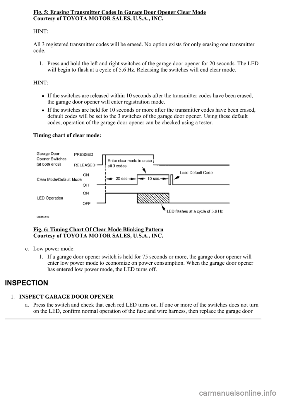
Fig. 5: Erasing Transmitter Codes In Garage Door Opener Clear Mode
Courtesy of TOYOTA MOTOR SALES, U.S.A., INC.
HINT:
All 3 registered transmitter codes will be erased. No option exists for only erasing one transmitter
code.
1. Press and hold the left and right switches of the garage door opener for 20 seconds. The LED
will begin to flash at a cycle of 5.6 Hz. Releasing the switches will end clear mode.
HINT:
If the switches are released within 10 seconds after the transmitter codes have been erased,
the garage door opener will enter registration mode.
If the switches are held for 10 seconds or more after the transmitter codes have been erased,
default codes will be set to the 3 switches of the garage door opener. Using these default
codes, operation of the garage door opener can be checked using a tester.
Timing chart of clear mode:
Fig. 6: Timing Chart Of Clear Mode Blinking Pattern
Courtesy of TOYOTA MOTOR SALES, U.S.A., INC.
c. Low power mode:
1. If a garage door opener switch is held for 75 seconds or more, the garage door opener will
enter low power mode to economize on power consumption. When the garage door opener
has entered low power mode, the LED turns off.
1.INSPECT GARAGE DOOR OPENER
a. Press the switch and check that each red LED turns on. If one or more of the switches does not turn
on the LED, confirm normal operation of the fuse and wire harness, then replace the
garage door
Page 4322 of 4500
SYSTEM DIAGRAM
Fig. 2: Identifying Horn System Diagram
Courtesy of TOYOTA MOTOR SALES, U.S.A., INC.
PROBLEM SYMPTOMS TABLE
Fig. 3: Problem Symptoms Table
Courtesy of TOYOTA MOTOR SALES, U.S.A., INC.
INSPECTION
1.INSPECT FUSE (HORN)