Page 3932 of 4500
INSPECTION PROCEDURE
1.INSPECT FUSE (D/C CUT, D P/SEAT, MPX-IG, AM1, MPX-B1)
a. Remove the D/C CUT fuse from the FL block.
b. Remove the D P/SEAT, MPX-IG and AM1 fuses from the driver side J/B.
c. Remove the MPX-B1 fuse from the passenger side J/B.
d. Measure the resistance of the fuse.
Standard: Below 1 ohms
NG: REPLACE FUSE
OK: GO TO NEXT STEP
2.INSPECT RELAY (Marking: D-IG1)
a. Remove the D-IG1 relay from the driver side J/B.
b. Measure the resistance of the relay.
Standard:
TESTER CONNECTION AND SPECIFIED CONDITION
Tester connectionSpecified condition
3 - 510 kohms or higher
3 - 5Below 1 ohms (when battery voltage is applied to terminals 1 and 2)
Page 3935 of 4500
Fig. 18: Power Source Circuit (Driver Door ECU) - Wiring Diagram
Courtesy of TOYOTA MOTOR SALES, U.S.A., INC.
INSPECTION PROCEDURE
1.INSPECT FUSE (MPX-B1, AM1, MPX-IG, D DOOR)
a. Remove the MPX-IG and AM1 fuses from the driver side J/B.
b. Remove the D DOOR and MPX-B1 fuses from the passenger side J/B.
c. Measure the resistance of the fuse.
Standard: Below 1 ohms
Page 3936 of 4500
NG: REPLACE FUSE
OK: GO TO NEXT STEP
2.INSPECT RELAY (D-IG1)
a. Remove the D-IG1 relay from the driver side J/B.
b. Measure the resistance of the relay.
Standard:
TESTER CONNECTION AND SPECIFIED CONDITION
Fig. 19: Identifying D
-IG1 Relay Terminals
Courtesy of TOYOTA MOTOR SALES, U.S.A., INC.
NG: REPLACE RELAY
OK: GO TO NEXT STEP
3.CHECK WIRE HARNESS (DRIVER DOOR ECU - BATTERY AND BODY GROUND)
Tester connectionSpecified condition
3 - 510 kohms or higher
3 - 5Below 1 ohms (when battery voltage is applied to terminals 1 and 2)
Page 4085 of 4500
INSPECTION PROCEDURE
1.INSPECT FUSE (MPX-B3, MPX-IG and AM1, D/C CUT)
a. Remove the MPX-B3 fuse from the passenger side J/B.
b. Remove the MPX-IG and AM1 fuse from the driver side J/B.
c. Remove the D/C CUT fuse from the FL block assy.
d. Measure the resistance.
Standard: Below 1 ohms
NG: REPLACE FUSE
OK: GO TO NEXT STEP
2.CHECK WIRE HARNESS (LUGGAGE ROOM J/B ECU - BATTERY AND BODY GROUND)
a. Disconnect the LA, LF and LL J/B, and L14 ECU connectors.
b. Measure the resistance and voltage of the wire harness side connectors.
Standard:
TESTER CONNECTION AND SPECIFIED CONDITION
Tester connectionConditionSpecified condition
LF-13 (MPX-IG) - Body groundIgnition switch ON10 to 14 V
LF-12 (MPX-B) - Body groundAlways10 to 14 V
LL-1 (L-O/C (P)) - Body groundAlways10 to 14 V
LA-5 (P-GND) - Body groundAlwaysBelow 1 ohms
L14-5 (SG) - Body groundAlwaysBelow 1 ohms
Page 4093 of 4500
OK: Fuel lid opener is opened.
NG: Go to step 2
OK: PROCEED TO NEXT CIRCUIT INSPECTION SHOWN ON PROBLEM SYMPTOMS
TABLE
2.INSPECT FUSE (FUEL OPN)
a. Remove the FUEL OPN fuse from the luggage room J/B.
b. Measure the resistance.
Standard: Below 1 ohms
NG: REPLACE FUSE
OK: GO TO NEXT STEP
3.INSPECT FUEL LID OPENER MOTOR ASSY
a. Apply battery voltage to the motor and check operation of the fuel lid opener motor.
OK:
MEASUREMENT CONDITION
NG: REPLACE FUEL LID OPENER MOTOR ASSY
ItemTest DetailDiagnostic Note
FUEL LID OPENOperate fuel lid motor OFF/ON-
Measurement ConditionSpecified Condition
Battery positive (+) --> Terminal 2 Battery negative (-) --> Terminal 1Moves to open direction
Page 4113 of 4500
Fig. 15: Connecting Hand-Held Tester DLC3
Courtesy of TOYOTA MOTOR SALES, U.S.A., INC.
c. Select the ACTIVE TEST mode on the hand-held tester.
d. Please refer to the hand-held tester operator's manual for further details.
e. Check that there is pressure in the fuel inlet hose from the fuel filter.
HINT:
If there is fuel pressure, you will hear the sound of fuel flowing. If there is no pressure, check the
fusible link, fuses, EFI MAIN relay, fuel pump, ECM and wiring connections.
f. Turn the ignition switch to LOCK.
g. Disconnect the hand-held tester from the DLC3.
2.CHECK FUEL PRESSURE
a. Check that the battery positive voltage is above 12 V.
b. Disconnect the negative (-) terminal cable from the battery.
c. Remove the fuel pressure pulsation damper from the RH delivery pipe (see REPLACEMENT
).
d. Install the fuel pipe sub-ass
y No. 2 and SST (pressure gauge) to the delivery pipe with the 3 lower
Page 4162 of 4500
Fig. 2: Identifying Engine Room No. 1 Junction & Relay Block Components
Courtesy of TOYOTA MOTOR SALES, U.S.A., INC.
Engine Room No. 1 Junction & Relay Block Fuses
FuseSystem
7.5AA/C IGAutomatic Air Conditioning (Front)
7.5AEFI NO.2Engine Control
7.5AFR IGABS
Automatic Air Conditioning (Front)
Back-Up Light
Charging
Clock (w/ LEXUS Navigation System)
Cruise Control
Door Closer (w/ Smart Key System)
Door Closer (w/o Smart Key System)
Door Lock Control (w/ Smart Key System)
Door Lock Control (w/o Smart Key System)
Page 4166 of 4500

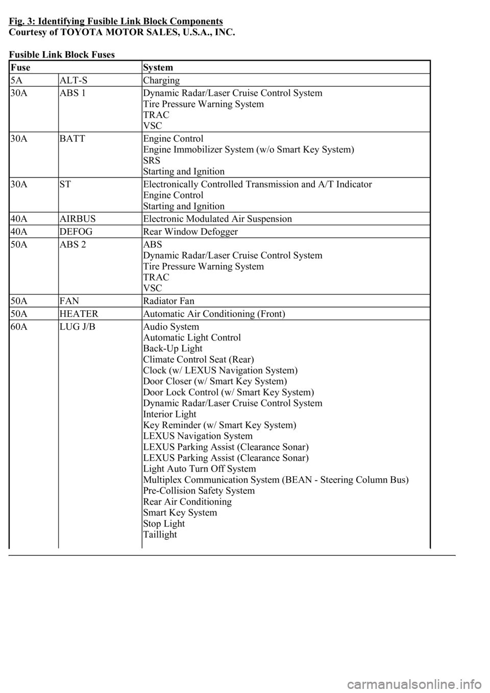
Fig. 3: Identifying Fusible Link Block Components
Courtesy of TOYOTA MOTOR SALES, U.S.A., INC.
Fusible Link Block Fuses
FuseSystem
5AALT-SCharging
30AABS 1Dynamic Radar/Laser Cruise Control System
Tire Pressure Warning System
TRAC
VSC
30ABATTEngine Control
Engine Immobilizer System (w/o Smart Key System)
SRS
Starting and Ignition
30ASTElectronically Controlled Transmission and A/T Indicator
Engine Control
Starting and Ignition
40AAIRBUSElectronic Modulated Air Suspension
40ADEFOGRear Window Defogger
50AABS 2ABS
Dynamic Radar/Laser Cruise Control System
Tire Pressure Warning System
TRAC
VSC
50AFANRadiator Fan
50AHEATERAutomatic Air Conditioning (Front)
60ALUG J/BAudio System
Automatic Light Control
Back-Up Light
Climate Control Seat (Rear)
Clock (w/ LEXUS Navigation System)
Door Closer (w/ Smart Key System)
Door Lock Control (w/ Smart Key System)
Dynamic Radar/Laser Cruise Control System
Interior Light
Key Reminder (w/ Smart Key System)
LEXUS Navigation System
LEXUS Parking Assist (Clearance Sonar)
LEXUS Parking Assist (Clearance Sonar)
Light Auto Turn Off System
Multiplex Communication System (BEAN - Steering Column Bus)
Pre-Collision Safety System
Rear Air Conditioning
Smart Key System
Stop Light
Taillight