Page 4158 of 4500
45.INSTALL DIFFERENTIAL SUPPORT PROTECTOR NO.2
46.INSTALL DIFFERENTIAL SUPPORT PROTECTOR NO.1
47.INSTALL FRONT FLOOR HEAT INSULATOR NO.1
a. Install the front floor heat insulator with the 4 bolts.
Torque: 5.4 N.m (55 kgf.cm, 47 in..lbf)
48.INSTALL PROPELLER SHAFT HEAT INSULATOR
49.INSTALL EXHAUST PIPE ASSY (See REPLACEMENT
)
50.INSTALL ENGINE UNDER COVER NO.2
51.INSTALL FRONT FLOOR BRACE CENTER (See OVERHAUL
)
52.INSTALL REAR FLOOR SERVICE HOLE COVER
53.INSTALL FUEL TANK MAIN TUBE SUB-ASSY
a. Connect the connector on the fuel tank side.
1. Attach the fuel tube connector to the port of the fuel suction plate.
2. Install the tube joint clip.
b. Connect the connector on the fuel pipe side.
1. Insert the connector by aligning the axes of the pipe and the connector until the retainer makes a
click sound.
Page 4159 of 4500
Fig. 56: Connecting Connector
Courtesy of TOYOTA MOTOR SALES, U.S.A., INC.
54.INSTALL REAR FLOOR SERVICE HOLE COVER NO.2 (See REPLACEMENT
)
55.INSTALL BENCH TYPE REAR SEAT CUSHION ASSY (FIXED TYPE REAR SEAT) (See
OVERHAUL
)
56.INSTALL SEPARATE TYPE REAR SEAT CUSHION ASSY LH (SEPARATED TYPE REAR
SEAT) (See OVERHAUL
)
57.ADD FUEL (See PRECAUTION
)
58.CONNECT BATTERY NEGATIVE TERMINAL
Page 4196 of 4500
overheating etc.
9.DO NOT OPERATE ENGINE AND COMPRESSOR WITH NO REFRIGERANT
10.SUPPLEMENTAL RESTRAINT SYSTEM (SRS)
The LEXUS LS430 is equipped with an SRS (Supplemental Restraint system) such as the driver, front
passenger, side, curtain shield air bags etc.. Failure to carry out service operation in the correct sequence
could cause the SRS to unexpectedly deploy during servicing, possibly leading to a serious accident.
Before servicing (including removal or installation of parts, inspection or replacement), be sure to read
the precautionary notices in PRECAUTION
.
11.PRECAUTION FOR DISCONNECTING THE BATTERY CABLE
DISCONNECTING BATTERY CABLE
LOCATION
System NameProceed To
Front Power Seat Control SystemINITIALIZATION
Page 4267 of 4500
Fig. 80: Removing W/Pulley Compressor Assy
Courtesy of TOYOTA MOTOR SALES, U.S.A., INC.
10.ADJUST COMPRESSOR OIL
a. When replacing the compressor and magnetic clutch with a new one, after gradually removing the
refrigerant gas from the service valve, drain the following amount of oil from the new compressor
and magnetic clutch before installation.
Standard:
(Oil capacity inside the new compressor: 130 +15 cc (4.4 +0.5 fl.oz)) - (Remaining oil
amount in the removed compressor) = (Oil amount to be removed from the new
compressor when replacing)
Page 4351 of 4500

PRECAUTION
1. HANDLING PRECAUTIONS FOR STEERING SYSTEM
a. Care must be taken when replacing parts. Incorrect replacement could affect the performance of the
steering system and result in a driving hazard.
2. HANDLING PRECAUTIONS FOR SRS AIRBAG SYSTEM
a. The LS430 is equipped with SRS (Supplemental Restraint System) such as the driver airbag and
front passenger airbag, etc. Failure to carry out service operations in the correct sequence could
cause the SRS to unexpectedly deploy during servicing, possibly leading to a serious accident.
Before servicing (including removal or installation of parts, inspection or replacement), be sure to
read the precautionary notice for the supplemental restraint system (see PRECAUTION
).
REPLACEMENT
HINT:
COMPONENTS: SEE COMPONENTS
Installation is in the reverse order of removal.
A bolt without a torque specification is shown in the standard bolt chart (see STANDARD BOLT ).
1. TABLE OF BOLT, SCREW AND NUT
HINT:
The bolts, screws and nuts, necessary for installation and removal of the instrument panel, are shown in
the illustration below with alphabet code.
Page 4425 of 4500

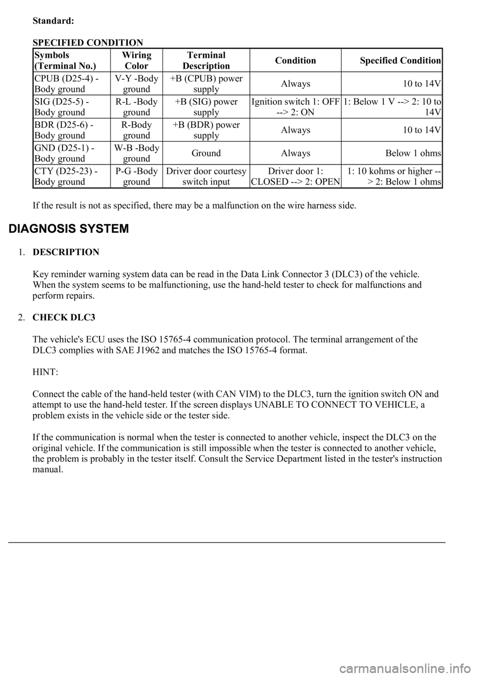
Standard:
SPECIFIED CONDITION
If the result is not as specified, there may be a malfunction on the wire harness side.
1.DESCRIPTION
Key reminder warning system data can be read in the Data Link Connector 3 (DLC3) of the vehicle.
When the system seems to be malfunctioning, use the hand-held tester to check for malfunctions and
perform repairs.
2.CHECK DLC3
The vehicle's ECU uses the ISO 15765-4 communication protocol. The terminal arrangement of the
DLC3 complies with SAE J1962 and matches the ISO 15765-4 format.
HINT:
Connect the cable of the hand-held tester (with CAN VIM) to the DLC3, turn the ignition switch ON and
attempt to use the hand-held tester. If the screen displays UNABLE TO CONNECT TO VEHICLE, a
problem exists in the vehicle side or the tester side.
If the communication is normal when the tester is connected to another vehicle, inspect the DLC3 on the
original vehicle. If the communication is still impossible when the tester is connected to another vehicle,
the problem is probably in the tester itself. Consult the Service Department listed in the tester's instruction
manual.
Symbols
(Terminal No.)Wiring
ColorTerminal
DescriptionConditionSpecified Condition
CPUB (D25-4) -
Body groundV-Y -Body
ground+B (CPUB) power
supplyAlways10 to 14V
SIG (D25-5) -
Body groundR-L -Body
ground+B (SIG) power
supplyIgnition switch 1: OFF
--> 2: ON1: Below 1 V --> 2: 10 to
14V
BDR (D25-6) -
Body groundR-Body
ground+B (BDR) power
supplyAlways10 to 14V
GND (D25-1) -
Body groundW-B -Body
groundGroundAlwaysBelow 1 ohms
CTY (D25-23) -
Body groundP-G -Body
groundDriver door courtesy
switch inputDriver door 1:
CLOSED --> 2: OPEN1: 10 kohms or higher --
> 2: Below 1 ohms
Page 4483 of 4500
Fig. 43: Displaying Mode Screen
Courtesy of TOYOTA MOTOR SALES, U.S.A., INC.
Screen Description
DISPLAY CONTENTS CHART
d. LAN Monitor (Original) Screen
DisplayContents
Device name/*1Target Device
Segment/*2Target Device Logical address
DTC/*3DTC (Diagnostic Trouble Code)
Timestamp/*4The time and date of past DTCs displayed. (The year is displayed in 2 digit
format.)
Present
Code/*5The DTC output at the service check is displayed.
Past Code/*6Diagnostic memory results and recorded DTCs are displayed.