Page 4103 of 4500

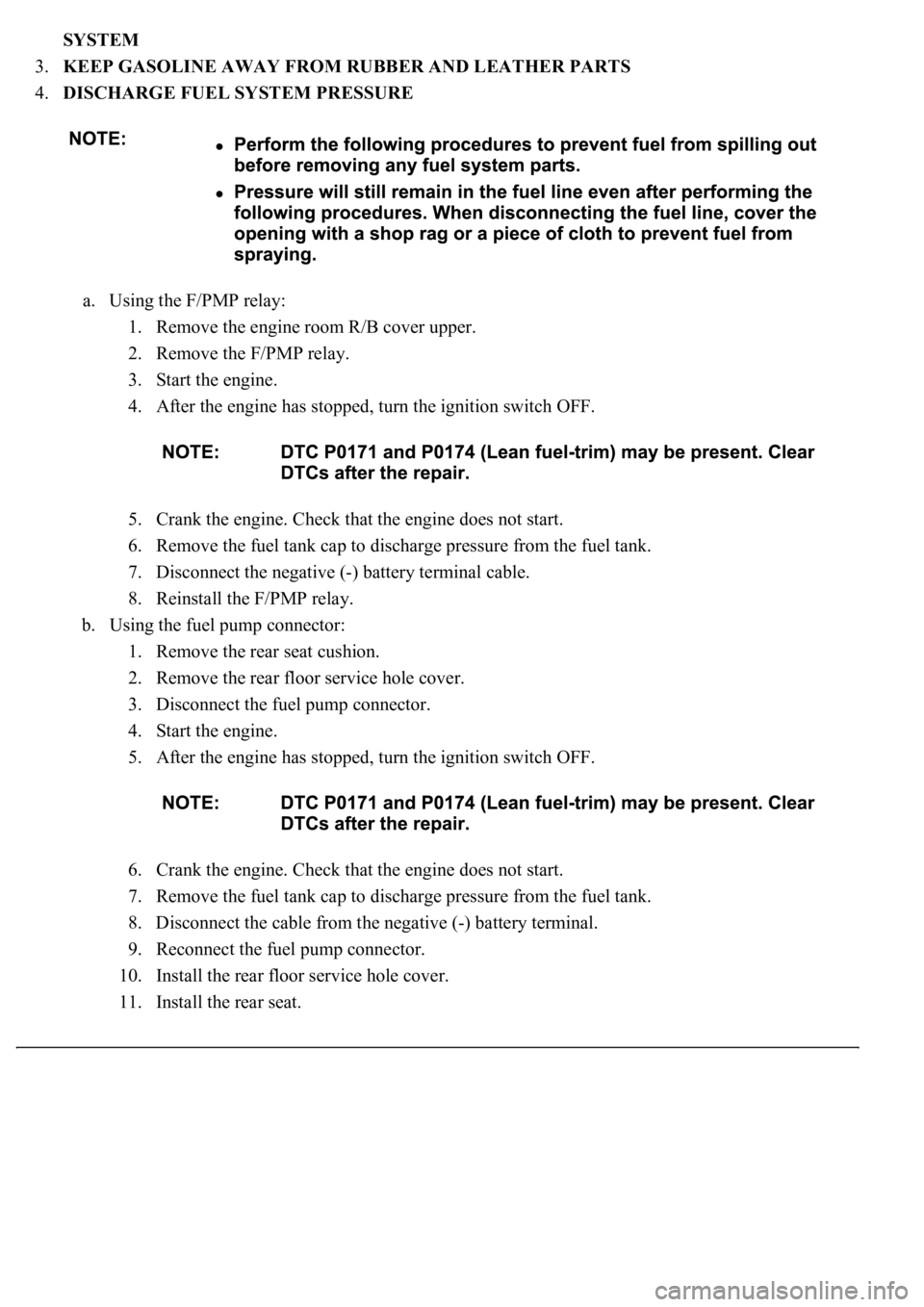
SYSTEM
3.KEEP GASOLINE AWAY FROM RUBBER AND LEATHER PARTS
4.DISCHARGE FUEL SYSTEM PRESSURE
a. Using the F/PMP relay:
1. Remove the engine room R/B cover upper.
2. Remove the F/PMP relay.
3. Start the engine.
4. After the engine has stopped, turn the ignition switch OFF.
5. Crank the engine. Check that the engine does not start.
6. Remove the fuel tank cap to discharge pressure from the fuel tank.
7. Disconnect the negative (-) battery terminal cable.
8. Reinstall the F/PMP relay.
b. Using the fuel pump connector:
1. Remove the rear seat cushion.
2. Remove the rear floor service hole cover.
3. Disconnect the fuel pump connector.
4. Start the engine.
5. After the engine has stopped, turn the ignition switch OFF.
6. Crank the engine. Check that the engine does not start.
7. Remove the fuel tank cap to discharge pressure from the fuel tank.
8. Disconnect the cable from the negative (-) battery terminal.
9. Reconnect the fuel pump connector.
10. Install the rear floor service hole cover.
11. Install the rear seat.
Page 4116 of 4500
<0029004c004a001100030014001a001d0003003000480044005600580055004c0051004a0003003500480056004c0056005700440051004600480003002500480057005a00480048005100030037004800550050004c00510044004f005600030017000300
240051004700030018[
Courtesy of TOYOTA MOTOR SALES, U.S.A., INC.
a. Remove the rear seat cushion.
b. Remove the 3 cap nuts and floor service hole cover.
c. Disconnect the fuel pump & sender gauge connector.
d. Using an ohmmeter, measure the resistance between terminals 4 and 5.
Standard: 0.2 to 3.0 ohms at 20°C (68°F)
If the resistance is not as specified, replace the fuel pump.
e. Inspect the fuel pump operation.
Connect the battery's positive (+) lead to terminal 4 of the connector, and the negative (-) lead to
terminal 5. Check that the fuel pump operates.
Page 4117 of 4500
Fig. 18: Inspecting Fuel Pump Operation
Courtesy of TOYOTA MOTOR SALES, U.S.A., INC.
<002c00490003005200530048005500440057004c005200510003004c0056000300510052005700030044005600030056005300480046004c0049004c00480047000f0003005500480053004f00440046004800030057004b00480003004900580048004f00
03005300580050005300110003[
f. Reconnect the fuel pump & sender gauge connector.
g. Reinstall the floor service hole cover with the cap nuts.
h. Reinstall the rear seat cushion.
INSPECTION
1.INSPECT FUEL INJECTOR ASSY
a. Inspect the in
jector resistance.
Page 4137 of 4500
REPLACEMENT
1.WORK FOR PREVENTING GASOLINE FROM SPILLING OUT (See PRECAUTION
)
2.DISCONNECT BATTERY NEGATIVE TERMINAL
3.DRAIN FUEL (See PRECAUTION
)
4.REMOVE SEPARATE TYPE REAR SEAT CUSHION ASSY LH (SEPARATED TYPE REAR
SEAT) (See OVERHAUL
)
5.REMOVE BENCH TYPE REAR SEAT CUSHION ASSY (FIXED TYPE REAR SEAT) (See
OVERHAUL
)
6.REMOVE REAR FLOOR SERVICE HOLE COVER NO.2
a. Remove the 3 cap nuts and service hole cover.
7.REMOVE FUEL TANK MAIN TUBE SUB-ASSY
Page 4148 of 4500
Fig. 47: Installing Fuel Tube Connector
Courtesy of TOYOTA MOTOR SALES, U.S.A., INC.
25.INSTALL REAR FLOOR SERVICE HOLE COVER NO.2
Install the service hole cover with the 3 cap nuts.
Page 4149 of 4500
Fig. 48: Installing Service Hole Cover
Courtesy of TOYOTA MOTOR SALES, U.S.A., INC.
26.INSTALL BENCH TYPE REAR SEAT CUSHION ASSY (FIXED TYPE REAR SEAT) (See
OVERHAUL
)
27.INSTALL SEPARATE TYPE REAR SEAT CUSHION ASSY LH (SEPARATED TYPE REAR
SEAT) (See OVERHAUL
)
28.ADD FUEL (See PRECAUTION
)
29.CONNECT BATTERY NEGATIVE TERMINAL
30.INSPECT FUEL PUMP OPERATION AND CHECK FOR FUEL LEAKS (See ON
-VEHICLE
INSPECTION )
COMPONENTS
Page 4151 of 4500
1.WORK FOR PREVENTING GASOLINE FROM SPILLING OUT (See PRECAUTION )
2.DISCONNECT BATTERY NEGATIVE TERMINAL
3.DRAIN FUEL (See PRECAUTION
)
4.REMOVE SEPARATE TYPE REAR SEAT CUSHION ASSY LH (SEPARATED TYPE REAR
SEAT) (See OVERHAUL
)
5.REMOVE BENCH TYPE REAR SEAT CUSHION ASSY (FIXED TYPE REAR SEAT) (See
OVERHAUL
)
6.REMOVE REAR FLOOR SERVICE HOLE COVER NO.2 (See REPLACEMENT
)
7.REMOVE FUEL TANK MAIN TUBE SUB-ASSY
a. Disconnect the connector in the fuel tank side.
1. Remove the tube joint clip.
2. Pull out the fuel main tube.
3. Plu
g the port of the fuel suction plate with a clean rubber cap.
Page 4153 of 4500
Fig. 51: Pulling Out Connector
Courtesy of TOYOTA MOTOR SALES, U.S.A., INC.
c. Protect each connecting part from damage and contamination by covering it with a vinyl bag.
8.REMOVE REAR FLOOR SERVICE HOLE COVER
a. Remove the service hole cover and disconnect the fuel sender gauge connector.
9.REMOVE FRONT FLOOR BRACE CENTER (See OVERHAUL
)
10.REMOVE ENGINE UNDER COVER NO.2
11.REMOVE EXHAUST PIPE ASSY (See REPLACEMENT
)
12.REMOVE PROPELLER SHAFT HEAT INSULATOR
13.REMOVE FRONT FLOOR HEAT INSULATOR NO.1
a. Remove the 2 bolts and propeller shaft heat insulator.
14.REMOVE DIFFERENTIAL SUPPORT PROTECTOR NO.1
15.REMOVE DIFFERENTIAL SUPPORT PROTECTOR NO.2
16.REMOVE PROPELLER SHAFT ASSY (See OVERHAUL
)
17.REMOVE PARKING BRAKE CABLE ASSY NO.2 (See REPLACEMENT
)
18.REMOVE PARKING BRAKE CABLE ASSY NO.3 (See REPLACEMENT
)
19.REMOVE FUEL TANK TO FILLER PIPE HOSE
20.REMOVE FUEL TANK EVAPORATION VENT TUBE
21.REMOVE FUEL TANK BREATHER HOSE