Page 3529 of 4500
<0029004c004a00110003001500170018001d00030036004800570057004c0051004a00030037004c0050004c0051004a0003003000440055004e00030032004900030026004400500056004b004400490057000300300044004c00510003002a0048004400
55[
Courtesy of TOYOTA MOTOR SALES, U.S.A., INC.
a. Bring the service bolt hole of the sub gear upward by turning the hexagon wrench head portion of
the exhaust camshaft with a wrench.
b. Secure the sub gear to the main gear with a service bolt.
RECOMMENDED SERVICE BOLT:
RECOMMENDED SERVICE BOLT
HINT:
When removin
g the camshaft, make sure that the torsional spring force of the sub gear has been
Thread diameter6mm
Thread pitch1.0 mm
Bolt length16 to 20 mm (0.63 to 0.79 in.)
Page 3536 of 4500
Fig. 252: Removing Service Bolt Using SST
Courtesy of TOYOTA MOTOR SALES, U.S.A., INC.
Using SST, turn the sub gear clockwise and remove the service bolt.
SST 09960-10010 (09962-01000, 09963-00500)
Page 3542 of 4500
Fig. 258: Inserting Oil Seal Into Camshaft Timing Tube
Courtesy of TOYOTA MOTOR SALES, U.S.A., INC.
d. Using SST, align the holes of the driven main gear and sub gear by turning the sub gear clockwise,
and temporarily install a service bolt.
SST 09960-10010 (09962-01000, 09963-00500)
e. Ali
gn the gear teeth of the driven main gear and sub gear, and tighten the service bolt.
Page 3553 of 4500
Fig. 269: Removing Service Bolt
Courtesy of TOYOTA MOTOR SALES, U.S.A., INC.
k. Install 4 new seal washers to the bearing cap bolts (1 to 4).
l. Apply a light coat of engine oil on the threads and under the heads of the bearing cap bolts (5 to
22).
m. Install the oil feed pipe and the 22 bearing cap bolts.
n. Uniformly tighten the 22 bearing cap bolts in several passes in the sequence shown in the
illustration.
Torque:
<001a0011001800030031001100500003000b001a001a0003004e004a0049001100460050000f0003001900190003004c005100110011004f00450049000c0003004900520055000300450052004f00570003000b0015001400030044005100470003001500
15000c[
16 N.m (163 kgf.cm, 12 ft.lbf) for others
Page 3554 of 4500
Fig. 270: Installing Camshaft Timing Pulley Sub-Assy LH
Courtesy of TOYOTA MOTOR SALES, U.S.A., INC.
o. Remove the service bolt.
12.INSTALL CAMSHAFT TIMING OIL CONTROL VALVE ASSY
Page 3871 of 4500
REPLACEMENT
HINT:
The installation procedures are the removal procedures in reverse order.
A bolt without torque specification is a standard bolt (see SPECIFIED TORQUE FOR STANDARD
BOLTS ).
1.REMOVE REAR COMBINATION LAMP SERVICE COVER RH (See OVERHAUL
)
2.REMOVE REAR COMBINATION LAMP SERVICE COVER LH (See OVERHAUL
)
3.REMOVE LUGGAGE COMPARTMENT LAMP ASSY NO. (See step 4 in OVERHAUL
)
4.REMOVE BACK DOOR TRIM COVER (See step 5 in OVERHAUL
)
5.REMOVE LUGGAGE COMPARTMENT DOOR GARNISH SUB-ASSY OUTSIDE
a. Remove the 6 nuts and key cylinder. Then remove the luggage compartment door opener switch.
b.Disengage the 4 clips and remove the garnish from the luggage compartment door.
Page 3925 of 4500

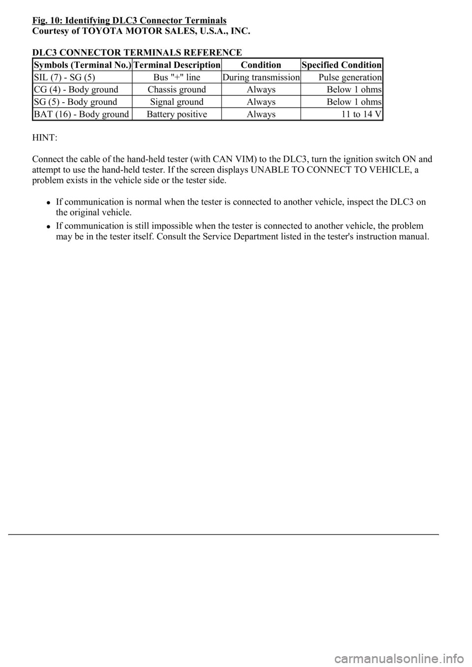
Fig. 10: Identifying DLC3 Connector Terminals
Courtesy of TOYOTA MOTOR SALES, U.S.A., INC.
DLC3 CONNECTOR TERMINALS REFERENCE
HINT:
Connect the cable of the hand-held tester (with CAN VIM) to the DLC3, turn the ignition switch ON and
attempt to use the hand-held tester. If the screen displays UNABLE TO CONNECT TO VEHICLE, a
problem exists in the vehicle side or the tester side.
If communication is normal when the tester is connected to another vehicle, inspect the DLC3 on
the original vehicle.
If communication is still impossible when the tester is connected to another vehicle, the problem
may be in the tester itself. Consult the Service Department listed in the tester's instruction manual.
Symbols (Terminal No.)Terminal DescriptionConditionSpecified Condition
SIL (7) - SG (5)Bus "+" lineDuring transmissionPulse generation
CG (4) - Body groundChassis groundAlwaysBelow 1 ohms
SG (5) - Body groundSignal groundAlwaysBelow 1 ohms
BAT (16) - Body groundBattery positiveAlways11 to 14 V
Page 4081 of 4500
Fig. 11: Identifying Terminals Of DLC3
Courtesy of TOYOTA MOTOR SALES, U.S.A., INC.
2.CHECK DLC3
The vehicle's ECU uses the ISO 15765-4 communication protocol. The terminal arrangement of the
DLC3 complies with SAE J1962 and matches the ISO 15765-4 format.
HINT:
Connect the cable of the hand-held tester (with CAN VIM) to the DLC3, turn the ignition switch ON and
attempt to use the hand-held tester. If the screen displays UNABLE TO CONNECT TO VEHICLE, a
problem exists in the vehicle side or the tester side.
If the communication is normal when the tester is connected to another vehicle, inspect the DLC3 on the
original vehicle.
If the communication is still impossible when the tester is connected to another vehicle, the problem is
probably in the tester itself. Consult the Service Department listed in the tester's instruction manual.
TERMINAL DESCRIPTION AND SPECIFIED CONDITION