2003 DODGE RAM 5 speed manual transmission
[x] Cancel search: 5 speed manual transmissionPage 1890 of 2895
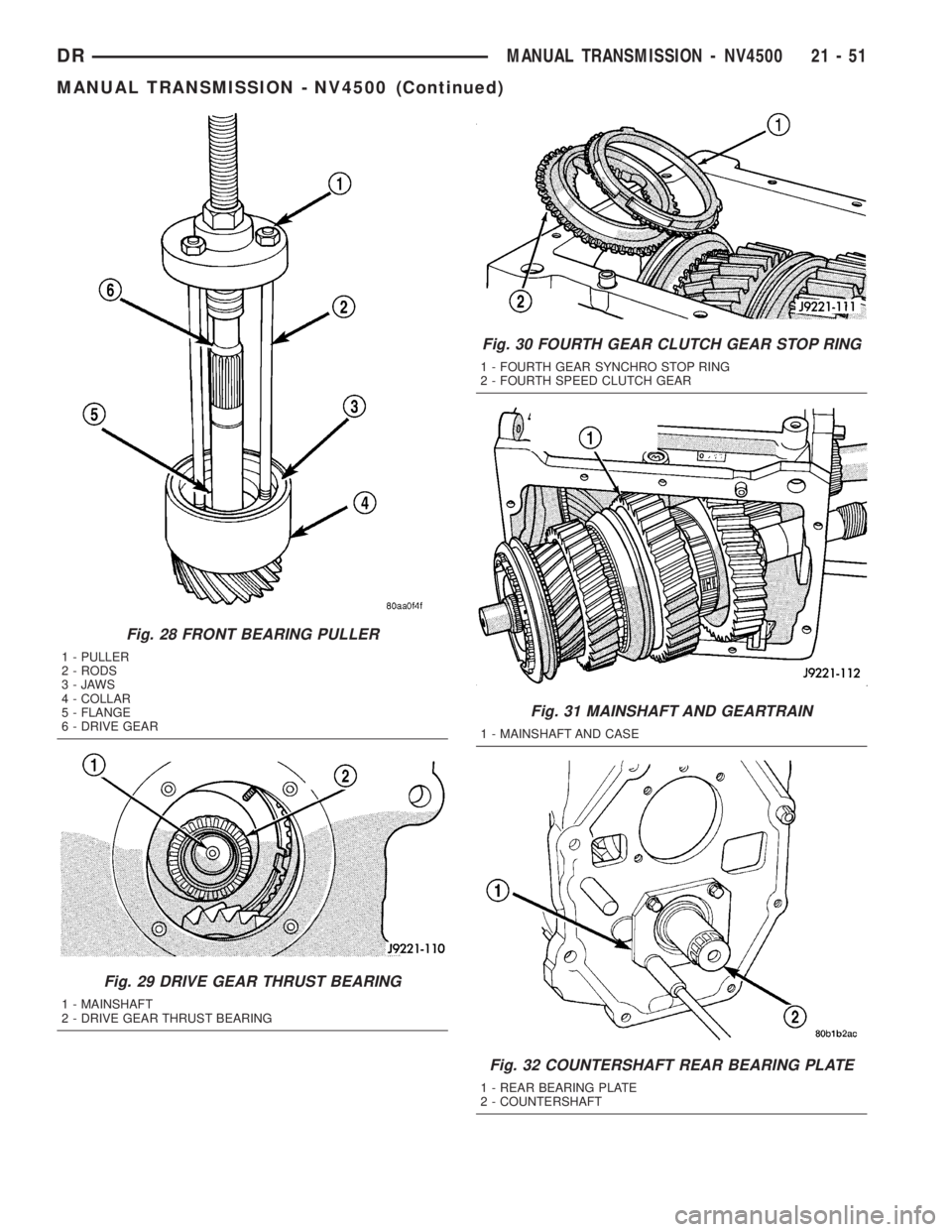
Fig. 28 FRONT BEARING PULLER
1 - PULLER
2 - RODS
3-JAWS
4 - COLLAR
5 - FLANGE
6 - DRIVE GEAR
Fig. 29 DRIVE GEAR THRUST BEARING
1 - MAINSHAFT
2 - DRIVE GEAR THRUST BEARING
Fig. 30 FOURTH GEAR CLUTCH GEAR STOP RING
1 - FOURTH GEAR SYNCHRO STOP RING
2 - FOURTH SPEED CLUTCH GEAR
Fig. 31 MAINSHAFT AND GEARTRAIN
1 - MAINSHAFT AND CASE
Fig. 32 COUNTERSHAFT REAR BEARING PLATE
1 - REAR BEARING PLATE
2 - COUNTERSHAFT
DRMANUAL TRANSMISSION - NV4500 21 - 51
MANUAL TRANSMISSION - NV4500 (Continued)
Page 1896 of 2895
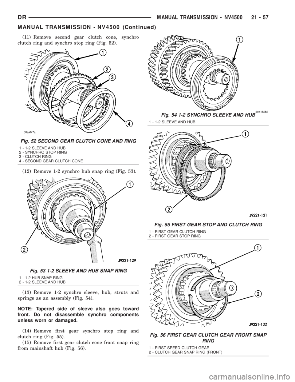
(11) Remove second gear clutch cone, synchro
clutch ring and synchro stop ring (Fig. 52).
(12) Remove 1-2 synchro hub snap ring (Fig. 53).
(13) Remove 1-2 synchro sleeve, hub, struts and
springs as an assembly (Fig. 54).
NOTE: Tapered side of sleeve also goes toward
front. Do not disassemble synchro components
unless worn or damaged.
(14) Remove first gear synchro stop ring and
clutch ring (Fig. 55).
(15) Remove first gear clutch cone front snap ring
from mainshaft hub (Fig. 56).
Fig. 52 SECOND GEAR CLUTCH CONE AND RING
1 - 1-2 SLEEVE AND HUB
2 - SYNCHRO STOP RING
3 - CLUTCH RING
4 - SECOND GEAR CLUTCH CONE
Fig. 53 1-2 SLEEVE AND HUB SNAP RING
1 - 1-2 HUB SNAP RING
2 - 1-2 SLEEVE AND HUB
Fig. 54 1-2 SYNCHRO SLEEVE AND HUB
1 - 1-2 SLEEVE AND HUB
Fig. 55 FIRST GEAR STOP AND CLUTCH RING
1 - FIRST GEAR CLUTCH RING
2 - FIRST GEAR STOP RING
Fig. 56 FIRST GEAR CLUTCH GEAR FRONT SNAP
RING
1 - FIRST SPEED CLUTCH GEAR
2 - CLUTCH GEAR SNAP RING (FRONT)
DRMANUAL TRANSMISSION - NV4500 21 - 57
MANUAL TRANSMISSION - NV4500 (Continued)
Page 1897 of 2895
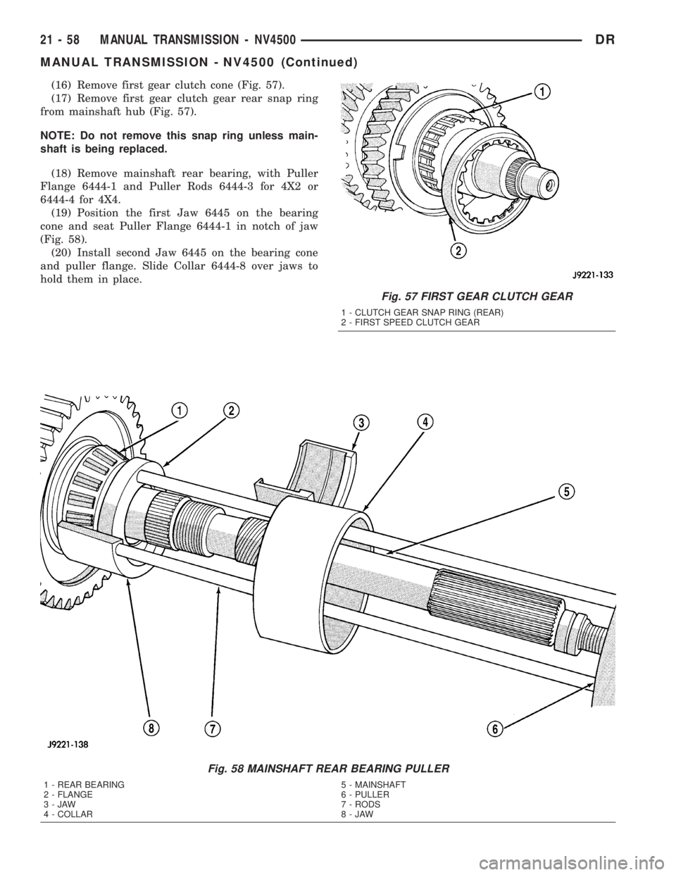
(16) Remove first gear clutch cone (Fig. 57).
(17) Remove first gear clutch gear rear snap ring
from mainshaft hub (Fig. 57).
NOTE: Do not remove this snap ring unless main-
shaft is being replaced.
(18) Remove mainshaft rear bearing, with Puller
Flange 6444-1 and Puller Rods 6444-3 for 4X2 or
6444-4 for 4X4.
(19) Position the first Jaw 6445 on the bearing
cone and seat Puller Flange 6444-1 in notch of jaw
(Fig. 58).
(20) Install second Jaw 6445 on the bearing cone
and puller flange. Slide Collar 6444-8 over jaws to
hold them in place.
Fig. 57 FIRST GEAR CLUTCH GEAR
1 - CLUTCH GEAR SNAP RING (REAR)
2 - FIRST SPEED CLUTCH GEAR
Fig. 58 MAINSHAFT REAR BEARING PULLER
1 - REAR BEARING
2 - FLANGE
3-JAW
4 - COLLAR5 - MAINSHAFT
6 - PULLER
7 - RODS
8-JAW
21 - 58 MANUAL TRANSMISSION - NV4500DR
MANUAL TRANSMISSION - NV4500 (Continued)
Page 1910 of 2895

(e) Install second and third struts in same man-
ner as described in step (d).
(f) Work sleeve upward on hub until struts are
centered and seated in sleeve. Sleeve should be in
neutral position after seating struts.
(34) Install reverse gear and synchro assembly on
mainshaft (Fig. 104). Rotate assembly until stop ring
lugs engage in hub slots and gear drops into seated
position.
(35) Install reverse gear thrust washer (Fig. 105).
(36) Install rear bearing on mainshaft with
Installer 6446. Seat bearing on output shaft and
against thrust washer (Fig. 106).
(37) Install fourth gear stop ring in 3-4 synchro
sleeve (Fig. 107).
(38) Install fourth gear clutch gear in stop ring
(Fig. 108).
(39) Roll gear case onto its left side.
(40) Grip mainshaft at pilot bearing hub and just
behind reverse gear. Then lift assembly and guide
rear of shaft through bearing bore at rear of case.
(41) Continue holding front of shaft but switch
grip at rear to shaft output splines. Lift mainshaft
assembly slightly, align gears and seat assembly in
case.
Fig. 104 REVERSE GEAR
1 - REVERSE GEAR AND SYNCHRO ASSEMBLY
Fig. 105 REVERSE GEAR THRUST WASHER
1 - THRUST WASHER
2 - REVERSE GEAR
Fig. 106 MAINSHAFT REAR BEARING
1 - INSTALLER
2 - MAINSHAFT REAR BEARING
Fig. 107 FOURTH GEAR STOP RING
1 - 3-4 SYNCHRO SLEEVE
2 - FOURTH SPEED STOP RING
Fig. 108 FOURTH GEAR CLUTCH GEAR
1 - FOURTH SPEED CLUTCH GEAR
DRMANUAL TRANSMISSION - NV4500 21 - 71
MANUAL TRANSMISSION - NV4500 (Continued)
Page 1911 of 2895
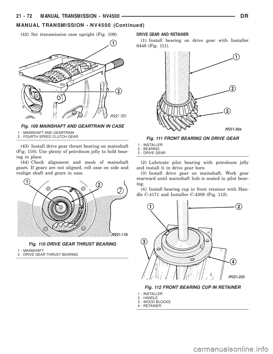
(42) Set transmission case upright (Fig. 109).
(43) Install drive gear thrust bearing on mainshaft
(Fig. 110). Use plenty of petroleum jelly to hold bear-
ing in place.
(44) Check alignment and mesh of mainshaft
gears. If gears are not aligned, roll case on side and
realign shaft and gears in case.DRIVE GEAR AND RETAINER
(1) Install bearing on drive gear with Installer
6448 (Fig. 111).
(2) Lubricate pilot bearing with petroleum jelly
and install it in drive gear bore.
(3) Install drive gear on mainshaft. Work gear
rearward until mainshaft hub is seated in pilot bear-
ing.
(4) Install bearing cup in front retainer with Han-
dle C-4171 and Installer C-4308 (Fig. 112).
Fig. 109 MAINSHAFT AND GEARTRAIN IN CASE
1 - MAINSHAFT AND GEARTRAIN
2 - FOURTH SPEED CLUTCH GEAR
Fig. 110 DRIVE GEAR THRUST BEARING
1 - MAINSHAFT
2 - DRIVE GEAR THRUST BEARING
Fig. 111 FRONT BEARING ON DRIVE GEAR
1 - INSTALLER
2 - BEARING
3 - DRIVE GEAR
Fig. 112 FRONT BEARING CUP IN RETAINER
1 - INSTALLER
2 - HANDLE
3 - WOOD BLOCKS
4 - RETAINER
21 - 72 MANUAL TRANSMISSION - NV4500DR
MANUAL TRANSMISSION - NV4500 (Continued)
Page 1917 of 2895
²release fork ball stud.
²propeller shaft slip yoke.
(2) Apply sealer to threads of bottom PTO cover
bolt and install bolt in case.
(3) Mount transmission on jack and position trans-
mission under vehicle.
(4) Raise transmission until input shaft is centered
in release bearing and clutch disc hub.
(5) Move transmission forward and start input
shaft in release bearing, clutch disc and pilot bush-
ing.
(6) Work transmission forward until seated against
clutch housing. Do not allow transmission to remain
unsupported after input shaft has entered clutch
disc.
(7) Install transmission bolts and tighten to 108
N´m (80 ft. lbs.).
(8) Install transmission mount on transmission or
rear crossmember.
(9) Install rear crossmember.
(10) Remove transmission jack and engine support
fixture.
(11) Position transmission harness wires in clips
on shift cover.
(12) Install clutch slave cylinder and install slave
cylinder shield, if equipped.
(13) Connect speed sensor and backup light switch
wires.
TWO WHEEL DRIVE
(1) Fill transmission with recommended lubricant.
Correct fill level is bottom edge of fill plug hole.
(2) Align and install propeller shaft.
(3) Lower vehicle.
(4) Clean the mating surfaces of shift tower, isola-
tor plate and shift cover with suitable wax and
grease remover.
(5) Apply Mopar Gasket Maker or equivalent to
the sealing surface of the shift cover. Do not over
apply sealant.
(6) Install the isolator plate onto the shift cover,
metal side down.
(7) Install the shift tower onto the isolator plate.
No sealant is necessary between the shift tower and
the isolator plate.
(8) Verify that the shift tower, isolator plate and
the shift tower bushings are properly aligned.
(9) Install the bolts to hold the shift tower to the
isolator plate and the shift cover. Tighten the shift
tower bolts to 10.2-11.25 N´m (7.5-8.3 ft. lbs.).
(10) Install the shift lever extension onto the shift
tower and lever assembly.
(11) Install shift boot and bezel.
(12) Connect battery negative cable.
FOUR WHEEL DRIVE
(1) Install transfer case shift mechanism on trans-
mission.
(2) Install transfer case on transmission jack.
Secure transfer case to jack with safety chains.
(3) Raise jack and align transfer case input gear
with transmission mainshaft.
(4) Move transfer case forward and seat it on
adapter.
(5) Install transfer case nuts and tighten to:
²If 3/8 studs 41-47 N´m (30-35 ft. lbs.).
²If 5/16 studs 30-41 N´m (22-30 ft. lbs.).
(6) Install transfer case shift mechanism to side of
transfer case.
(7) Connect transfer case shift lever to range lever
on transfer case.
(8) Align and connect propeller shafts.
(9) Fill transmission with required lubricant.
Check lubricant level in transfer case and add lubri-
cant if necessary.
(10) Install transfer case skid plate, if equipped
and crossmember. Tighten attaching bolts/nuts to 41
N´m (30 ft. lbs.).
(11) Install exhaust system components.
(12) Lower vehicle.
(13) Clean the mating surfaces of shift tower, iso-
lator plate and shift cover with suitable wax and
grease remover.
(14) Apply Mopar Gasket Maker or equivalent to
the sealing surface of the shift cover. Do not over
apply sealant.
(15) Install the isolator plate onto the shift cover,
metal side down.
(16) Install the shift tower onto the isolator plate.
No sealant is necessary between the shift tower and
the isolator plate.
(17) Verify that the shift tower, isolator plate and
the shift tower bushings are properly aligned.
(18) Install the bolts to hold the shift tower to the
isolator plate and the shift cover. Tighten the shift
tower bolts to 10.2-11.25 N´m (7.5-8.3 ft. lbs.).
(19) Install the shift lever extension onto the shift
tower and lever assembly.
(20) Install shift lever boot and bezel.
(21) Connect battery negative cable.
21 - 78 MANUAL TRANSMISSION - NV4500DR
MANUAL TRANSMISSION - NV4500 (Continued)
Page 1926 of 2895
MANUAL TRANSMISSION - NV5600
TABLE OF CONTENTS
page page
MANUAL TRANSMISSION - NV5600
DESCRIPTION.........................87
OPERATION...........................89
DIAGNOSIS AND TESTING................89
REMOVAL.............................89
DISASSEMBLY.........................90
CLEANING - TRANSMISSION.............104
INSPECTION.........................104
ASSEMBLY...........................105
INSTALLATION........................120
SPECIFICATIONS - NV5600..............122SPECIAL TOOLS.......................122
ADAPTER HOUSING SEAL
REMOVAL............................127
INSTALLATION........................127
EXTENSION HOUSING SEAL
REMOVAL............................127
INSTALLATION........................127
SHIFT COVER
REMOVAL............................128
INSTALLATION........................128
MANUAL TRANSMISSION -
NV5600
DESCRIPTION
The NV5600 is a six speed constant mesh manual
transmission (Fig. 1). All gear ranges including
reverse are synchronized. First and second gears uti-
lize dual cone synchronizers in order to aid shifting.
Sixth gear is an overdrive range. The transmission
uses cast iron for the gear case and extension/
adapter housing and aluminum for the clutch hous-
ing.To drain the trans remove the bottom PTO cover
bolt. Fill the trans through the plug to the rear of the
PTO cover (Fig. 1). Dry fill is approximately 4.5 liters
(9.5 pints) or to the bottom edge of the fill plug hole.
The gear ratios are:GEAR RATIOS
GEAR RATIO
FIRST 5.63:1
SECOND 3.38:1
THIRD 2.04:1
FOURTH 1.39:1
FIFTH 1.00:1
SIXTH 0.73:1
REVERSE 5.63:1
DRMANUAL TRANSMISSION - NV5600 21 - 87
Page 1928 of 2895
IDENTIFICATION
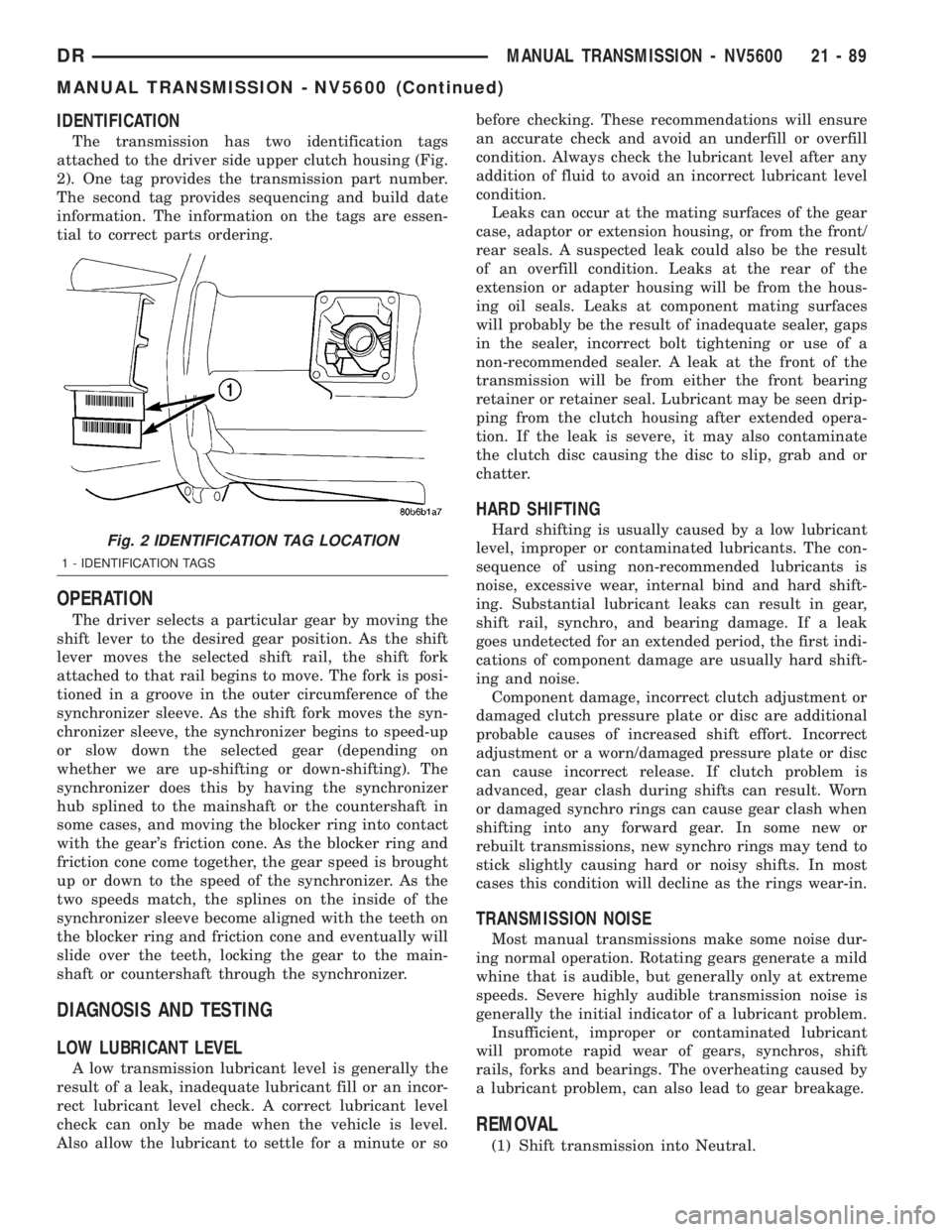
The transmission has two identification tags
attached to the driver side upper clutch housing (Fig.
2). One tag provides the transmission part number.
The second tag provides sequencing and build date
information. The information on the tags are essen-
tial to correct parts ordering.
OPERATION
The driver selects a particular gear by moving the
shift lever to the desired gear position. As the shift
lever moves the selected shift rail, the shift fork
attached to that rail begins to move. The fork is posi-
tioned in a groove in the outer circumference of the
synchronizer sleeve. As the shift fork moves the syn-
chronizer sleeve, the synchronizer begins to speed-up
or slow down the selected gear (depending on
whether we are up-shifting or down-shifting). The
synchronizer does this by having the synchronizer
hub splined to the mainshaft or the countershaft in
some cases, and moving the blocker ring into contact
with the gear's friction cone. As the blocker ring and
friction cone come together, the gear speed is brought
up or down to the speed of the synchronizer. As the
two speeds match, the splines on the inside of the
synchronizer sleeve become aligned with the teeth on
the blocker ring and friction cone and eventually will
slide over the teeth, locking the gear to the main-
shaft or countershaft through the synchronizer.
DIAGNOSIS AND TESTING
LOW LUBRICANT LEVEL
A low transmission lubricant level is generally the
result of a leak, inadequate lubricant fill or an incor-
rect lubricant level check. A correct lubricant level
check can only be made when the vehicle is level.
Also allow the lubricant to settle for a minute or sobefore checking. These recommendations will ensure
an accurate check and avoid an underfill or overfill
condition. Always check the lubricant level after any
addition of fluid to avoid an incorrect lubricant level
condition.
Leaks can occur at the mating surfaces of the gear
case, adaptor or extension housing, or from the front/
rear seals. A suspected leak could also be the result
of an overfill condition. Leaks at the rear of the
extension or adapter housing will be from the hous-
ing oil seals. Leaks at component mating surfaces
will probably be the result of inadequate sealer, gaps
in the sealer, incorrect bolt tightening or use of a
non-recommended sealer. A leak at the front of the
transmission will be from either the front bearing
retainer or retainer seal. Lubricant may be seen drip-
ping from the clutch housing after extended opera-
tion. If the leak is severe, it may also contaminate
the clutch disc causing the disc to slip, grab and or
chatter.
HARD SHIFTING
Hard shifting is usually caused by a low lubricant
level, improper or contaminated lubricants. The con-
sequence of using non-recommended lubricants is
noise, excessive wear, internal bind and hard shift-
ing. Substantial lubricant leaks can result in gear,
shift rail, synchro, and bearing damage. If a leak
goes undetected for an extended period, the first indi-
cations of component damage are usually hard shift-
ing and noise.
Component damage, incorrect clutch adjustment or
damaged clutch pressure plate or disc are additional
probable causes of increased shift effort. Incorrect
adjustment or a worn/damaged pressure plate or disc
can cause incorrect release. If clutch problem is
advanced, gear clash during shifts can result. Worn
or damaged synchro rings can cause gear clash when
shifting into any forward gear. In some new or
rebuilt transmissions, new synchro rings may tend to
stick slightly causing hard or noisy shifts. In most
cases this condition will decline as the rings wear-in.
TRANSMISSION NOISE
Most manual transmissions make some noise dur-
ing normal operation. Rotating gears generate a mild
whine that is audible, but generally only at extreme
speeds. Severe highly audible transmission noise is
generally the initial indicator of a lubricant problem.
Insufficient, improper or contaminated lubricant
will promote rapid wear of gears, synchros, shift
rails, forks and bearings. The overheating caused by
a lubricant problem, can also lead to gear breakage.
REMOVAL
(1) Shift transmission into Neutral.
Fig. 2 IDENTIFICATION TAG LOCATION
1 - IDENTIFICATION TAGS
DRMANUAL TRANSMISSION - NV5600 21 - 89
MANUAL TRANSMISSION - NV5600 (Continued)