2003 DODGE RAM 5 speed manual transmission
[x] Cancel search: 5 speed manual transmissionPage 2295 of 2895
1-2 SHIFT VALVE
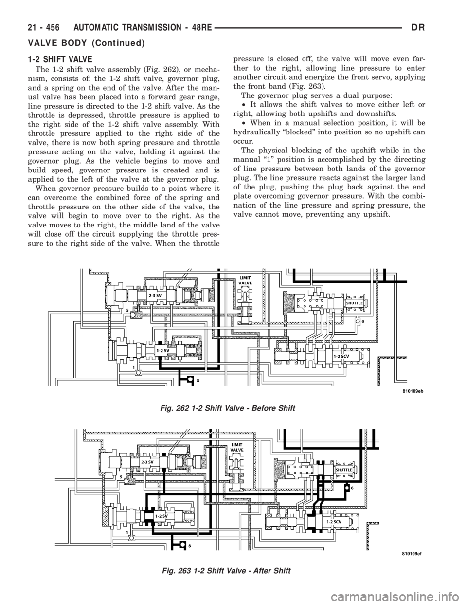
The 1-2 shift valve assembly (Fig. 262), or mecha-
nism, consists of: the 1-2 shift valve, governor plug,
and a spring on the end of the valve. After the man-
ual valve has been placed into a forward gear range,
line pressure is directed to the 1-2 shift valve. As the
throttle is depressed, throttle pressure is applied to
the right side of the 1-2 shift valve assembly. With
throttle pressure applied to the right side of the
valve, there is now both spring pressure and throttle
pressure acting on the valve, holding it against the
governor plug. As the vehicle begins to move and
build speed, governor pressure is created and is
applied to the left of the valve at the governor plug.
When governor pressure builds to a point where it
can overcome the combined force of the spring and
throttle pressure on the other side of the valve, the
valve will begin to move over to the right. As the
valve moves to the right, the middle land of the valve
will close off the circuit supplying the throttle pres-
sure to the right side of the valve. When the throttlepressure is closed off, the valve will move even far-
ther to the right, allowing line pressure to enter
another circuit and energize the front servo, applying
the front band (Fig. 263).
The governor plug serves a dual purpose:
²It allows the shift valves to move either left or
right, allowing both upshifts and downshifts.
²When in a manual selection position, it will be
hydraulically ªblockedº into position so no upshift can
occur.
The physical blocking of the upshift while in the
manual ª1º position is accomplished by the directing
of line pressure between both lands of the governor
plug. The line pressure reacts against the larger land
of the plug, pushing the plug back against the end
plate overcoming governor pressure. With the combi-
nation of the line pressure and spring pressure, the
valve cannot move, preventing any upshift.
Fig. 262 1-2 Shift Valve - Before Shift
Fig. 263 1-2 Shift Valve - After Shift
21 - 456 AUTOMATIC TRANSMISSION - 48REDR
VALVE BODY (Continued)
Page 2297 of 2895
2-3 SHIFT VALVE
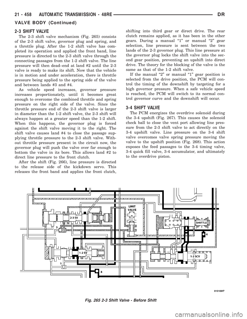
The 2-3 shift valve mechanism (Fig. 265) consists
of the 2-3 shift valve, governor plug and spring, and
a throttle plug. After the 1-2 shift valve has com-
pleted its operation and applied the front band, line
pressure is directed to the 2-3 shift valve through the
connecting passages from the 1-2 shift valve. The line
pressure will then dead±end at land #2 until the 2-3
valve is ready to make its shift. Now that the vehicle
is in motion and under acceleration, there is throttle
pressure being applied to the spring side of the valve
and between lands #3 and #4.
As vehicle speed increases, governor pressure
increases proportionately, until it becomes great
enough to overcome the combined throttle and spring
pressure on the right side of the valve. Since the
throttle pressure end of the 2-3 shift valve is larger
in diameter than the 1-2 shift valve, the 2-3 shift will
always happen at a greater speed than the 1-2 shift.
When this happens, the governor plug is forced
against the shift valve moving it to the right. The
shift valve causes land #4 to close the passage sup-
plying throttle pressure to the 2-3 shift valve. With-
out throttle pressure present in the circuit now, the
governor plug will push the valve over far enough to
bottom the valve in its bore. This allows land #2 to
direct line pressure to the front clutch.
After the shift (Fig. 266), line pressure is directed
to the release side of the kickdown servo. This
releases the front band and applies the front clutch,shifting into third gear or direct drive. The rear
clutch remains applied, as it has been in the other
gears. During a manual ª1º or manual ª2º gear
selection, line pressure is sent between the two
lands of the 2-3 governor plug. This line pressure at
the governor plug locks the shift valve into the sec-
ond gear position, preventing an upshift into direct
drive. The theory for the blocking of the valve is the
same as that of the 1-2 shift valve.
If the manual ª2º or manual ª1º gear position is
selected from the drive position, the PCM will con-
trol the timing of the downshift by targeting for a
high governor pressure. When a safe vehicle speed
is reached, the PCM will switch to its normal con-
trol governor curve and the downshift will occur.
3-4 SHIFT VALVE
The PCM energizes the overdrive solenoid during
the 3-4 upshift (Fig. 267). This causes the solenoid
check ball to close the vent port allowing line pres-
sure from the 2-3 shift valve to act directly on the
3-4 upshift valve. Line pressure on the 3-4 shift
valve overcomes valve spring pressure moving the
valve to the upshift position (Fig. 268). This action
exposes the feed passages to the 3-4 timing valve,
3-4 quick fill valve, 3-4 accumulator, and ultimately
to the overdrive piston.
Fig. 265 2-3 Shift Valve - Before Shift
21 - 458 AUTOMATIC TRANSMISSION - 48REDR
VALVE BODY (Continued)
Page 2336 of 2895
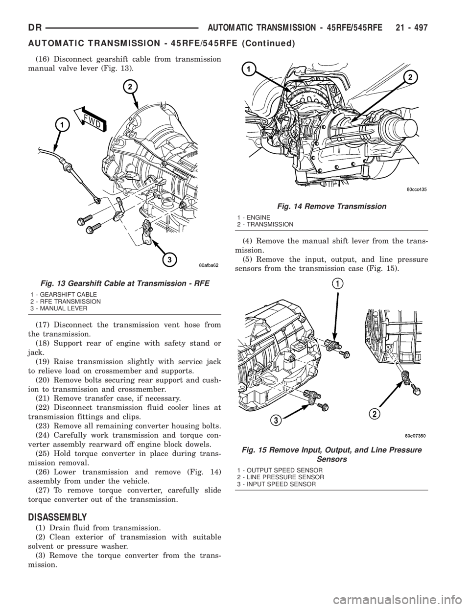
(16) Disconnect gearshift cable from transmission
manual valve lever (Fig. 13).
(17) Disconnect the transmission vent hose from
the transmission.
(18) Support rear of engine with safety stand or
jack.
(19) Raise transmission slightly with service jack
to relieve load on crossmember and supports.
(20) Remove bolts securing rear support and cush-
ion to transmission and crossmember.
(21) Remove transfer case, if necessary.
(22) Disconnect transmission fluid cooler lines at
transmission fittings and clips.
(23) Remove all remaining converter housing bolts.
(24) Carefully work transmission and torque con-
verter assembly rearward off engine block dowels.
(25) Hold torque converter in place during trans-
mission removal.
(26) Lower transmission and remove (Fig. 14)
assembly from under the vehicle.
(27) To remove torque converter, carefully slide
torque converter out of the transmission.
DISASSEMBLY
(1) Drain fluid from transmission.
(2) Clean exterior of transmission with suitable
solvent or pressure washer.
(3) Remove the torque converter from the trans-
mission.(4) Remove the manual shift lever from the trans-
mission.
(5) Remove the input, output, and line pressure
sensors from the transmission case (Fig. 15).
Fig. 13 Gearshift Cable at Transmission - RFE
1 - GEARSHIFT CABLE
2 - RFE TRANSMISSION
3 - MANUAL LEVER
Fig. 14 Remove Transmission
1 - ENGINE
2 - TRANSMISSION
Fig. 15 Remove Input, Output, and Line Pressure
Sensors
1 - OUTPUT SPEED SENSOR
2 - LINE PRESSURE SENSOR
3 - INPUT SPEED SENSOR
DRAUTOMATIC TRANSMISSION - 45RFE/545RFE 21 - 497
AUTOMATIC TRANSMISSION - 45RFE/545RFE (Continued)
Page 2348 of 2895
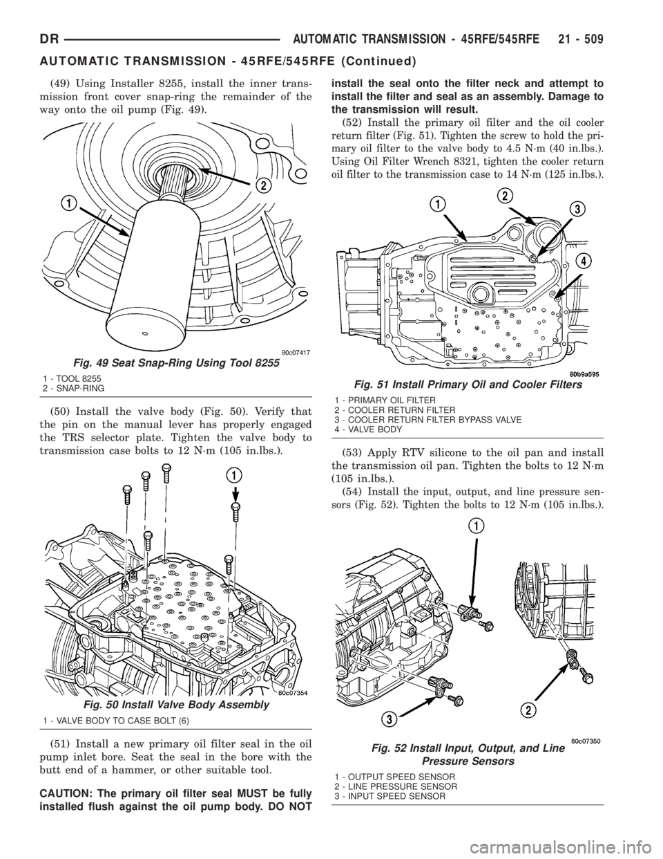
(49) Using Installer 8255, install the inner trans-
mission front cover snap-ring the remainder of the
way onto the oil pump (Fig. 49).
(50) Install the valve body (Fig. 50). Verify that
the pin on the manual lever has properly engaged
the TRS selector plate. Tighten the valve body to
transmission case bolts to 12 N´m (105 in.lbs.).
(51) Install a new primary oil filter seal in the oil
pump inlet bore. Seat the seal in the bore with the
butt end of a hammer, or other suitable tool.
CAUTION: The primary oil filter seal MUST be fully
installed flush against the oil pump body. DO NOTinstall the seal onto the filter neck and attempt to
install the filter and seal as an assembly. Damage to
the transmission will result.
(52)
Install the primary oil filter and the oil cooler
return filter (Fig. 51). Tighten the screw to hold the pri-
mary oil filter to the valve body to 4.5 N´m (40 in.lbs.).
Using Oil Filter Wrench 8321, tighten the cooler return
oil filter to the transmission case to 14 N´m (125 in.lbs.).
(53) Apply RTV silicone to the oil pan and install
the transmission oil pan. Tighten the bolts to 12 N´m
(105 in.lbs.).
(54)
Install the input, output, and line pressure sen-
sors (Fig. 52). Tighten the bolts to 12 N´m (105 in.lbs.).
Fig. 49 Seat Snap-Ring Using Tool 8255
1 - TOOL 8255
2 - SNAP-RING
Fig. 50 Install Valve Body Assembly
1 - VALVE BODY TO CASE BOLT (6)
Fig. 51 Install Primary Oil and Cooler Filters
1 - PRIMARY OIL FILTER
2 - COOLER RETURN FILTER
3 - COOLER RETURN FILTER BYPASS VALVE
4 - VALVE BODY
Fig. 52 Install Input, Output, and Line
Pressure Sensors
1 - OUTPUT SPEED SENSOR
2 - LINE PRESSURE SENSOR
3 - INPUT SPEED SENSOR
DRAUTOMATIC TRANSMISSION - 45RFE/545RFE 21 - 509
AUTOMATIC TRANSMISSION - 45RFE/545RFE (Continued)
Page 2373 of 2895
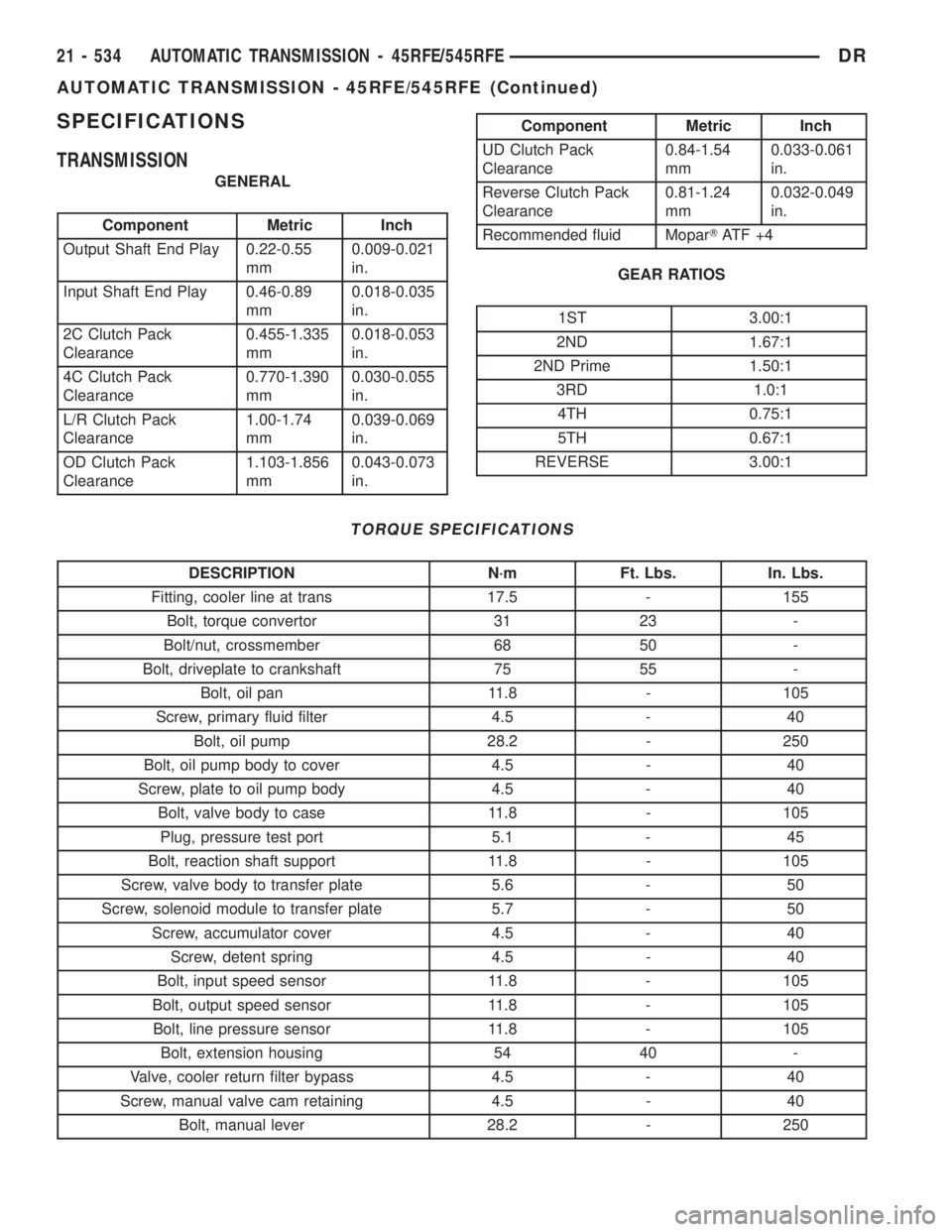
SPECIFICATIONS
TRANSMISSION
GENERAL
Component Metric Inch
Output Shaft End Play 0.22-0.55
mm0.009-0.021
in.
Input Shaft End Play 0.46-0.89
mm0.018-0.035
in.
2C Clutch Pack
Clearance0.455-1.335
mm0.018-0.053
in.
4C Clutch Pack
Clearance0.770-1.390
mm0.030-0.055
in.
L/R Clutch Pack
Clearance1.00-1.74
mm0.039-0.069
in.
OD Clutch Pack
Clearance1.103-1.856
mm0.043-0.073
in.
Component Metric Inch
UD Clutch Pack
Clearance0.84-1.54
mm0.033-0.061
in.
Reverse Clutch Pack
Clearance0.81-1.24
mm0.032-0.049
in.
Recommended fluid MoparTAT F + 4
GEAR RATIOS
1ST 3.00:1
2ND 1.67:1
2ND Prime 1.50:1
3RD 1.0:1
4TH 0.75:1
5TH 0.67:1
REVERSE 3.00:1
TORQUE SPECIFICATIONS
DESCRIPTION N´m Ft. Lbs. In. Lbs.
Fitting, cooler line at trans 17.5 - 155
Bolt, torque convertor 31 23 -
Bolt/nut, crossmember 68 50 -
Bolt, driveplate to crankshaft 75 55 -
Bolt, oil pan 11.8 - 105
Screw, primary fluid filter 4.5 - 40
Bolt, oil pump 28.2 - 250
Bolt, oil pump body to cover 4.5 - 40
Screw, plate to oil pump body 4.5 - 40
Bolt, valve body to case 11.8 - 105
Plug, pressure test port 5.1 - 45
Bolt, reaction shaft support 11.8 - 105
Screw, valve body to transfer plate 5.6 - 50
Screw, solenoid module to transfer plate 5.7 - 50
Screw, accumulator cover 4.5 - 40
Screw, detent spring 4.5 - 40
Bolt, input speed sensor 11.8 - 105
Bolt, output speed sensor 11.8 - 105
Bolt, line pressure sensor 11.8 - 105
Bolt, extension housing 54 40 -
Valve, cooler return filter bypass 4.5 - 40
Screw, manual valve cam retaining 4.5 - 40
Bolt, manual lever 28.2 - 250
21 - 534 AUTOMATIC TRANSMISSION - 45RFE/545RFEDR
AUTOMATIC TRANSMISSION - 45RFE/545RFE (Continued)
Page 2413 of 2895
(5) Install the number 9 bearing onto the front of
the reverse planetary carrier with the outer race
toward the carrier and the inner race facing upward
(Fig. 116).
(6) Install the reverse planetary gear carrier into
the input carrier (Fig. 116).
(7) Install the input annulus gear into the input
carrier (Fig. 116).
(8) Install the snap-ring to hold the input annulus
gear into the input carrier (Fig. 116).
SHIFT MECHANISM
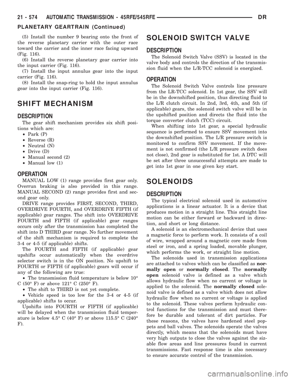
DESCRIPTION
The gear shift mechanism provides six shift posi-
tions which are:
²Park (P)
²Reverse (R)
²Neutral (N)
²Drive (D)
²Manual second (2)
²Manual low (1)
OPERATION
MANUAL LOW (1) range provides first gear only.
Overrun braking is also provided in this range.
MANUAL SECOND (2) range provides first and sec-
ond gear only.
DRIVE range provides FIRST, SECOND, THIRD,
OVERDRIVE FOURTH, and OVERDRIVE FIFTH (if
applicable) gear ranges. The shift into OVERDRIVE
FOURTH and FIFTH (if applicable) gear ranges
occurs only after the transmission has completed the
shift into D THIRD gear range. No further movement
of the shift mechanism is required to complete the
3-4 or 4-5 (if applicable) shifts.
The FOURTH and FIFTH (if applicable) gear
upshifts occur automatically when the overdrive
selector switch is in the ON position. No upshift to
FOURTH or FIFTH (if applicable) gears will occur if
any of the following are true:
²The transmission fluid temperature is below 10É
C (50É F) or above 121É C (250É F).
²The shift to THIRD is not yet complete.
²Vehicle speed is too low for the 3-4 or 4-5 (if
applicable) shifts to occur.
Upshifts into FOURTH or FIFTH (if applicable)
will be delayed when the transmission fluid temper-
ature is below 4.5É C (40É F) or above 115.5É C (240É
F).
SOLENOID SWITCH VALVE
DESCRIPTION
The Solenoid Switch Valve (SSV) is located in the
valve body and controls the direction of the transmis-
sion fluid when the L/R-TCC solenoid is energized.
OPERATION
The Solenoid Switch Valve controls line pressure
from the LR-TCC solenoid. In 1st gear, the SSV will
be in the downshifted position, thus directing fluid to
the L/R clutch circuit. In 2nd, 3rd, 4th, and 5th (if
applicable) gears, the solenoid switch valve will be in
the upshifted position and directs the fluid into the
torque converter clutch (TCC) circuit.
When shifting into 1st gear, a special hydraulic
sequence is performed to ensure SSV movement into
the downshifted position. The L/R pressure switch is
monitored to confirm SSV movement. If the move-
ment is not confirmed (the L/R pressure switch does
not close), 2nd gear is substituted for 1st. A DTC will
be set after three unsuccessful attempts are made to
get into 1st gear in one given key start.
SOLENOIDS
DESCRIPTION
The typical electrical solenoid used in automotive
applications is a linear actuator. It is a device that
produces motion in a straight line. This straight line
motion can be either forward or backward in direc-
tion, and short or long distance.
A solenoid is an electromechanical device that uses
a magnetic force to perform work. It consists of a coil
of wire, wrapped around a magnetic core made from
steel or iron, and a spring loaded, movable plunger,
which performs the work, or straight line motion.
The solenoids used in transmission applications
are attached to valves which can be classified asnor-
mally openornormally closed. Thenormally
opensolenoid valve is defined as a valve which
allows hydraulic flow when no current or voltage is
applied to the solenoid. Thenormally closedsole-
noid valve is defined as a valve which does not allow
hydraulic flow when no current or voltage is applied
to the solenoid. These valves perform hydraulic con-
trol functions for the transmission and must there-
fore be durable and tolerant of dirt particles. For
these reasons, the valves have hardened steel pop-
pets and ball valves. The solenoids operate the valves
directly, which means that the solenoids must have
very high outputs to close the valves against the siz-
able flow areas and line pressures found in current
transmissions. Fast response time is also necessary
to ensure accurate control of the transmission.
21 - 574 AUTOMATIC TRANSMISSION - 45RFE/545RFEDR
PLANETARY GEARTRAIN (Continued)
Page 2421 of 2895
TRANSMISSION SOLENOID/
TRS ASSEMBLY
DESCRIPTION
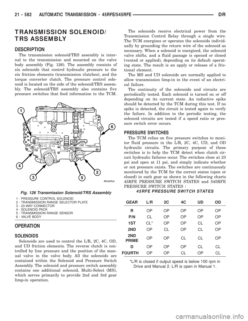
The transmission solenoid/TRS assembly is inter-
nal to the transmission and mounted on the valve
body assembly (Fig. 126). The assembly consists of
six solenoids that control hydraulic pressure to the
six friction elements (transmission clutches), and the
torque converter clutch. The pressure control sole-
noid is located on the side of the solenoid/TRS assem-
bly. The solenoid/TRS assembly also contains five
pressure switches that feed information to the TCM.
OPERATION
SOLENOIDS
Solenoids are used to control the L/R, 2C, 4C, OD,
and UD friction elements. The reverse clutch is con-
trolled by line pressure and the position of the man-
ual valve in the valve body. All the solenoids are
contained within the Solenoid and Pressure Switch
Assembly. The solenoid and pressure switch assembly
contains one additional solenoid, Multi-Select (MS),
which serves primarily to provide 2nd and 3rd gear
limp-in operation.The solenoids receive electrical power from the
Transmission Control Relay through a single wire.
The TCM energizes or operates the solenoids individ-
ually by grounding the return wire of the solenoid as
necessary. When a solenoid is energized, the solenoid
valve shifts, and a fluid passage is opened or closed
(vented or applied), depending on its default operat-
ing state. The result is an apply or release of a fric-
tional element.
The MS and UD solenoids are normally applied to
allow transmission limp-in in the event of an electri-
cal failure.
The continuity of the solenoids and circuits are
periodically tested. Each solenoid is turned on or off
depending on its current state. An inductive spike
should be detected by the TCM during this test. If no
spike is detected, the circuit is tested again to verify
the failure. In addition to the periodic testing, the
solenoid circuits are tested if a speed ratio or pres-
sure switch error occurs.
PRESSURE SWITCHES
The TCM relies on five pressure switches to moni-
tor fluid pressure in the L/R, 2C, 4C, UD, and OD
hydraulic circuits. The primary purpose of these
switches is to help the TCM detect when clutch cir-
cuit hydraulic failures occur. The switches close at 23
psi and open at 11 psi, and simply indicate whether
or not pressure exists. The switches are continuously
monitored by the TCM for the correct states (open or
closed) in each gear as shown in the following charts
45RFE PRESSURE SWITCH STATES and 545RFE
PRESSURE SWITCH STATES :
45RFE PRESSURE SWITCH STATES
GEAR L/R 2C 4C UD OD
ROP OP OP OP OP
P/NCL OP OP OP OP
1STCL* OP OP CL OP
2NDOP CL OP CL OP
2ND
PRIMEOP OP CL CL OP
DOP OP OP CL CL
FOURTHOP OP CL OP CL
*L/R is closed if output speed is below 100 rpm in
Drive and Manual 2. L/R is open in Manual 1.
Fig. 126 Transmission Solenoid/TRS Assembly
1 - PRESSURE CONTROL SOLENOID
2 - TRANSMISSION RANGE SELECTOR PLATE
3 - 23-WAY CONNECTOR
4 - SOLENOID PACK
5 - TRANSMISSION RANGE SENSOR
6 - VALVE BODY
21 - 582 AUTOMATIC TRANSMISSION - 45RFE/545RFEDR
Page 2422 of 2895
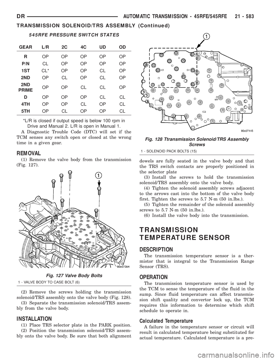
545RFE PRESSURE SWITCH STATES
GEAR L/R 2C 4C UD OD
ROP OP OP OP OP
P/NCL OP OP OP OP
1STCL* OP OP CL OP
2NDOP CL OP CL OP
2ND
PRIMEOP OP CL CL OP
DOP OP OP CL CL
4THOP OP CL OP CL
5THOP CL OP OP CL
*L/R is closed if output speed is below 100 rpm in
Drive and Manual 2. L/R is open in Manual 1.
A Diagnostic Trouble Code (DTC) will set if the
TCM senses any switch open or closed at the wrong
time in a given gear.
REMOVAL
(1) Remove the valve body from the transmission
(Fig. 127).
(2) Remove the screws holding the transmission
solenoid/TRS assembly onto the valve body (Fig. 128).
(3) Separate the transmission solenoid/TRS assem-
bly from the valve body.
INSTALLATION
(1) Place TRS selector plate in the PARK position.
(2) Position the transmission solenoid/TRS assem-
bly onto the valve body. Be sure that both alignmentdowels are fully seated in the valve body and that
the TRS switch contacts are properly positioned in
the selector plate
(3) Install the screws to hold the transmission
solenoid/TRS assembly onto the valve body.
(4) Tighten the solenoid assembly screws adjacent
to the arrows cast into the bottom of the valve body
first. Tighten the screws to 5.7 N´m (50 in.lbs.).
(5) Tighten the remainder of the solenoid assembly
screws to 5.7 N´m (50 in.lbs.).
(6) Install the valve body into the transmission.
TRANSMISSION
TEMPERATURE SENSOR
DESCRIPTION
The transmission temperature sensor is a ther-
mistor that is integral to the Transmission Range
Sensor (TRS).
OPERATION
The transmission temperature sensor is used by
the TCM to sense the temperature of the fluid in the
sump. Since fluid temperature can affect transmis-
sion shift quality and convertor lock up, the TCM
requires this information to determine which shift
schedule to operate in.
Calculated Temperature
A failure in the temperature sensor or circuit will
result in calculated temperature being substituted for
actual temperature. Calculated temperature is a pre-
Fig. 127 Valve Body Bolts
1 - VALVE BODY TO CASE BOLT (6)
Fig. 128 Ttransmission Solenoid/TRS Assembly
Screws
1 - SOLENOID PACK BOLTS (15)
DRAUTOMATIC TRANSMISSION - 45RFE/545RFE 21 - 583
TRANSMISSION SOLENOID/TRS ASSEMBLY (Continued)