2003 DODGE RAM 5 speed manual transmission
[x] Cancel search: 5 speed manual transmissionPage 1976 of 2895
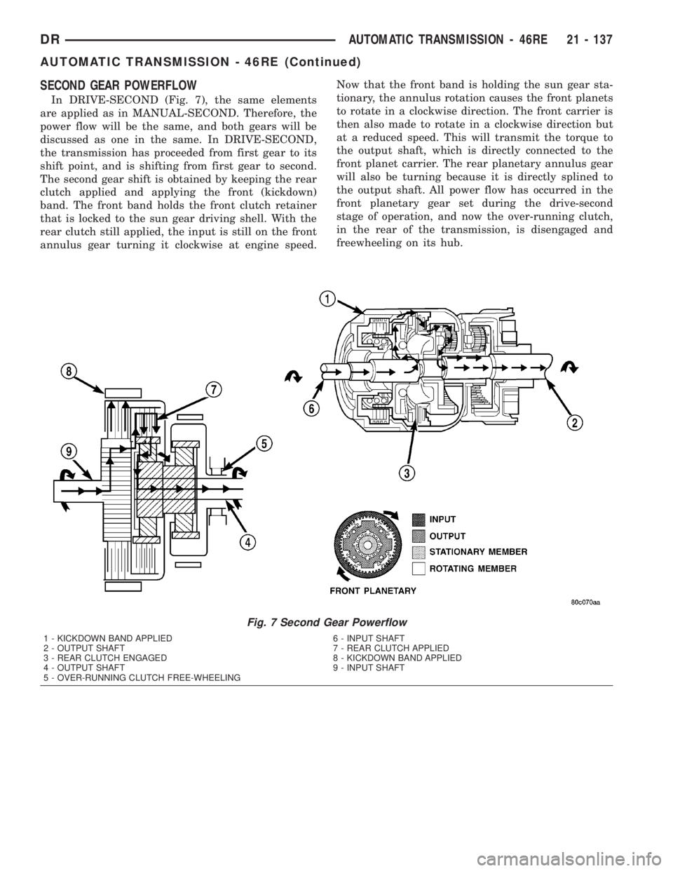
SECOND GEAR POWERFLOW
In DRIVE-SECOND (Fig. 7), the same elements
are applied as in MANUAL-SECOND. Therefore, the
power flow will be the same, and both gears will be
discussed as one in the same. In DRIVE-SECOND,
the transmission has proceeded from first gear to its
shift point, and is shifting from first gear to second.
The second gear shift is obtained by keeping the rear
clutch applied and applying the front (kickdown)
band. The front band holds the front clutch retainer
that is locked to the sun gear driving shell. With the
rear clutch still applied, the input is still on the front
annulus gear turning it clockwise at engine speed.Now that the front band is holding the sun gear sta-
tionary, the annulus rotation causes the front planets
to rotate in a clockwise direction. The front carrier is
then also made to rotate in a clockwise direction but
at a reduced speed. This will transmit the torque to
the output shaft, which is directly connected to the
front planet carrier. The rear planetary annulus gear
will also be turning because it is directly splined to
the output shaft. All power flow has occurred in the
front planetary gear set during the drive-second
stage of operation, and now the over-running clutch,
in the rear of the transmission, is disengaged and
freewheeling on its hub.
Fig. 7 Second Gear Powerflow
1 - KICKDOWN BAND APPLIED 6 - INPUT SHAFT
2 - OUTPUT SHAFT 7 - REAR CLUTCH APPLIED
3 - REAR CLUTCH ENGAGED 8 - KICKDOWN BAND APPLIED
4 - OUTPUT SHAFT 9 - INPUT SHAFT
5 - OVER-RUNNING CLUTCH FREE-WHEELING
DRAUTOMATIC TRANSMISSION - 46RE 21 - 137
AUTOMATIC TRANSMISSION - 46RE (Continued)
Page 2092 of 2895
ASSEMBLY
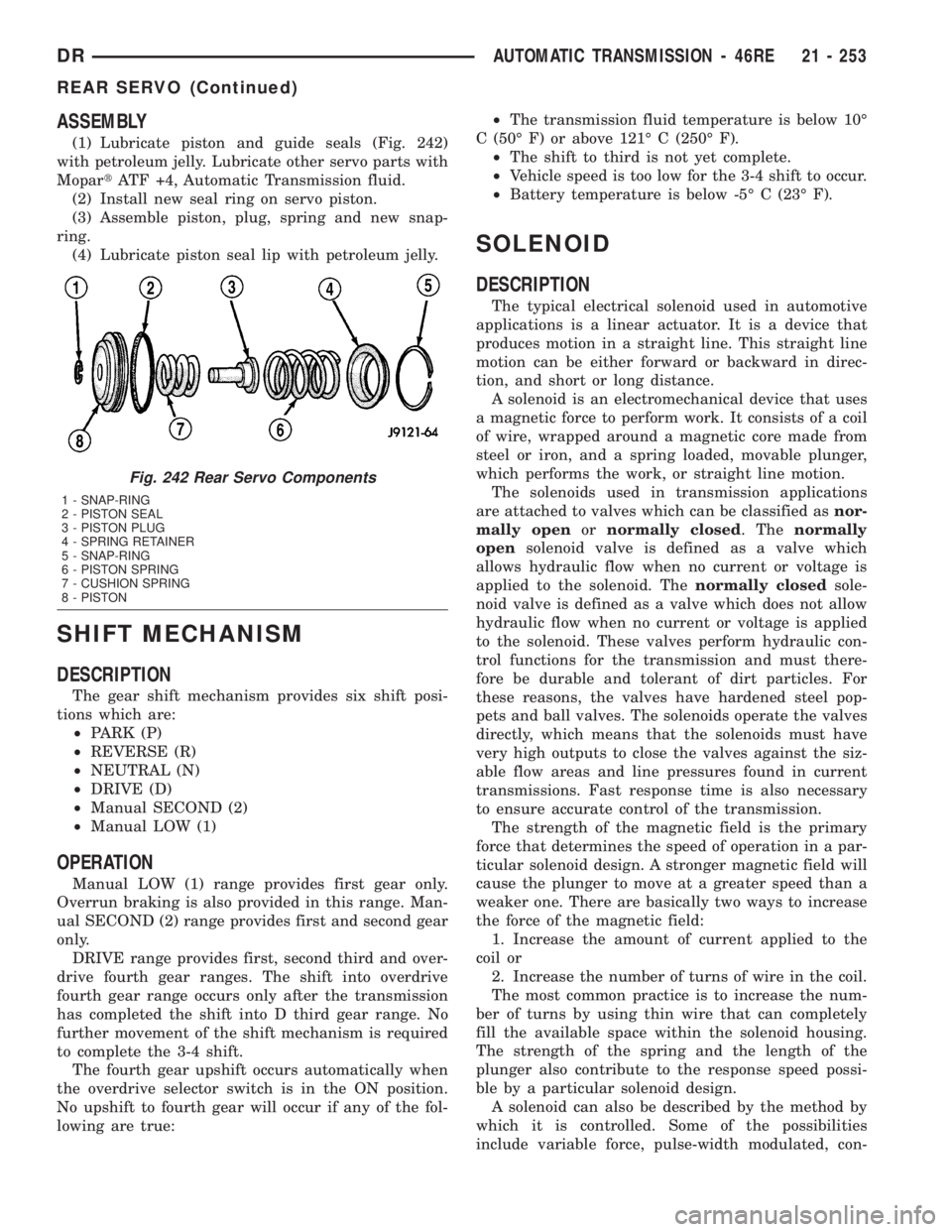
(1) Lubricate piston and guide seals (Fig. 242)
with petroleum jelly. Lubricate other servo parts with
MopartATF +4, Automatic Transmission fluid.
(2) Install new seal ring on servo piston.
(3) Assemble piston, plug, spring and new snap-
ring.
(4) Lubricate piston seal lip with petroleum jelly.
SHIFT MECHANISM
DESCRIPTION
The gear shift mechanism provides six shift posi-
tions which are:
²PARK (P)
²REVERSE (R)
²NEUTRAL (N)
²DRIVE (D)
²Manual SECOND (2)
²Manual LOW (1)
OPERATION
Manual LOW (1) range provides first gear only.
Overrun braking is also provided in this range. Man-
ual SECOND (2) range provides first and second gear
only.
DRIVE range provides first, second third and over-
drive fourth gear ranges. The shift into overdrive
fourth gear range occurs only after the transmission
has completed the shift into D third gear range. No
further movement of the shift mechanism is required
to complete the 3-4 shift.
The fourth gear upshift occurs automatically when
the overdrive selector switch is in the ON position.
No upshift to fourth gear will occur if any of the fol-
lowing are true:²The transmission fluid temperature is below 10É
C (50É F) or above 121É C (250É F).
²The shift to third is not yet complete.
²Vehicle speed is too low for the 3-4 shift to occur.
²Battery temperature is below -5É C (23É F).
SOLENOID
DESCRIPTION
The typical electrical solenoid used in automotive
applications is a linear actuator. It is a device that
produces motion in a straight line. This straight line
motion can be either forward or backward in direc-
tion, and short or long distance.
A solenoid is an electromechanical device that uses
a magnetic force to perform work. It consists of a coil
of wire, wrapped around a magnetic core made from
steel or iron, and a spring loaded, movable plunger,
which performs the work, or straight line motion.
The solenoids used in transmission applications
are attached to valves which can be classified asnor-
mally openornormally closed. Thenormally
opensolenoid valve is defined as a valve which
allows hydraulic flow when no current or voltage is
applied to the solenoid. Thenormally closedsole-
noid valve is defined as a valve which does not allow
hydraulic flow when no current or voltage is applied
to the solenoid. These valves perform hydraulic con-
trol functions for the transmission and must there-
fore be durable and tolerant of dirt particles. For
these reasons, the valves have hardened steel pop-
pets and ball valves. The solenoids operate the valves
directly, which means that the solenoids must have
very high outputs to close the valves against the siz-
able flow areas and line pressures found in current
transmissions. Fast response time is also necessary
to ensure accurate control of the transmission.
The strength of the magnetic field is the primary
force that determines the speed of operation in a par-
ticular solenoid design. A stronger magnetic field will
cause the plunger to move at a greater speed than a
weaker one. There are basically two ways to increase
the force of the magnetic field:
1. Increase the amount of current applied to the
coil or
2. Increase the number of turns of wire in the coil.
The most common practice is to increase the num-
ber of turns by using thin wire that can completely
fill the available space within the solenoid housing.
The strength of the spring and the length of the
plunger also contribute to the response speed possi-
ble by a particular solenoid design.
A solenoid can also be described by the method by
which it is controlled. Some of the possibilities
include variable force, pulse-width modulated, con-
Fig. 242 Rear Servo Components
1 - SNAP-RING
2 - PISTON SEAL
3 - PISTON PLUG
4 - SPRING RETAINER
5 - SNAP-RING
6 - PISTON SPRING
7 - CUSHION SPRING
8 - PISTON
DRAUTOMATIC TRANSMISSION - 46RE 21 - 253
REAR SERVO (Continued)
Page 2111 of 2895
OPERATION
NOTE: Refer to the Hydraulic Schematics for a visual
aid in determining valve location, operation and design.
CHECK BALLS
CHECK BALL
NUMBERDESCRIPTION
1 Allows either the manual valve to put line pressure on the 1-2 governor plug or the KD Valve to
put WOT line pressure on the 1-2 governor plug.
2 Allows either the manual valve to put line pressure on the 2-3 governor plug or the KD Valve to
put WOT line pressure on the 2-3 governor plug.
3 Allows either the Reverse circuit or the 3rd gear circuit to pressurize the front clutch.
4 Allows either the Manual Low circuit from the Manual Valve or the Reverse from the Manual
Valve circuit to pressurize the rear servo.
5 Directs line pressure to the spring end of the 2-3 shift valve in either Manual Low or Manual
2nd, forcing the downshift to 2nd gear regardless of governor pressure.
6 Provides a by-pass around the front servo orifice so that the servo can release quickly.
7 Provides a by-pass around the rear clutch orifice so that the clutch can release quickly.
8 Directs reverse line pressure through an orifice to the throttle valve eliminating the extra
leakage and insuring that Reverse line pressure pressure will be sufficient.
9 Provides a by-pass around the rear servo orifice so that the servo can release quickly.
10 Allows the lockup clutch to used at WOT in 3rd gear by putting line pressure from the 3-4
Timing Valve on the interlock area of the 2-3 shift valve, thereby preventing a 3rd gear Lock-up
to 2nd gear kickdown.
REGULATOR VALVE
The pressure regulator valve is needed to control
the hydraulic pressure within the system and reduce
the amount of heat produced in the fluid. The pres-
sure regulator valve is located in the valve body near
the manual valve. The pressure regulator valve train
controls the maximum pressure in the lines by
metering the dumping of fluid back into the sump.
Regulated pressure is referred to as ªline pressure.º
The regulator valve (Fig. 271) has a spring on one
end that pushes the valve to the left. This closes a
dump (vent) that is used to lower pressure. The closing
of the dump will cause the oil pressure to increase. Oil
pressure on the opposite end of the valve pushes the
valve to the right, opening the dump and lowering oil
pressure. The result is spring pressure working against
oil pressure to maintain the oil at specific pressures.
With the engine running, fluid flows from the pump to
the pressure regulator valve, manual valve, and the
interconnected circuits. As fluid is sent through pas-
sages to the regulator valve, the pressure pushes the
valve to the right against the large spring. It is also
sent to the reaction areas on the left side of the throttle
pressure plug and the line pressure plug. With the gearselector in the PARK position, fluid recirculates through
the regulator and manual valves back to the sump.
Meanwhile, the torque converter is filled slowly. In
all other gear positions (Fig. 272), fluid flows
between two right side lands to the switch valve and
torque converter. At low pump speeds, the flow is
controlled by the pressure valve groove to reduce
pressure to the torque converter. After the torque
converter and switch valve fill with fluid, the switch
valve becomes the controlling metering device for
torque converter pressure. The regulator valve then
begins to control the line pressure for the other
transmission circuits. The balance of the fluid pres-
sure pushing the valve to the right and the spring
pressure pushing to the left determines the size of
the metering passage at land #2 (land #1 being at
the far right of the valve in the diagram). As fluid
leaks past the land, it moves into a groove connected
to the filter or sump. As the land meters the fluid to
the sump, it causes the pressure to reduce and the
spring decreases the size of the metering passage.
When the size of the metering passage is reduced,
the pressure rises again and the size of the land is
increased again. Pressure is regulated by this con-
stant balance of hydraulic and spring pressure.
21 - 272 AUTOMATIC TRANSMISSION - 46REDR
VALVE BODY (Continued)
Page 2117 of 2895
1-2 SHIFT VALVE
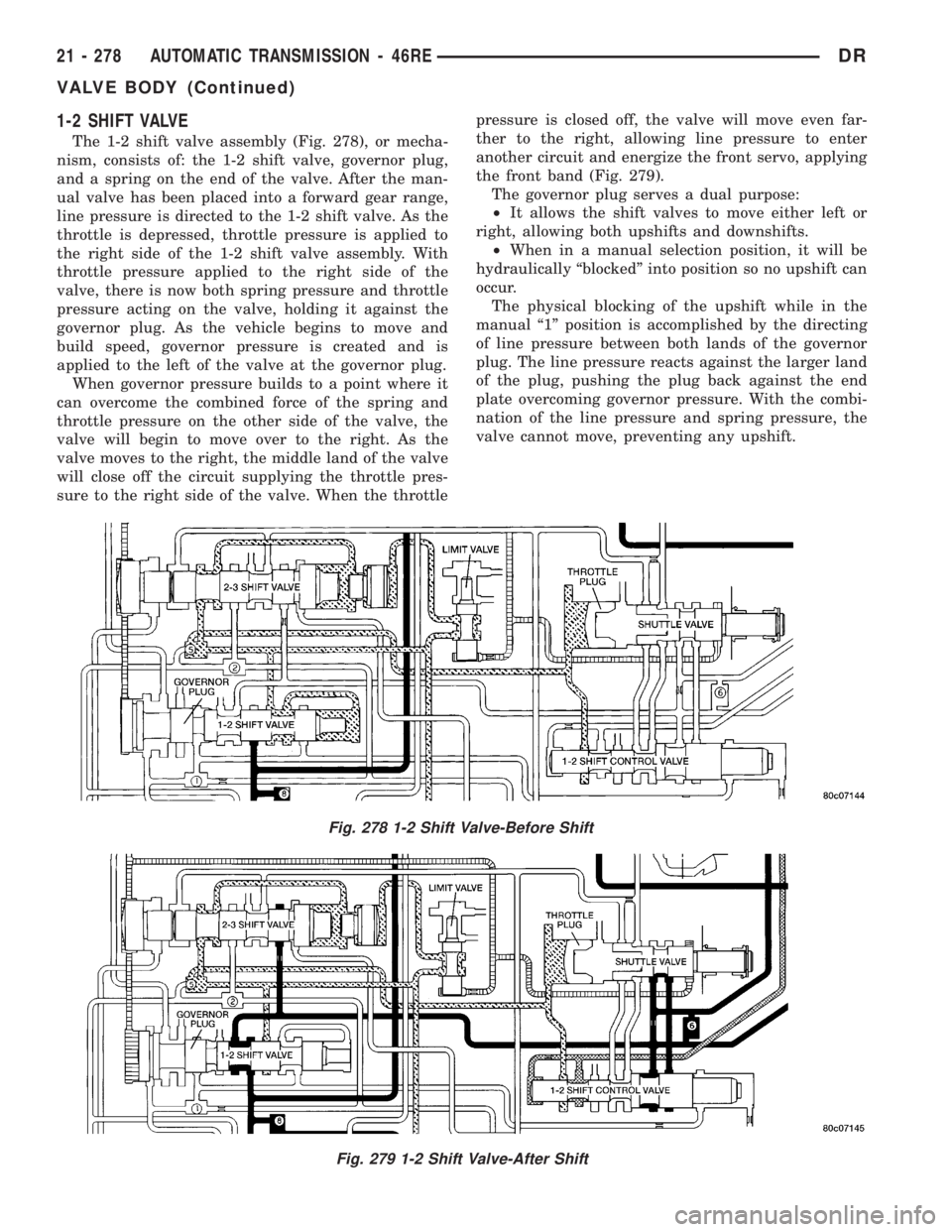
The 1-2 shift valve assembly (Fig. 278), or mecha-
nism, consists of: the 1-2 shift valve, governor plug,
and a spring on the end of the valve. After the man-
ual valve has been placed into a forward gear range,
line pressure is directed to the 1-2 shift valve. As the
throttle is depressed, throttle pressure is applied to
the right side of the 1-2 shift valve assembly. With
throttle pressure applied to the right side of the
valve, there is now both spring pressure and throttle
pressure acting on the valve, holding it against the
governor plug. As the vehicle begins to move and
build speed, governor pressure is created and is
applied to the left of the valve at the governor plug.
When governor pressure builds to a point where it
can overcome the combined force of the spring and
throttle pressure on the other side of the valve, the
valve will begin to move over to the right. As the
valve moves to the right, the middle land of the valve
will close off the circuit supplying the throttle pres-
sure to the right side of the valve. When the throttlepressure is closed off, the valve will move even far-
ther to the right, allowing line pressure to enter
another circuit and energize the front servo, applying
the front band (Fig. 279).
The governor plug serves a dual purpose:
²It allows the shift valves to move either left or
right, allowing both upshifts and downshifts.
²When in a manual selection position, it will be
hydraulically ªblockedº into position so no upshift can
occur.
The physical blocking of the upshift while in the
manual ª1º position is accomplished by the directing
of line pressure between both lands of the governor
plug. The line pressure reacts against the larger land
of the plug, pushing the plug back against the end
plate overcoming governor pressure. With the combi-
nation of the line pressure and spring pressure, the
valve cannot move, preventing any upshift.
Fig. 278 1-2 Shift Valve-Before Shift
Fig. 279 1-2 Shift Valve-After Shift
21 - 278 AUTOMATIC TRANSMISSION - 46REDR
VALVE BODY (Continued)
Page 2118 of 2895
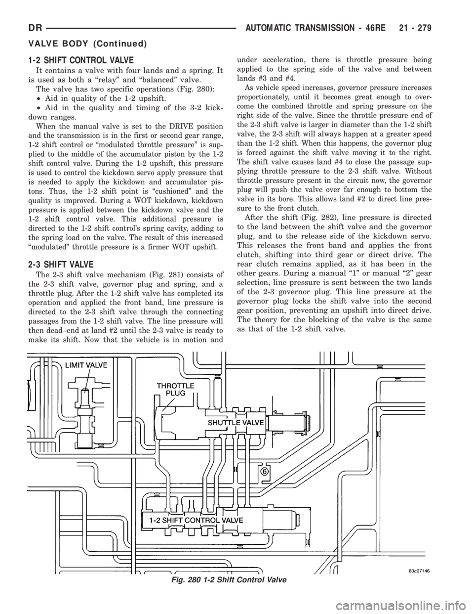
1-2 SHIFT CONTROL VALVE
It contains a valve with four lands and a spring. It
is used as both a ªrelayº and ªbalancedº valve.
The valve has two specific operations (Fig. 280):
²Aid in quality of the 1-2 upshift.
²Aid in the quality and timing of the 3-2 kick-
down ranges.
When the manual valve is set to the DRIVE position
and the transmission is in the first or second gear range,
1-2 shift control or ªmodulated throttle pressureº is sup-
plied to the middle of the accumulator piston by the 1-2
shift control valve. During the 1-2 upshift, this pressure
is used to control the kickdown servo apply pressure that
is needed to apply the kickdown and accumulator pis-
tons. Thus, the 1-2 shift point is ªcushionedº and the
quality is improved. During a WOT kickdown, kickdown
pressure is applied between the kickdown valve and the
1-2 shift control valve. This additional pressure is
directed to the 1-2 shift control's spring cavity, adding to
the spring load on the valve. The result of this increased
ªmodulatedº throttle pressure is a firmer WOT upshift.
2-3 SHIFT VALVE
The 2-3 shift valve mechanism (Fig. 281) consists of
the 2-3 shift valve, governor plug and spring, and a
throttle plug. After the 1-2 shift valve has completed its
operation and applied the front band, line pressure is
directed to the 2-3 shift valve through the connecting
passages from the 1-2 shift valve. The line pressure will
then dead±end at land #2 until the 2-3 valve is ready to
make its shift. Now that the vehicle is in motion andunder acceleration, there is throttle pressure being
applied to the spring side of the valve and between
lands #3 and #4.
As vehicle speed increases, governor pressure increases
proportionately, until it becomes great enough to over-
come the combined throttle and spring pressure on the
right side of the valve. Since the throttle pressure end of
the 2-3 shift valve is larger in diameter than the 1-2 shift
valve, the 2-3 shift will always happen at a greater speed
than the 1-2 shift. When this happens, the governor plug
is forced against the shift valve moving it to the right.
The shift valve causes land #4 to close the passage sup-
plying throttle pressure to the 2-3 shift valve. Without
throttle pressure present in the circuit now, the governor
plug will push the valve over far enough to bottom the
valve in its bore. This allows land #2 to direct line pres-
sure to the front clutch.
After the shift (Fig. 282), line pressure is directed
to the land between the shift valve and the governor
plug, and to the release side of the kickdown servo.
This releases the front band and applies the front
clutch, shifting into third gear or direct drive. The
rear clutch remains applied, as it has been in the
other gears. During a manual ª1º or manual ª2º gear
selection, line pressure is sent between the two lands
of the 2-3 governor plug. This line pressure at the
governor plug locks the shift valve into the second
gear position, preventing an upshift into direct drive.
The theory for the blocking of the valve is the same
as that of the 1-2 shift valve.
Fig. 280 1-2 Shift Control Valve
DRAUTOMATIC TRANSMISSION - 46RE 21 - 279
VALVE BODY (Continued)
Page 2157 of 2895
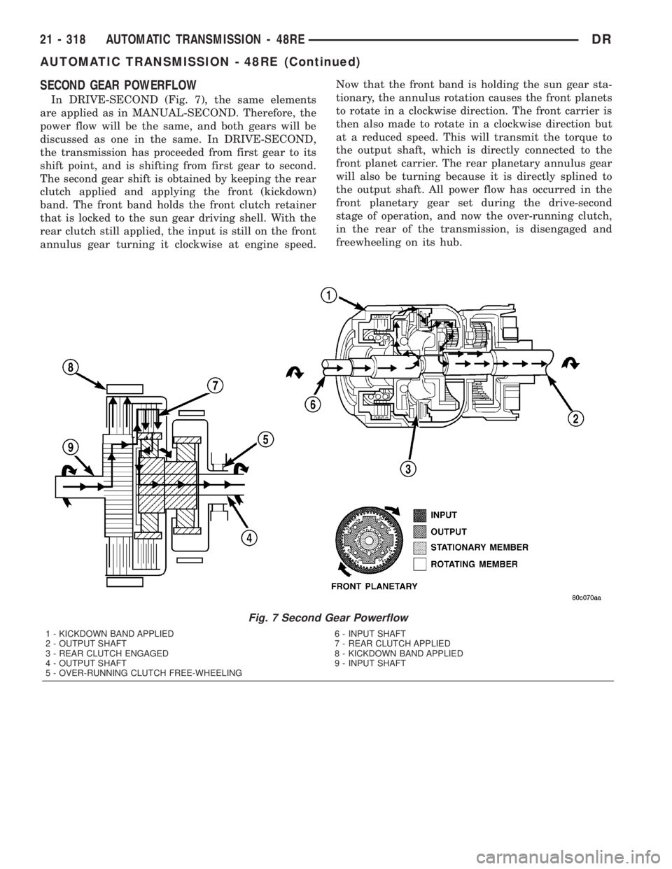
SECOND GEAR POWERFLOW
In DRIVE-SECOND (Fig. 7), the same elements
are applied as in MANUAL-SECOND. Therefore, the
power flow will be the same, and both gears will be
discussed as one in the same. In DRIVE-SECOND,
the transmission has proceeded from first gear to its
shift point, and is shifting from first gear to second.
The second gear shift is obtained by keeping the rear
clutch applied and applying the front (kickdown)
band. The front band holds the front clutch retainer
that is locked to the sun gear driving shell. With the
rear clutch still applied, the input is still on the front
annulus gear turning it clockwise at engine speed.Now that the front band is holding the sun gear sta-
tionary, the annulus rotation causes the front planets
to rotate in a clockwise direction. The front carrier is
then also made to rotate in a clockwise direction but
at a reduced speed. This will transmit the torque to
the output shaft, which is directly connected to the
front planet carrier. The rear planetary annulus gear
will also be turning because it is directly splined to
the output shaft. All power flow has occurred in the
front planetary gear set during the drive-second
stage of operation, and now the over-running clutch,
in the rear of the transmission, is disengaged and
freewheeling on its hub.
Fig. 7 Second Gear Powerflow
1 - KICKDOWN BAND APPLIED 6 - INPUT SHAFT
2 - OUTPUT SHAFT 7 - REAR CLUTCH APPLIED
3 - REAR CLUTCH ENGAGED 8 - KICKDOWN BAND APPLIED
4 - OUTPUT SHAFT 9 - INPUT SHAFT
5 - OVER-RUNNING CLUTCH FREE-WHEELING
21 - 318 AUTOMATIC TRANSMISSION - 48REDR
AUTOMATIC TRANSMISSION - 48RE (Continued)
Page 2269 of 2895
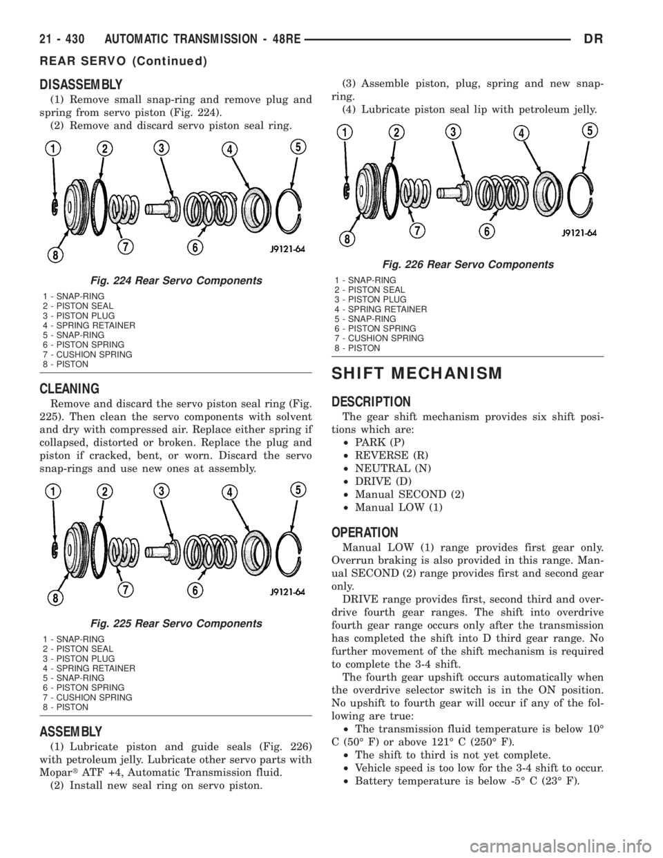
DISASSEMBLY
(1) Remove small snap-ring and remove plug and
spring from servo piston (Fig. 224).
(2) Remove and discard servo piston seal ring.
CLEANING
Remove and discard the servo piston seal ring (Fig.
225). Then clean the servo components with solvent
and dry with compressed air. Replace either spring if
collapsed, distorted or broken. Replace the plug and
piston if cracked, bent, or worn. Discard the servo
snap-rings and use new ones at assembly.
ASSEMBLY
(1) Lubricate piston and guide seals (Fig. 226)
with petroleum jelly. Lubricate other servo parts with
MopartATF +4, Automatic Transmission fluid.
(2) Install new seal ring on servo piston.(3) Assemble piston, plug, spring and new snap-
ring.
(4) Lubricate piston seal lip with petroleum jelly.
SHIFT MECHANISM
DESCRIPTION
The gear shift mechanism provides six shift posi-
tions which are:
²PARK (P)
²REVERSE (R)
²NEUTRAL (N)
²DRIVE (D)
²Manual SECOND (2)
²Manual LOW (1)
OPERATION
Manual LOW (1) range provides first gear only.
Overrun braking is also provided in this range. Man-
ual SECOND (2) range provides first and second gear
only.
DRIVE range provides first, second third and over-
drive fourth gear ranges. The shift into overdrive
fourth gear range occurs only after the transmission
has completed the shift into D third gear range. No
further movement of the shift mechanism is required
to complete the 3-4 shift.
The fourth gear upshift occurs automatically when
the overdrive selector switch is in the ON position.
No upshift to fourth gear will occur if any of the fol-
lowing are true:
²The transmission fluid temperature is below 10É
C (50É F) or above 121É C (250É F).
²The shift to third is not yet complete.
²Vehicle speed is too low for the 3-4 shift to occur.
²Battery temperature is below -5É C (23É F).
Fig. 224 Rear Servo Components
1 - SNAP-RING
2 - PISTON SEAL
3 - PISTON PLUG
4 - SPRING RETAINER
5 - SNAP-RING
6 - PISTON SPRING
7 - CUSHION SPRING
8 - PISTON
Fig. 225 Rear Servo Components
1 - SNAP-RING
2 - PISTON SEAL
3 - PISTON PLUG
4 - SPRING RETAINER
5 - SNAP-RING
6 - PISTON SPRING
7 - CUSHION SPRING
8 - PISTON
Fig. 226 Rear Servo Components
1 - SNAP-RING
2 - PISTON SEAL
3 - PISTON PLUG
4 - SPRING RETAINER
5 - SNAP-RING
6 - PISTON SPRING
7 - CUSHION SPRING
8 - PISTON
21 - 430 AUTOMATIC TRANSMISSION - 48REDR
REAR SERVO (Continued)
Page 2289 of 2895
OPERATION
NOTE: Refer to the Hydraulic Schematics for a
visual aid in determining valve location, operation
and design.
CHECK BALLS
CHECK BALL
NUMBERDESCRIPTION
1 Allows either the manual valve to put line pressure on the 1-2 governor plug or the KD Valve to
put WOT line pressure on the 1-2 governor plug.
3 Allows either the Reverse circuit or the 3rd gear circuit to pressurize the front clutch.
4 Allows either the Manual Low circuit from the Manual Valve or the Reverse from the Manual
Valve circuit to pressurize the rear servo.
5 Directs line pressure to the spring end of the 2-3 shift valve in either Manual Low or Manual
2nd, forcing the downshift to 2nd gear regardless of governor pressure.
6 Provides a by-pass around the front servo orifice so that the servo can release quickly.
7 Provides a by-pass around the rear clutch orifice so that the clutch can release quickly.
8 Directs reverse line pressure through an orifice to the throttle valve eliminating the extra
leakage and insuring that Reverse line pressure pressure will be sufficient.
9 Provides a by-pass around the rear servo orifice so that the servo can release quickly.
10 Allows the lockup clutch to used at WOT in 3rd gear by putting line pressure from the 3-4
Timing Valve on the interlock area of the 2-3 shift valve, thereby preventing a 3rd gear Lock-up
to 2nd gear kickdown.
REGULATOR VALVE
The pressure regulator valve is needed to control
the hydraulic pressure within the system and reduce
the amount of heat produced in the fluid. The pres-
sure regulator valve is located in the valve body near
the manual valve. The pressure regulator valve train
controls the maximum pressure in the lines by
metering the dumping of fluid back into the sump.
Regulated pressure is referred to as ªline pressure.º
The regulator valve (Fig. 255) has a spring on one
end that pushes the valve to the left. This closes a
dump (vent) that is used to lower pressure. The clos-
ing of the dump will cause the oil pressure to
increase. Oil pressure on the opposite end of the
valve pushes the valve to the right, opening the
dump and lowering oil pressure. The result is spring
pressure working against oil pressure to maintain
the oil at specific pressures. With the engine run-
ning, fluid flows from the pump to the pressure reg-
ulator valve, manual valve, and the interconnected
circuits. As fluid is sent through passages to the reg-
ulator valve, the pressure pushes the valve to the
right against the large spring. It is also sent to the
reaction areas on the left side of the throttle pressure
plug and the line pressure plug. With the gear selec-tor in the PARK position, fluid recirculates through
the regulator and manual valves back to the sump.
Meanwhile, the torque converter is filled slowly. In
all other gear positions (Fig. 256), fluid flows
between two right side lands to the switch valve and
torque converter. At low pump speeds, the flow is
controlled by the pressure valve groove to reduce
pressure to the torque converter. After the torque
converter and switch valve fill with fluid, the switch
valve becomes the controlling metering device for
torque converter pressure. The regulator valve then
begins to control the line pressure for the other
transmission circuits. The balance of the fluid pres-
sure pushing the valve to the right and the spring
pressure pushing to the left determines the size of
the metering passage at land #2 (land #1 being at
the far right of the valve in the diagram). As fluid
leaks past the land, it moves into a groove connected
to the filter or sump. As the land meters the fluid to
the sump, it causes the pressure to reduce and the
spring decreases the size of the metering passage.
When the size of the metering passage is reduced,
the pressure rises again and the size of the land is
increased again. Pressure is regulated by this con-
stant balance of hydraulic and spring pressure.
21 - 450 AUTOMATIC TRANSMISSION - 48REDR
VALVE BODY (Continued)