2003 DODGE RAM Valve body
[x] Cancel search: Valve bodyPage 247 of 2895

cuit separation in the event of a front or rear brake
malfunction. The reservoir compartments will retain
enough fluid to operate the functioning hydraulic cir-
cuit.
Care must be exercised when removing/installing
the master cylinder connecting lines. The threads in
the cylinder fluid ports can be damaged if care is not
exercised. Start all brake line fittings by hand to
avoid cross threading.
The cylinder reservoir can be replaced when neces-
sary. However, the aluminum body section of the
master cylinder is not a repairable component.
NOTE: If diagnosis indicates that an internal mal-
function has occurred, the aluminum body section
must be replaced as an assembly.
OPERATION
The master cylinder bore contains a primary and
secondary piston. The primary piston supplies
hydraulic pressure to the front brakes. The secondary
piston supplies hydraulic pressure to the rear brakes.
DIAGNOSIS AND TESTING - MASTER
CYLINDER/POWER BOOSTER
(1) Start engine and check booster vacuum hose
connections. A hissing noise indicates vacuum leak.
Correct any vacuum leak before proceeding.
(2) Stop engine and shift transmission into Neu-
tral.
(3) Pump brake pedal until all vacuum reserve in
booster is depleted.
(4) Press and hold brake pedal under light foot
pressure. The pedal should hold firm, if the pedal
falls away master cylinder is faulty (internal leak-
age).
(5) Start engine and note pedal action. It should
fall away slightly under light foot pressure then hold
firm. If no pedal action is discernible, power booster,
vacuum supply, or vacuum check valve is faulty. Pro-
ceed to the POWER BOOSTER VACUUM TEST.
(6) If the POWER BOOSTER VACUUM TEST
passes, rebuild booster vacuum reserve as follows:
Release brake pedal. Increase engine speed to 1500
rpm, close the throttle and immediately turn off igni-
tion to stop engine.
(7) Wait a minimum of 90 seconds and try brake
action again. Booster should provide two or more vac-
uum assisted pedal applications. If vacuum assist is
not provided, booster is faulty.
POWER BOOSTER VACUUM TEST
(1) Connect vacuum gauge to booster check valve
with short length of hose and T-fitting (Fig. 36).(2) Start and run engine at curb idle speed for one
minute.
(3) Observe the vacuum supply. If vacuum supply
is not adequate, repair vacuum supply.
(4) Clamp hose shut between vacuum source and
check valve.
(5) Stop engine and observe vacuum gauge.
(6) If vacuum drops more than one inch HG (33
millibars) within 15 seconds, booster diaphragm or
check valve is faulty.
POWER BOOSTER CHECK VALVE TEST
(1) Disconnect vacuum hose from check valve.
(2) Remove check valve and valve seal from
booster.
(3) Use a hand operated vacuum pump for test.
(4) Apply 15-20 inches vacuum at large end of
check valve (Fig. 37).
(5) Vacuum should hold steady. If gauge on pump
indicates vacuum loss, check valve is faulty and
should be replaced.
STANDARD PROCEDURE - MASTER CYLINDER
BLEEDING
A new master cylinder should be bled before instal-
lation on the vehicle. Required bleeding tools include
bleed tubes and a wood dowel to stroke the pistons.
Bleed tubes can be fabricated from brake line.
Fig. 36 Typical Booster Vacuum Test Connections
1 - TEE FITTING
2 - SHORT CONNECTING HOSE
3 - CHECK VALVE
4 - CHECK VALVE HOSE
5 - CLAMP TOOL
6 - INTAKE MANIFOLD
7 - VACUUM GAUGE
5 - 20 BRAKES - BASEDR
MASTER CYLINDER (Continued)
Page 252 of 2895
(2) Install the one mounting bolt for the adjustable
pedal motor (Fig. 46).
(3) Clip the cable fasteners to the support.
(4) Reconnect the electrical connector.
(5) Reconnect the adjustable pedal cables to the
brake and accelerator pedals.
(6) Install the new brake light switch (Refer to 8 -
ELECTRICAL/LAMPS/LIGHTING - EXTERIOR/
BRAKE LAMP SWITCH - REMOVAL).
(7) Install the kneeblocker (Refer to 23 - BODY/IN-
STRUMENT PANEL/STEERING COLUMN OPEN-
ING COVER - INSTALLATION).
(8) Reconnect the negative battery cable.
(9) Check for proper operation of the pedals.
POWER BRAKE BOOSTER
DESCRIPTION
All models use a tandem diaphragm, power brake
booster.
NOTE: The power brake booster is not a repairable
component. The booster must be replaced as an
assembly if diagnosis indicates a malfunction has
occurred.
OPERATION
The booster unit consists of a single housing
divided into two by a tandem diaphragm. The outer
edge of the diaphragm is secured to the housing. The
booster push rod, which connects the booster to the
brake pedal and master cylinder, is attached to the
center of the diaphragm. A check valve is used in the
booster outlet connected to the engine intake mani-
fold. Power assist is generated by utilizing a combi-
nation of vacuum and atmospheric pressure to boost
brake assist.
REMOVAL
(1) Remove master cylinder. (Refer to 5 - BRAKES/
HYDRAULIC/MECHANICAL/MASTER CYLINDER -
REMOVAL).
(2) Disconnect vacuum line at booster.
(3) Remove clip securing booster push rod to brake
pedal (Refer to 5 - BRAKES/HYDRAULIC/MECHAN-
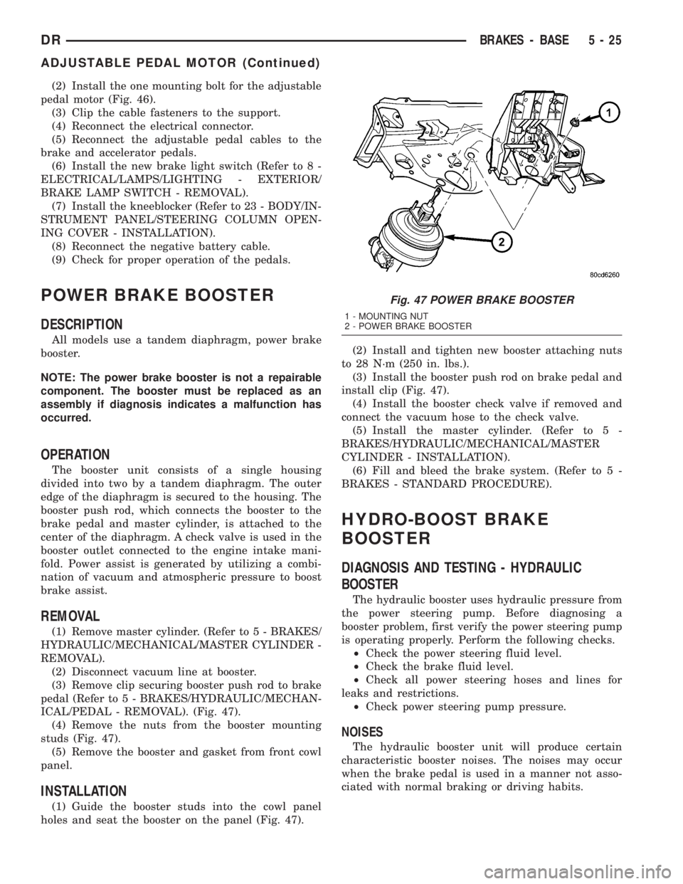
ICAL/PEDAL - REMOVAL). (Fig. 47).
(4) Remove the nuts from the booster mounting
studs (Fig. 47).
(5) Remove the booster and gasket from front cowl
panel.
INSTALLATION
(1) Guide the booster studs into the cowl panel
holes and seat the booster on the panel (Fig. 47).(2) Install and tighten new booster attaching nuts
to 28 N´m (250 in. lbs.).
(3) Install the booster push rod on brake pedal and
install clip (Fig. 47).
(4) Install the booster check valve if removed and
connect the vacuum hose to the check valve.
(5) Install the master cylinder. (Refer to 5 -
BRAKES/HYDRAULIC/MECHANICAL/MASTER
CYLINDER - INSTALLATION).
(6) Fill and bleed the brake system. (Refer to 5 -
BRAKES - STANDARD PROCEDURE).
HYDRO-BOOST BRAKE
BOOSTER
DIAGNOSIS AND TESTING - HYDRAULIC
BOOSTER
The hydraulic booster uses hydraulic pressure from
the power steering pump. Before diagnosing a
booster problem, first verify the power steering pump
is operating properly. Perform the following checks.
²Check the power steering fluid level.
²Check the brake fluid level.
²Check all power steering hoses and lines for
leaks and restrictions.
²Check power steering pump pressure.
NOISES
The hydraulic booster unit will produce certain
characteristic booster noises. The noises may occur
when the brake pedal is used in a manner not asso-
ciated with normal braking or driving habits.
Fig. 47 POWER BRAKE BOOSTER
1 - MOUNTING NUT
2 - POWER BRAKE BOOSTER
DRBRAKES - BASE 5 - 25
ADJUSTABLE PEDAL MOTOR (Continued)
Page 267 of 2895

The purpose of the antilock system is to prevent
wheel lockup. Preventing lockup helps maintain vehi-
cle braking action and steering control.
The antilock CAB activates the system whenever
sensor signals indicate periods of wheel slip.
The antilock system prevents lockup during a
wheel slip condition by modulating fluid apply pres-
sure to the wheel brake units.
Brake fluid apply pressure is modulated according
to wheel speed, degree of slip and rate of decelera-
tion. Sensors at each front wheel convert wheel speed
into electrical signals. These signals are transmitted
to the CAB for processing and determination of
wheel slip and deceleration rate.
The ABS system has three fluid pressure control
channels. The front brakes are controlled separately
and the rear brakes in tandem. A speed sensor input
signal indicating a wheel slip condition activates the
CAB antilock program.
There are Two solenoid valves (Isolation and Dump
valve) which are used in each antilock control chan-
nel. The valves are all located within the HCU valve
body and work in pairs to either increase, hold, or
decrease apply pressure as needed in the individual
control channels.
During an ABS stop the ISO valve is energized
which acts to prevent further pressure build-up tothe calipers. Then the Dump valve dumps off pres-
sure until the wheel unlocks. This will continue until
the wheels quit slipping altogether.
STANDARD PROCEDURE - ABS BRAKE
BLEEDING
ABS system bleeding requires conventional bleed-
ing methods plus use of the DRB scan tool. The pro-
cedure involves performing a base brake bleeding,
followed by use of the scan tool to cycle and bleed the
HCU pump and solenoids. A second base brake bleed-
ing procedure is then required to remove any air
remaining in the system.
(1) Perform base brake bleeding,(Refer to 5 -
BRAKES - STANDARD PROCEDURE) OR (Refer to
5 - BRAKES - STANDARD PROCEDURE).
(2) Connect scan tool to the Data Link Connector.
(3) Select ANTILOCK BRAKES, followed by MIS-
CELLANEOUS, then ABS BRAKES. Follow the
instructions displayed. When scan tool displays TEST
COMPLETE, disconnect scan tool and proceed.
(4) Perform base brake bleeding a second time,(Re-
fer to 5 - BRAKES - STANDARD PROCEDURE) OR
(Refer to 5 - BRAKES - STANDARD PROCEDURE).
(5) Top off master cylinder fluid level and verify
proper brake operation before moving vehicle.
SPECIFICATIONS
TORQUE CHART
TORQUE SPECIFICATIONS
DESCRIPTION N´m Ft. Lbs. In. Lbs.
ABS Assembly
Mounting Bolts15 11 Ð
ABS Assembly
CAB Screws3.5 Ð 31
ABS Assembly
Brake Line Fittings19 Ð 170
Wheel Speed Sensors
Front Sensor Bolt21 Ð 190
Wheel Speed Sensors
Bracket To Knuckle6.7 Ð 60
Wheel Speed Sensors
Rear Sensor Stud22.5 Ð 200
Controller
Mounting Screws6Ð53
RWAL Module
Mounting Bolts15 11 Ð
5 - 40 BRAKES - ABSDR
BRAKES - ABS (Continued)
Page 270 of 2895

INSTALLATION
(1) Connect the harness to the sensor.Be sure
the seal is securely in place between the sensor
and the wiring connector.
(2) Install the O-ring on the sensor (if removed).
(3) Insert the sensor in the differential housing.
(4) Install the sensor shield.
(5) Install the sensor mounting stud and tighten to
24 N´m (200 in. lbs.).
(6) Install the brake line on the sensor stud and
install the nut.
(7) Lower the vehicle.
TONE WHEEL
DIAGNOSIS AND TESTING - REAR WHEEL
SPEED SENSOR
Diagnosis of base brake conditions which are
mechanical in nature should be performed first. This
includes brake noise, lack of power assist, parking
brake, or vehicle vibration during normal braking.
The Antilock brake system performs several self-
tests every time the ignition switch is turned on and
the vehicle is driven. The CAB monitors the system
inputs and outputs circuits to verify the system is
operating properly. If the CAB senses a malfunction
in the system it will set a DTC into memory and trig-
ger the warning lamp.
NOTE: The MDS or DRB III scan tool is used to
diagnose the Antilock Brake system. For test proce-
dures refer to the Chassis Diagnostic Manual.
HYDRAULIC/MECHANICAL
DESCRIPTION - ELECTRONIC VARIABLE
BRAKE PROPORTIONING
Vehicles equipped with ABS use electronic variable
brake proportioning (EVBP) to balance front-to-rear
braking. The EVBP is used in place of a rear propor-
tioning valve. The EVBP system uses the ABS sys-
tem to control the slip of the rear wheels in partial
braking range. The braking force of the rear wheels
is controlled electronically by using the inlet and out-
let valves located in the integrated control unit
(ICU).
OPERATION - ELECTRONIC VARIABLE BRAKE
PROPORTIONING
EVBP is able to decrease, hold and increase rear
brake pressure without activating full ABS control.
Upon entry into EVBP the inlet valve for the rear
brake circuit is switched on so that the fluid supplyfrom the master cylinder is shut off. In order to
decrease the rear brake pressure, the outlet valve for
the rear brake circuit is pulsed. This allows fluid to
enter the low pressure accumulator (LPA) in the
hydraulic control unit (HCU) resulting in a drop in
fluid pressure to the rear brakes. In order to increase
the rear brake pressure, the outlet valve is switched
off and the inlet valve is pulsed. This increases the
pressure to the rear brakes.
The EVBP will remain functional during many
ABS fault modes. If both the red BRAKE and amber
ABS warning indicators are illuminated, the EVBP
may not be functioning.
HCU (HYDRAULIC CONTROL
UNIT)
DESCRIPTION
The HCU consists of a valve body, pump motor, low
pressure accumulators, inlet valves, outlet valves and
noise attenuators.
OPERATION
Accumulators in the valve body store extra fluid
released to the system for ABS mode operation. The
pump provides the fluid volume needed and is oper-
ated by a DC type motor. The motor is controlled by
the CAB.
The valves modulate brake pressure during
antilock braking and are controlled by the CAB.
The HCU provides three channel pressure control
to the front and rear brakes. One channel controls
the rear wheel brakes in tandem. The two remaining
channels control the front wheel brakes individually.
During antilock braking, the solenoid valves are
opened and closed as needed.
During normal braking, the HCU solenoid valves
and pump are not activated. The master cylinder and
power booster operate the same as a vehicle without
an ABS brake system.
NOTE: The three modes mentioned below do occur
but not necessarily in the order listed everytime.
During antilock braking, solenoid valve pressure
modulation occurs in three stages, pressure increase,
pressure hold, and pressure decrease. The valves are
all contained in the valve body portion of the HCU.
PRESSURE DECREASE
The outlet valve is opened and the inlet valve is
closed during the pressure decrease cycle.
A pressure decrease cycle is initiated when speed
sensor signals indicate high wheel slip at one or
more wheels. At this point, the CAB closes the inlet
DRBRAKES - ABS 5 - 43
REAR WHEEL SPEED SENSOR (Continued)
Page 349 of 2895
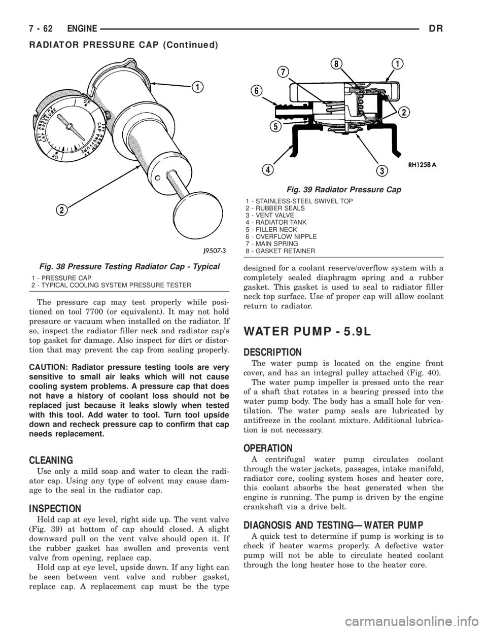
The pressure cap may test properly while posi-
tioned on tool 7700 (or equivalent). It may not hold
pressure or vacuum when installed on the radiator. If
so, inspect the radiator filler neck and radiator cap's
top gasket for damage. Also inspect for dirt or distor-
tion that may prevent the cap from sealing properly.
CAUTION: Radiator pressure testing tools are very
sensitive to small air leaks which will not cause
cooling system problems. A pressure cap that does
not have a history of coolant loss should not be
replaced just because it leaks slowly when tested
with this tool. Add water to tool. Turn tool upside
down and recheck pressure cap to confirm that cap
needs replacement.
CLEANING
Use only a mild soap and water to clean the radi-
ator cap. Using any type of solvent may cause dam-
age to the seal in the radiator cap.
INSPECTION
Hold cap at eye level, right side up. The vent valve
(Fig. 39) at bottom of cap should closed. A slight
downward pull on the vent valve should open it. If
the rubber gasket has swollen and prevents vent
valve from opening, replace cap.
Hold cap at eye level, upside down. If any light can
be seen between vent valve and rubber gasket,
replace cap. A replacement cap must be the typedesigned for a coolant reserve/overflow system with a
completely sealed diaphragm spring and a rubber
gasket. This gasket is used to seal to radiator filler
neck top surface. Use of proper cap will allow coolant
return to radiator.
WATER PUMP - 5.9L
DESCRIPTION
The water pump is located on the engine front
cover, and has an integral pulley attached (Fig. 40).
The water pump impeller is pressed onto the rear
of a shaft that rotates in a bearing pressed into the
water pump body. The body has a small hole for ven-
tilation. The water pump seals are lubricated by
antifreeze in the coolant mixture. Additional lubrica-
tion is not necessary.
OPERATION
A centrifugal water pump circulates coolant
through the water jackets, passages, intake manifold,
radiator core, cooling system hoses and heater core,
this coolant absorbs the heat generated when the
engine is running. The pump is driven by the engine
crankshaft via a drive belt.
DIAGNOSIS AND TESTINGÐWATER PUMP
A quick test to determine if pump is working is to
check if heater warms properly. A defective water
pump will not be able to circulate heated coolant
through the long heater hose to the heater core.
Fig. 38 Pressure Testing Radiator Cap - Typical
1 - PRESSURE CAP
2 - TYPICAL COOLING SYSTEM PRESSURE TESTER
Fig. 39 Radiator Pressure Cap
1 - STAINLESS-STEEL SWIVEL TOP
2 - RUBBER SEALS
3 - VENT VALVE
4 - RADIATOR TANK
5 - FILLER NECK
6 - OVERFLOW NIPPLE
7 - MAIN SPRING
8 - GASKET RETAINER
7 - 62 ENGINEDR
RADIATOR PRESSURE CAP (Continued)
Page 402 of 2895
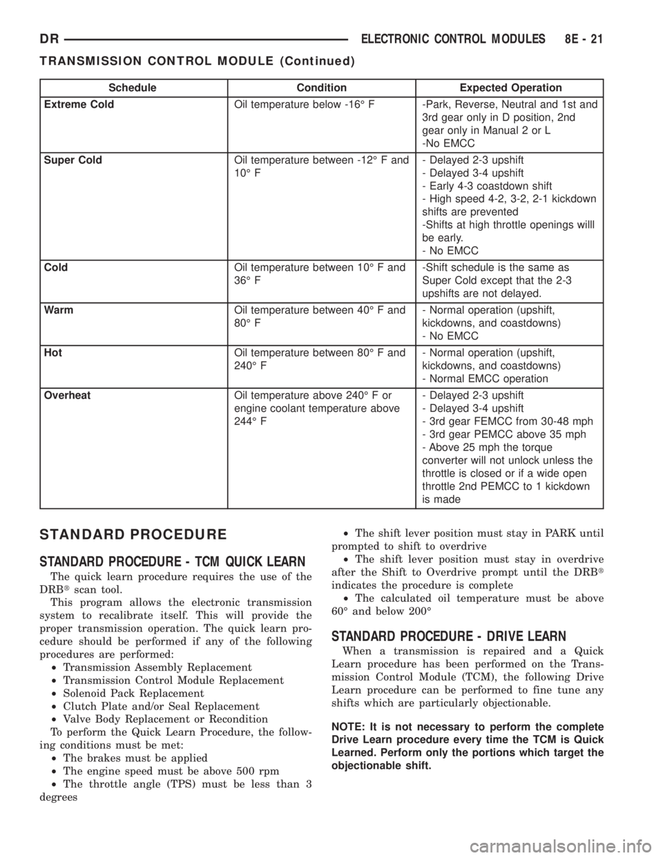
Schedule Condition Expected Operation
Extreme ColdOil temperature below -16É F -Park, Reverse, Neutral and 1st and
3rd gear only in D position, 2nd
gear only in Manual 2 or L
-No EMCC
Super ColdOil temperature between -12É F and
10É F- Delayed 2-3 upshift
- Delayed 3-4 upshift
- Early 4-3 coastdown shift
- High speed 4-2, 3-2, 2-1 kickdown
shifts are prevented
-Shifts at high throttle openings willl
be early.
- No EMCC
ColdOil temperature between 10É F and
36É F-Shift schedule is the same as
Super Cold except that the 2-3
upshifts are not delayed.
WarmOil temperature between 40É F and
80É F- Normal operation (upshift,
kickdowns, and coastdowns)
- No EMCC
HotOil temperature between 80É F and
240É F- Normal operation (upshift,
kickdowns, and coastdowns)
- Normal EMCC operation
OverheatOil temperature above 240É F or
engine coolant temperature above
244É F- Delayed 2-3 upshift
- Delayed 3-4 upshift
- 3rd gear FEMCC from 30-48 mph
- 3rd gear PEMCC above 35 mph
- Above 25 mph the torque
converter will not unlock unless the
throttle is closed or if a wide open
throttle 2nd PEMCC to 1 kickdown
is made
STANDARD PROCEDURE
STANDARD PROCEDURE - TCM QUICK LEARN
The quick learn procedure requires the use of the
DRBtscan tool.
This program allows the electronic transmission
system to recalibrate itself. This will provide the
proper transmission operation. The quick learn pro-
cedure should be performed if any of the following
procedures are performed:
²Transmission Assembly Replacement
²Transmission Control Module Replacement
²Solenoid Pack Replacement
²Clutch Plate and/or Seal Replacement
²Valve Body Replacement or Recondition
To perform the Quick Learn Procedure, the follow-
ing conditions must be met:
²The brakes must be applied
²The engine speed must be above 500 rpm
²The throttle angle (TPS) must be less than 3
degrees²The shift lever position must stay in PARK until
prompted to shift to overdrive
²The shift lever position must stay in overdrive
after the Shift to Overdrive prompt until the DRBt
indicates the procedure is complete
²The calculated oil temperature must be above
60É and below 200É
STANDARD PROCEDURE - DRIVE LEARN
When a transmission is repaired and a Quick
Learn procedure has been performed on the Trans-
mission Control Module (TCM), the following Drive
Learn procedure can be performed to fine tune any
shifts which are particularly objectionable.
NOTE: It is not necessary to perform the complete
Drive Learn procedure every time the TCM is Quick
Learned. Perform only the portions which target the
objectionable shift.
DRELECTRONIC CONTROL MODULES 8E - 21
TRANSMISSION CONTROL MODULE (Continued)
Page 480 of 2895

The PCM adjusts ignition timing based on inputs it
receives from:
²The engine coolant temperature sensor
²The crankshaft position sensor (engine speed)
²The camshaft position sensor (crankshaft posi-
tion)
²The manifold absolute pressure (MAP) sensor
²The throttle position sensor
²Transmission gear selection
REMOVAL
3.7L V-6
An individual ignition coil is used for each spark
plug (Fig. 30). The coil fits into machined holes in the
cylinder head. A mounting stud/nut secures each coil
to the top of the intake manifold (Fig. 31). The bot-
tom of the coil is equipped with a rubber boot to seal
the spark plug to the coil. Inside each rubber boot is
a spring. The spring is used for a mechanical contact
between the coil and the top of the spark plug. These
rubber boots and springs are a permanent part of the
coil and are not serviced separately. An o-ring (Fig.
30) is used to seal the coil at the opening into the cyl-
inder head.
(1) Depending on which coil is being removed, the
throttle body air intake tube or intake box may need
to be removed to gain access to coil.
(2) Disconnect electrical connector from coil by
pushing downward on release lock on top of connec-
tor and pull connector from coil.
(3) Clean area at base of coil with compressed air
before removal.
(4) Remove coil mounting nut from mounting stud
(Fig. 31).
(5) Carefully pull up coil from cylinder head open-
ing with a slight twisting action.
(6) Remove coil from vehicle.
4.7L V-8
An individual ignition coil is used for each spark
plug (Fig. 30). The coil fits into machined holes in the
cylinder head. A mounting stud/nut secures each coil
to the top of the intake manifold (Fig. 32). The bot-
tom of the coil is equipped with a rubber boot to seal
the spark plug to the coil. Inside each rubber boot is
a spring. The spring is used for a mechanical contact
between the coil and the top of the spark plug. These
rubber boots and springs are a permanent part of the
coil and are not serviced separately. An o-ring (Fig.
30) is used to seal the coil at the opening into the cyl-
inder head.
(1) Depending on which coil is being removed, the
throttle body air intake tube or intake box may need
to be removed to gain access to coil.(2) Disconnect electrical connector (Fig. 32) from
coil by pushing downward on release lock on top of
connector and pull connector from coil.
(3) Clean area at base of coil with compressed air
before removal.
(4) Remove coil mounting nut from mounting stud
(Fig. 32).
(5) Carefully pull up coil from cylinder head open-
ing with a slight twisting action.
(6) Remove coil from vehicle.
5.7L V-8
Before removing or disconnecting any spark plug
cables, note their original position. Remove cables
one-at-a-time. To prevent ignition crossfire, spark
plug cablesMUSTbe placed in cable tray (routing
loom) into their original position.
An individual ignition coil (Fig. 33) is used at each
cylinder. The coil mounts to the top of the valve cover
with 2 bolts (Fig. 34). The bottom of the coil is
equipped with a rubber boot to seal the spark plug to
the coil. Inside each rubber boot is a spring. The
spring is used for a mechanical contact between the
coil and the top of the spark plug.
(1) Depending on which coil is being removed, the
throttle body air intake tube or intake box may need
to be removed to gain access to coil.
(2) Unlock electrical connector (Fig. 34) by moving
slide lock first. Press on release lock (Fig. 34) while
pulling electrical connector from coil.
(3) Disconnect secondary high-voltage cable from
coil with a twisting action.
(4) Clean area at base of coil with compressed air
before removal.
(5) Remove 2 mounting bolts (note that mounting
bolts are retained to coil).
(6) Carefully pull up coil from cylinder head open-
ing with a slight twisting action.
(7) Remove coil from vehicle.
(8) Before installing spark plug cables to either the
spark plugs or coils, or before installing a coil to a
spark plug, apply dielectric grease to inside of boots.
5.9L V-8
The coil is not oil filled. The coil windings are
embedded in an epoxy compound. This provides heat
and vibration resistance that allows the coil to be
mounted on the engine. If the coil is replaced, it must
be replaced with the same type.
5.9L V-8 LDC-Gas Engines: The coil is mounted to
a bracket that is bolted to the front of the right
engine cylinder head (Fig. 35). This bracket is
mounted on top of the automatic belt tensioner
bracket using common bolts.
DRIGNITION CONTROL 8I - 23
IGNITION COIL (Continued)
Page 481 of 2895

WARNING: 5.9L V-8 LDC-GAS ENGINES: DO NOT
REMOVE THE COIL MOUNTING BRACKET-TO-CYL-
INDER HEAD MOUNTING BOLTS. THE COIL
MOUNTING BRACKET IS UNDER ACCESSORY
DRIVE BELT TENSION. IF THIS BRACKET IS TO BE
REMOVED FOR ANY REASON, ALL BELT TENSION
MUST FIRST BE RELIEVED. REFER TO THE BELT
SECTION OF GROUP 7, COOLING SYSTEM.
5.9L V-8 HDC-Gas Engine: The coil is mounted to
a bracket that is bolted to the air injection pump
(AIR pump) mounting bracket (Fig. 36).
(1) Disconnect primary coil connector from ignition
coil.
(2) Disconnect secondary cable from ignition coil.
(3) Remove ignition coil from coil mounting
bracket (two bolts).
8.0L V-10
Two separate coil packs containing a total of five
independent coils are attached to a common mount-
ing bracket located above the right engine valve
cover (Fig. 37). The front and rear coil packs can be
serviced separately.
(1) Depending on which coil is being removed, the
throttle body air intake tube or intake box may need
to be removed to gain access to coils.
(2) Remove secondary spark plug cables from coil
packs. Note position of cables before removal.
(3) Disconnect primary wiring harness connectors
at coil packs.
(4) Remove four (4) coil pack-to-coil mounting
bracket bolts for coil pack being serviced (Fig. 37).
(5) Remove coil(s) from mounting bracket.
INSTALLATION
3.7L V-6
(1) Using compressed air, blow out any dirt or con-
taminants from around top of spark plug.
(2) Check condition of coil o-ring and replace as
necessary. To aid in coil installation, apply silicone to
coil o-ring.
(3) Position ignition coil into cylinder head opening
and push onto spark plug. Do this while guiding coil
base over mounting stud.
(4) Install coil mounting stud nut. Refer to torque
specifications.
(5) Connect electrical connector to coil by snapping
into position.
(6) If necessary, install throttle body air tube.
4.7L V-8
(1) Using compressed air, blow out any dirt or con-
taminants from around top of spark plug.
(2) Check condition of coil o-ring and replace as
necessary. To aid in coil installation, apply silicone to
coil o-ring.
(3) Position ignition coil into cylinder head opening
and push onto spark plug. Do this while guiding coil
base over mounting stud.
(4) Install coil mounting stud nut. Refer to torque
specifications.
(5) Connect electrical connector to coil by snapping
into position.
(6) If necessary, install throttle body air tube.
5.7L V-8
(1) Using compressed air, blow out any dirt or con-
taminants from around top of spark plug.
(2) Before installing spark plug cables to either the
spark plugs or coils, or before installing a coil to a
spark plug, apply dielectric grease to inside of boots.
(3) Position ignition coil into cylinder head opening
and push onto spark plug. Twist coil into position.
(4) Install 2 coil mounting bolts. Refer to torque
specifications.
(5) Connect electrical connector to coil by snapping
into position.
(6) Install cable to coil. To prevent ignition cross-
fire, spark plug cablesMUSTbe placed in cable tray
(routing loom) into their original position. Refer to
Spark Plug Cable Removal for a graphic.
(7) If necessary, install throttle body air tube.
5.9L V-8
The ignition coil is an epoxy filled type. If the coil
is replaced, it must be replaced with the same type.
(1) Install ignition coil to coil bracket. If nuts and
bolts are used to secure coil to coil bracket, tighten to
11 N´m (100 in. lbs.) torque. If coil mounting bracket
has been tapped for coil mounting bolts, tighten bolts
to 5 N´m (50 in. lbs.) torque.
(2) Connect all wiring to ignition coil.
8.0L V-10
(1) Position coil packs to mounting bracket (prima-
ry wiring connectors face downward).
(2) Install coil pack mounting bolts. Tighten bolts
to 10 N´m (90 in. lbs.) torque.
(3) Install coil pack-to-engine mounting bracket (if
necessary).
(4) Connect primary wiring connectors to coil
packs (four wire connector to front coil pack and
three wire connector to rear coil pack).
(5) Connect secondary spark plug cables to coil
packs. Refer to (Fig. 38) for correct cable order.
8I - 24 IGNITION CONTROLDR
IGNITION COIL (Continued)