2003 DODGE RAM shifter
[x] Cancel search: shifterPage 1802 of 2895
INSTALLATION
WARNING: BEFORE SERVICING THE STEERING
COLUMN THE AIRBAG SYSTEM MUST BE DIS-
ARMED. REFER TO ELECTRICAL RESTRAINT SYS-
TEM FOR SERVICE PROCEDURES. FAILURE TO DO
SO MAY RESULT IN ACCIDENTAL DEPLOYMENT OF
THE AIRBAG AND POSSIBLE PERSONAL INJURY.
CAUTION: All fasteners must be torqued to specifi-
cation to ensure proper operation of the steering
column.
(1) Position the steering column on the dash panel
support and loosely install the mounting nuts.
(2) Firmly slide the steering column upward
against the studs in dash panel and hand tighten the
nuts.
(3) Install the steering shaft coupler on the steer-
ing shaft and loosely install anewbolt.
(4) Center steering column in dash opening and
tighten mounting nuts to 28 N´m (250 in. lbs.).
NOTE: Torque the upper left nut first then the lower
right nut. Then torque the lower left nut then the
upper right nut.
NOTE: A new bolt must be used for reinstallation.
(5) Tighten the coupler bolt to 57 N´m (42 ft. lbs.).
(6) Install a new brake light switch (Refer to 8 -
ELECTRICAL/LAMPS/LIGHTING - EXTERIOR/
BRAKE LAMP SWITCH - REMOVAL).(7) Install the shifter cable. (Refer to 21 - TRANS-
MISSION/TRANSAXLE/AUTOMATIC - 32RH/GEAR
SHIFT CABLE - INSTALLATION)
(8) Connect the wiring harness to the column.
(9) Install the SKIM module.
(10) Install the clockspring(Refer to 8 - ELECTRI-
CAL/RESTRAINTS/CLOCKSPRING - REMOVAL).
(11) Install the shrouds.
(12) Install the steering column opening cover
(Refer to 23 - BODY/INSTRUMENT PANEL/STEER-
ING COLUMN OPENING COVER - INSTALLA-
TION).
(13) Align the spline on the wheel hub to shaft.
(14) Then install the steering wheel and install a
newbolt. Tighten the bolt to 61 N´m (45 ft. lbs.).
(15) Install the airbag (Refer to 8 - ELECTRICAL/
RESTRAINTS/DRIVER AIRBAG - INSTALLATION).
(16) Install the two steering wheel switches.
(17) Install the tilt lever handle.
(18) Install the negative battery terminal.
(19) Test the operation of the horn, Electronic
PRNDL Indicator, lights and any other functions that
are steering column operated.IGNITION SWITCH
DESCRIPTION
The ignition switch is located on the steering col-
umn. It is used as the main on/off switching device
for most electrical components. The mechanical key
cylinder is used to engage/disengage the electrical
ignition switch.
OPERATION
Vehicles equipped with an automatic trans-
mission and a steering column mounted shifter:
an interlock device is located within the shift cable.
This interlock device is used to lock the transmission
shifter in the PARK position when the key cylinder is
in any position and the brake pedal is not depressed.
DIAGNOSIS AND TESTING - IGNITION SWITCH
TEST AND REPAIR
If the key removal effort is excessive on a vehicle
with a automatic transmission first adjust the shift
linkage, (Refer to 21 - TRANSMISSION/TRANS-
AXLE/AUTOMATIC - 46RE/GEAR SHIFT CABLE -
ADJUSTMENTS).
If the ignition switch effort is excessive remove the
ignition key cylinder from the steering column. (Refer
to 19 - STEERING/COLUMN/LOCK CYLINDER
HOUSING - REMOVAL). Check the turning effort of
the key cylinder. If the ignition key cylinder effort is
excessive replace the key cylinder.
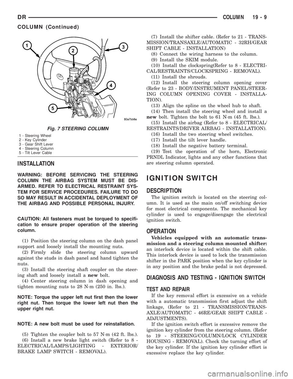
Fig. 7 STEERING COLUMN
1 - Steering Wheel
2 - Key Cylinder
3 - Gear Shift Lever
4 - Steering Column
5 - Tilt Lever Cable
DRCOLUMN 19 - 9
COLUMN (Continued)
Page 1805 of 2895
KEY CYLINDER
REMOVAL
The ignition key must be in the key cylinder for
cylinder removal.
(1) Disconnect negative cable from battery.
(2) Remove upper and lower covers (shrouds) from
steering column.
(3) Place shifter in PARK position.
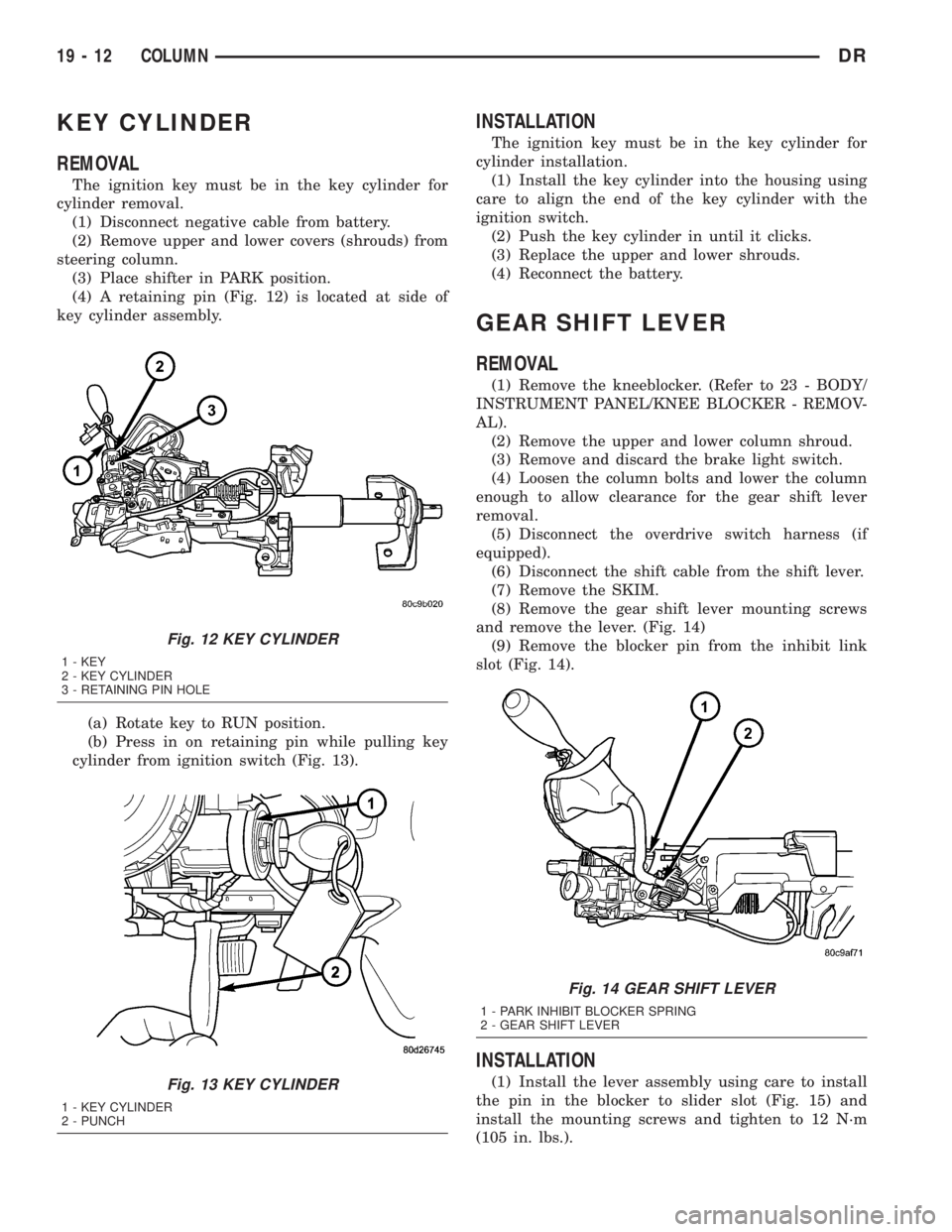
(4) A retaining pin (Fig. 12) is located at side of
key cylinder assembly.
(a) Rotate key to RUN position.
(b) Press in on retaining pin while pulling key
cylinder from ignition switch (Fig. 13).
INSTALLATION
The ignition key must be in the key cylinder for
cylinder installation.
(1) Install the key cylinder into the housing using
care to align the end of the key cylinder with the
ignition switch.
(2) Push the key cylinder in until it clicks.
(3) Replace the upper and lower shrouds.
(4) Reconnect the battery.
GEAR SHIFT LEVER
REMOVAL
(1) Remove the kneeblocker. (Refer to 23 - BODY/
INSTRUMENT PANEL/KNEE BLOCKER - REMOV-
AL).
(2) Remove the upper and lower column shroud.
(3) Remove and discard the brake light switch.
(4) Loosen the column bolts and lower the column
enough to allow clearance for the gear shift lever
removal.
(5) Disconnect the overdrive switch harness (if
equipped).
(6) Disconnect the shift cable from the shift lever.
(7) Remove the SKIM.
(8) Remove the gear shift lever mounting screws
and remove the lever. (Fig. 14)
(9) Remove the blocker pin from the inhibit link
slot (Fig. 14).
INSTALLATION
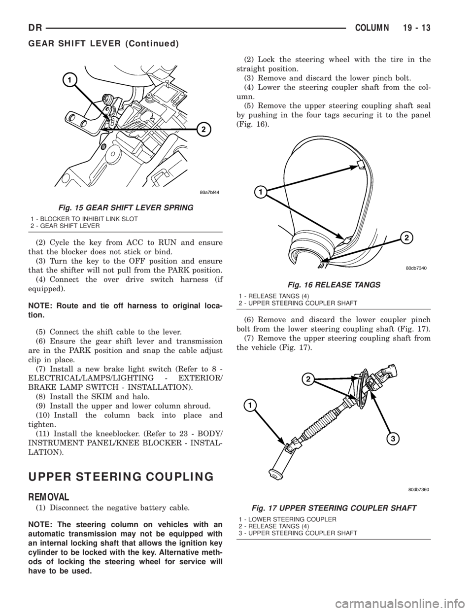
(1) Install the lever assembly using care to install
the pin in the blocker to slider slot (Fig. 15) and
install the mounting screws and tighten to 12 N´m
(105 in. lbs.).
Fig. 12 KEY CYLINDER
1 - KEY
2 - KEY CYLINDER
3 - RETAINING PIN HOLE
Fig. 13 KEY CYLINDER
1 - KEY CYLINDER
2 - PUNCH
Fig. 14 GEAR SHIFT LEVER
1 - PARK INHIBIT BLOCKER SPRING
2 - GEAR SHIFT LEVER
19 - 12 COLUMNDR
Page 1806 of 2895
(2) Cycle the key from ACC to RUN and ensure
that the blocker does not stick or bind.
(3) Turn the key to the OFF position and ensure
that the shifter will not pull from the PARK position.
(4) Connect the over drive switch harness (if
equipped).
NOTE: Route and tie off harness to original loca-
tion.
(5) Connect the shift cable to the lever.
(6) Ensure the gear shift lever and transmission
are in the PARK position and snap the cable adjust
clip in place.
(7) Install a new brake light switch (Refer to 8 -
ELECTRICAL/LAMPS/LIGHTING - EXTERIOR/
BRAKE LAMP SWITCH - INSTALLATION).
(8) Install the SKIM and halo.
(9) Install the upper and lower column shroud.
(10) Install the column back into place and
tighten.
(11) Install the kneeblocker. (Refer to 23 - BODY/
INSTRUMENT PANEL/KNEE BLOCKER - INSTAL-
LATION).
UPPER STEERING COUPLING
REMOVAL
(1) Disconnect the negative battery cable.
NOTE: The steering column on vehicles with an
automatic transmission may not be equipped with
an internal locking shaft that allows the ignition key
cylinder to be locked with the key. Alternative meth-
ods of locking the steering wheel for service will
have to be used.(2) Lock the steering wheel with the tire in the
straight position.
(3) Remove and discard the lower pinch bolt.
(4) Lower the steering coupler shaft from the col-
umn.
(5) Remove the upper steering coupling shaft seal
by pushing in the four tags securing it to the panel
(Fig. 16).
(6) Remove and discard the lower coupler pinch
bolt from the lower steering coupling shaft (Fig. 17).
(7) Remove the upper steering coupling shaft from
the vehicle (Fig. 17).
Fig. 15 GEAR SHIFT LEVER SPRING
1 - BLOCKER TO INHIBIT LINK SLOT
2 - GEAR SHIFT LEVER
Fig. 16 RELEASE TANGS
1 - RELEASE TANGS (4)
2 - UPPER STEERING COUPLER SHAFT
Fig. 17 UPPER STEERING COUPLER SHAFT
1 - LOWER STEERING COUPLER
2 - RELEASE TANGS (4)
3 - UPPER STEERING COUPLER SHAFT
DRCOLUMN 19 - 13
GEAR SHIFT LEVER (Continued)
Page 1881 of 2895
MANUAL TRANSMISSION - NV4500
TABLE OF CONTENTS
page page
MANUAL TRANSMISSION - NV4500
DESCRIPTION.........................42
OPERATION...........................42
DIAGNOSIS AND TESTING................43
REMOVAL.............................43
DISASSEMBLY.........................44
CLEANING............................60
INSPECTION..........................60
ASSEMBLY............................61
INSTALLATION.........................77
SPECIFICATIONS.......................79
SPECIAL TOOLS.......................79ADAPTER HOUSING SEAL
REMOVAL.............................83
INSTALLATION.........................83
EXTENSION HOUSING SEAL
REMOVAL.............................83
INSTALLATION.........................83
SHIFT MECHANISM
REMOVAL.............................84
INSTALLATION.........................85
SHIFT COVER
REMOVAL.............................86
INSTALLATION.........................86
MANUAL TRANSMISSION -
NV4500
DESCRIPTION
The NV4500 is a five speed constant mesh manual
transmission. All gear ranges including reverse are
synchronized. Fifth gear is an overdrive range. The
transmission has a cast iron gear case and aluminum
shift cover.
Two versions are used, a standard duty for 5.7L
applications and a heavy duty for V10 and Cummins
diesel applications. Main difference is a larger diam-
eter input shaft, for the heavy duty model.
Tapered roller bearings support the drive gear,
mainshaft and countershaft in the gear case. Roller
bearings in the drive gear support the forward end of
the mainshaft. The mainshaft gears are all supported
on caged type roller bearings. Drive gear thrust reac-
tion is controlled by a needle type thrust bearing.
The bearing is located at the forward end of the
mainshaft.
The transmission is a top loader style. The shift
lever is located in a shifter tower which is bolted to
the shift cover and operates the shift forks and rails
directly. The shift forks and rails are all located
within the aluminum cover which is bolted to the top
of the gear case.
IDENTIFICATION
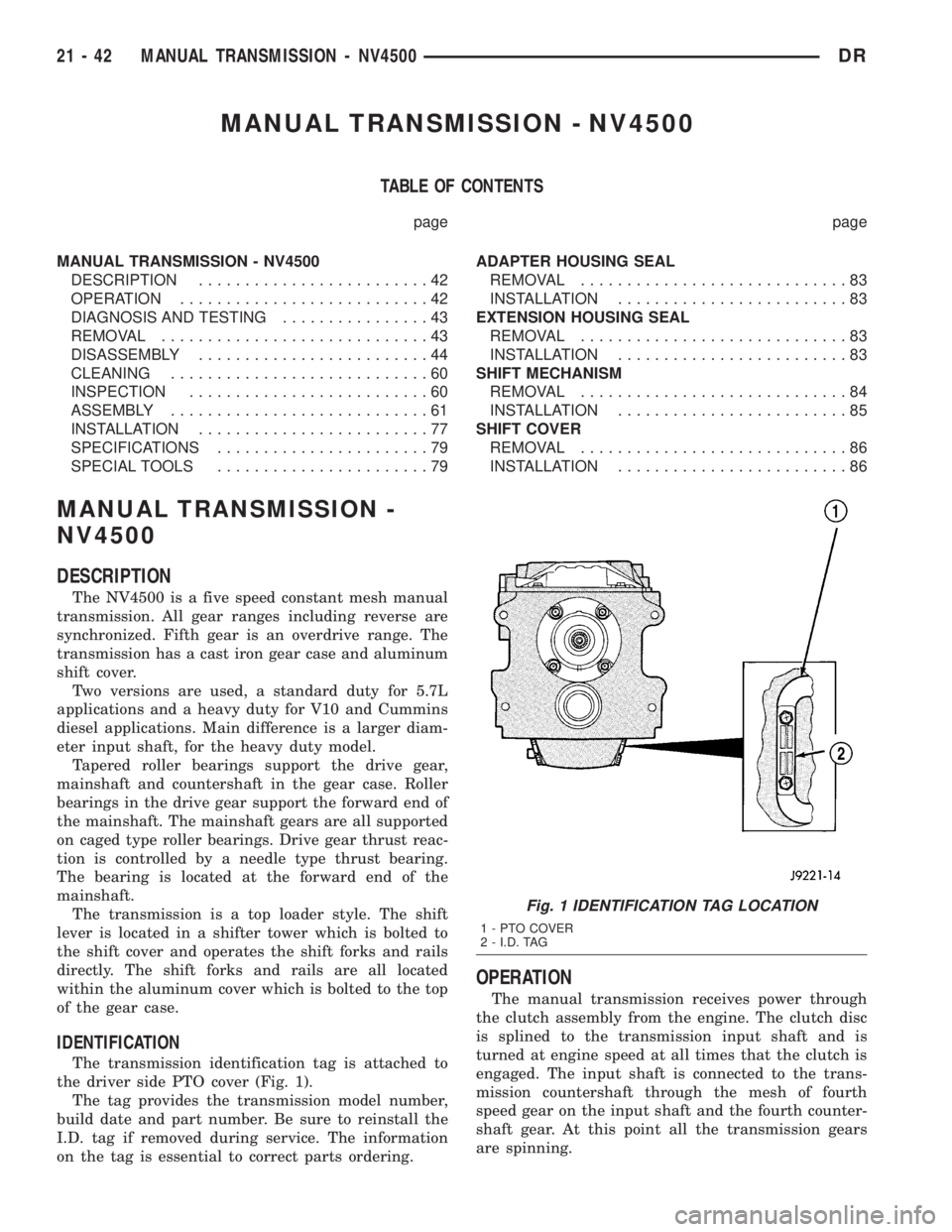
The transmission identification tag is attached to
the driver side PTO cover (Fig. 1).
The tag provides the transmission model number,
build date and part number. Be sure to reinstall the
I.D. tag if removed during service. The information
on the tag is essential to correct parts ordering.
OPERATION
The manual transmission receives power through
the clutch assembly from the engine. The clutch disc
is splined to the transmission input shaft and is
turned at engine speed at all times that the clutch is
engaged. The input shaft is connected to the trans-
mission countershaft through the mesh of fourth
speed gear on the input shaft and the fourth counter-
shaft gear. At this point all the transmission gears
are spinning.
Fig. 1 IDENTIFICATION TAG LOCATION
1 - PTO COVER
2 - I.D. TAG
21 - 42 MANUAL TRANSMISSION - NV4500DR
Page 1882 of 2895
The driver selects a particular gear by moving the
shift lever to the desired gear position. This move-
ment moves the internal transmission shift compo-
nents to begin the shift sequence. As the shift lever
moves the selected shift rail, the shift fork attached
to that rail begins to move. The fork is positioned in
a groove in the outer circumference of the synchro-
nizer sleeve. As the shift fork moves the synchronizer
sleeve, the synchronizer begins to speed-up or slow
down the selected gear (depending on whether the
driver is up-shifting or down-shifting). The synchro-
nizer does this by having the synchronizer hub
splined to the mainshaft, or the countershaft in some
cases, and moving the blocker ring into contact with
the gear's friction cone. As the blocker ring and fric-
tion cone come together, the gear speed is brought up
or down to the speed of the synchronizer. As the two
speeds match, the splines on the inside of the syn-
chronizer sleeve become aligned with the teeth on
the blocker ring and the friction cone and eventually
will slide over the teeth, locking the gear to the
mainshaft, or countershaft, through the synchronizer.
DIAGNOSIS AND TESTING
LOW LUBRICANT LEVEL
A low transmission lubricant level is generally the
result of a leak, inadequate lubricant fill or an incor-
rect lubricant level check. A correct lubricant level
check can only be made when the vehicle is level.
Also allow the lubricant to settle for a minute or so
before checking. These recommendations will ensure
an accurate check and avoid an underfill or overfill
condition. Always check the lubricant level after any
addition of fluid to avoid an incorrect lubricant level
condition.
Leaks can occur at the mating surfaces of the gear
case, adaptor or extension housing, or from the front/
rear seals. A suspected leak could also be the result
of an overfill condition. Leaks at the rear of the
extension or adapter housing will be from the hous-
ing oil seals. Leaks at component mating surfaces
will probably be the result of inadequate sealer, gaps
in the sealer, incorrect bolt tightening or use of a
non-recommended sealer. A leak at the front of the
transmission will be from either the front bearing
retainer or retainer seal. Lubricant may be seen drip-
ping from the clutch housing after extended opera-
tion. If the leak is severe, it may also contaminate
the clutch disc causing the disc to slip, grab and or
chatter.
HARD SHIFTING
Hard shifting is usually caused by a low lubricant
level, improper or contaminated lubricants. The con-
sequence of using non-recommended lubricants isnoise, excessive wear, internal bind and hard shift-
ing. Substantial lubricant leaks can result in gear,
shift rail, synchro, and bearing damage. If a leak
goes undetected for an extended period, the first indi-
cations of component damage are usually hard shift-
ing and noise.
Component damage, incorrect clutch adjustment or
damaged clutch pressure plate or disc are additional
probable causes of increased shift effort. Incorrect
adjustment or a worn/damaged pressure plate or disc
can cause incorrect release. If clutch problem is
advanced, gear clash during shifts can result. Worn
or damaged synchro rings can cause gear clash when
shifting into any forward gear. In some new or
rebuilt transmissions, new synchro rings may tend to
stick slightly causing hard or noisy shifts. In most
cases this condition will decline as the rings wear-in.
TRANSMISSION NOISE
Most manual transmissions make some noise dur-
ing normal operation. Rotating gears generate a mild
whine that is audible, but generally only at extreme
speeds. Severe highly audible transmission noise is
generally the initial indicator of a lubricant problem.
Insufficient, improper or contaminated lubricant
will promote rapid wear of gears, synchros, shift
rails, forks and bearings. The overheating caused by
a lubricant problem, can also lead to gear breakage.
REMOVAL
(1) Shift transmission into Neutral.
(2) Remove shift boot screws from floorpan and
slide boot upward on the shift lever.
(3) Remove shift lever extension from shift tower
and lever assembly.
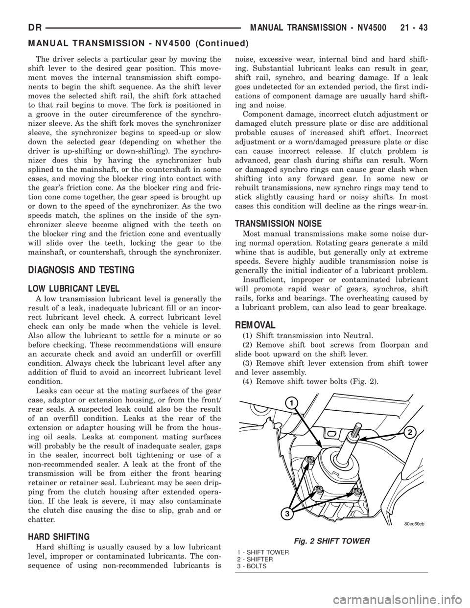
(4) Remove shift tower bolts (Fig. 2).
Fig. 2 SHIFT TOWER
1 - SHIFT TOWER
2 - SHIFTER
3 - BOLTS
DRMANUAL TRANSMISSION - NV4500 21 - 43
MANUAL TRANSMISSION - NV4500 (Continued)
Page 1883 of 2895
(5) Remove shift tower and isolator plate from
transmission shift cover.
(6) Raise and support vehicle.
(7) Remove skid plate, if equipped.
(8) Mark propeller shaft and axle yokes for instal-
lation reference and remove shaft/shafts.
(9) Remove exhaust system Y-pipe.
(10) Disconnect speed sensor and backup light
switch connectors.
(11) Support engine with safety stand and a wood
block.
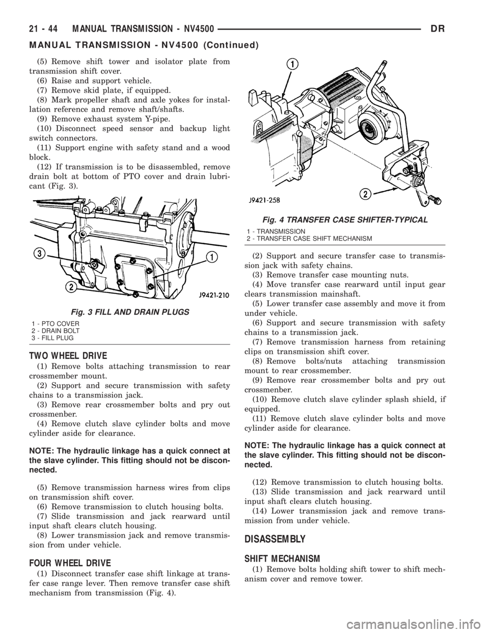
(12) If transmission is to be disassembled, remove
drain bolt at bottom of PTO cover and drain lubri-
cant (Fig. 3).
TWO WHEEL DRIVE
(1) Remove bolts attaching transmission to rear
crossmember mount.
(2) Support and secure transmission with safety
chains to a transmission jack.
(3) Remove rear crossmember bolts and pry out
crossmenber.
(4) Remove clutch slave cylinder bolts and move
cylinder aside for clearance.
NOTE: The hydraulic linkage has a quick connect at
the slave cylinder. This fitting should not be discon-
nected.
(5) Remove transmission harness wires from clips
on transmission shift cover.
(6) Remove transmission to clutch housing bolts.
(7) Slide transmission and jack rearward until
input shaft clears clutch housing.
(8) Lower transmission jack and remove transmis-
sion from under vehicle.
FOUR WHEEL DRIVE
(1) Disconnect transfer case shift linkage at trans-
fer case range lever. Then remove transfer case shift
mechanism from transmission (Fig. 4).(2) Support and secure transfer case to transmis-
sion jack with safety chains.
(3) Remove transfer case mounting nuts.
(4) Move transfer case rearward until input gear
clears transmission mainshaft.
(5) Lower transfer case assembly and move it from
under vehicle.
(6) Support and secure transmission with safety
chains to a transmission jack.
(7) Remove transmission harness from retaining
clips on transmission shift cover.
(8) Remove bolts/nuts attaching transmission
mount to rear crossmember.
(9) Remove rear crossmember bolts and pry out
crossmenber.
(10) Remove clutch slave cylinder splash shield, if
equipped.
(11) Remove clutch slave cylinder bolts and move
cylinder aside for clearance.
NOTE: The hydraulic linkage has a quick connect at
the slave cylinder. This fitting should not be discon-
nected.
(12) Remove transmission to clutch housing bolts.
(13) Slide transmission and jack rearward until
input shaft clears clutch housing.
(14) Lower transmission jack and remove trans-
mission from under vehicle.
DISASSEMBLY
SHIFT MECHANISM
(1) Remove bolts holding shift tower to shift mech-
anism cover and remove tower.
Fig. 3 FILL AND DRAIN PLUGS
1 - PTO COVER
2 - DRAIN BOLT
3 - FILL PLUG
Fig. 4 TRANSFER CASE SHIFTER-TYPICAL
1 - TRANSMISSION
2 - TRANSFER CASE SHIFT MECHANISM
21 - 44 MANUAL TRANSMISSION - NV4500DR
MANUAL TRANSMISSION - NV4500 (Continued)
Page 2033 of 2895
(4) Tighten adjusting screw to 8 N´m (72 in. lbs.)
torque (Fig. 79).
(5) Back off adjusting screw 2 turns.
(6) Hold adjusting screw in place and tighten lock-
nut to 34 N´m (25 ft. lbs.) torque.
(7) Position new gasket on oil pan and install pan
on transmission. Tighten pan bolts to 13.6 N´m (125
in. lbs.) torque.
(8) Lower vehicle and refill transmission with
MopartATF +4, Automatic Transmission fluid.
BRAKE TRANSMISSION SHIFT
INTERLOCK SYSTEM
DESCRIPTION
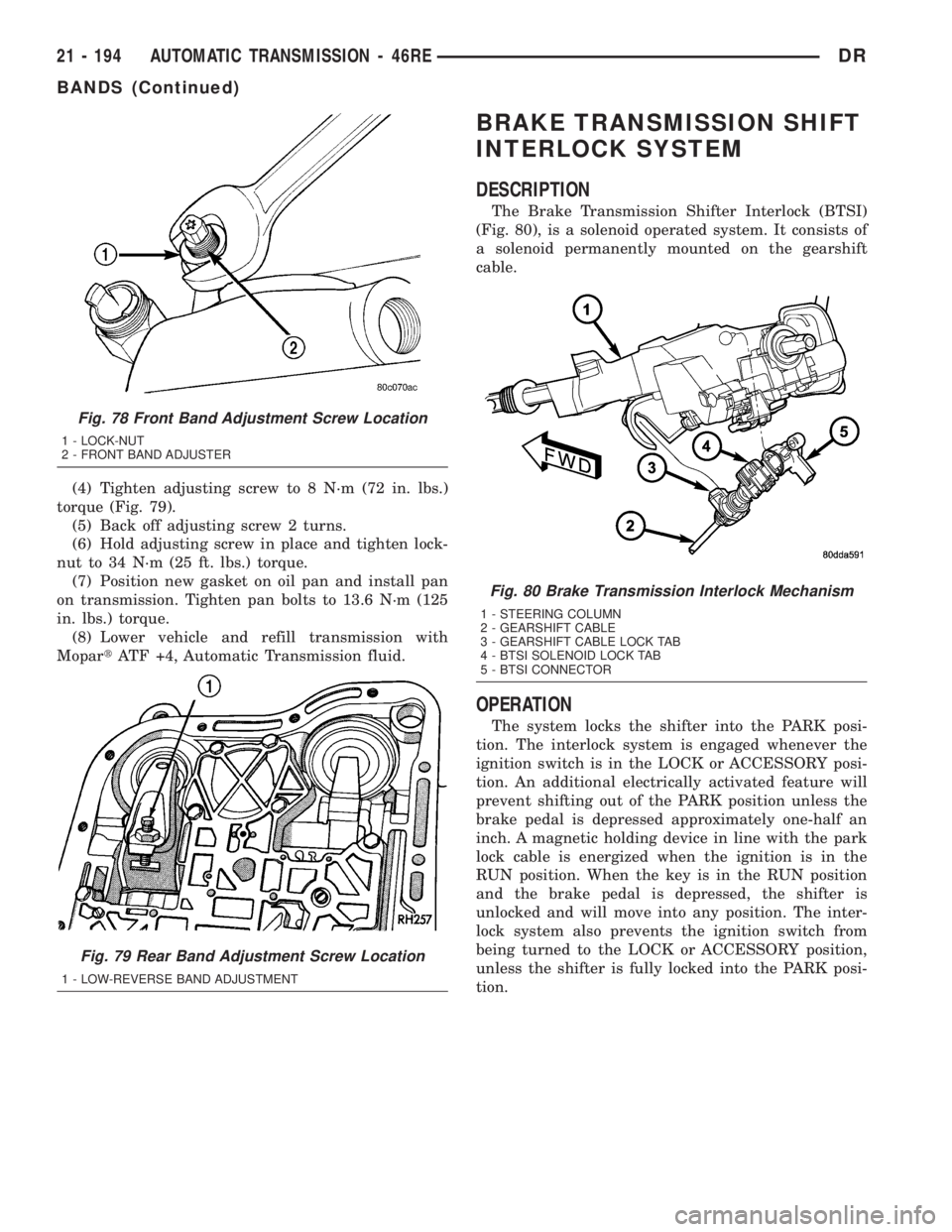
The Brake Transmission Shifter Interlock (BTSI)
(Fig. 80), is a solenoid operated system. It consists of
a solenoid permanently mounted on the gearshift
cable.
OPERATION
The system locks the shifter into the PARK posi-
tion. The interlock system is engaged whenever the
ignition switch is in the LOCK or ACCESSORY posi-
tion. An additional electrically activated feature will
prevent shifting out of the PARK position unless the
brake pedal is depressed approximately one-half an
inch. A magnetic holding device in line with the park
lock cable is energized when the ignition is in the
RUN position. When the key is in the RUN position
and the brake pedal is depressed, the shifter is
unlocked and will move into any position. The inter-
lock system also prevents the ignition switch from
being turned to the LOCK or ACCESSORY position,
unless the shifter is fully locked into the PARK posi-
tion.
Fig. 78 Front Band Adjustment Screw Location
1 - LOCK-NUT
2 - FRONT BAND ADJUSTER
Fig. 79 Rear Band Adjustment Screw Location
1 - LOW-REVERSE BAND ADJUSTMENT
Fig. 80 Brake Transmission Interlock Mechanism
1 - STEERING COLUMN
2 - GEARSHIFT CABLE
3 - GEARSHIFT CABLE LOCK TAB
4 - BTSI SOLENOID LOCK TAB
5 - BTSI CONNECTOR
21 - 194 AUTOMATIC TRANSMISSION - 46REDR
BANDS (Continued)
Page 2034 of 2895
DIAGNOSIS AND TESTING - BRAKE
TRANSMISSION SHIFT INTERLOCK
(1) Verify that the key can only be removed in the
PARK position
(2) When the shift lever is in PARK And the shift
handle pushbutton is in the ªOUTº position, the igni-
tion key cylinder should rotate freely from OFF to
LOCK. When the shifter is in any other gear or neu-
tral position, the ignition key cylinder should not
rotate to the LOCK position.
(3) Shifting out of PARK should not be possible
when the ignition key cylinder is in the OFF posi-
tion.
(4) Shifting out of PARK should not be possible
while applying normal pushbutton force and ignition
key cylinder is in the RUN or START positions
unless the foot brake pedal is depressed approxi-
mately 1/2 inch (12mm).
(5) Shifting out of PARK should not be possible
when the ignition key cylinder is in the ACCESSORY
or LOCK positions.
(6) Shifting between any gears, NEUTRAL or into
PARK may be done without depressing foot brake
pedal with ignition switch in RUN or START posi-
tions.
ADJUSTMENTS - BRAKE TRANSMISSION
SHIFT INTERLOCK
Correct cable adjustment is important to proper
interlock operation. The gearshift cable must be cor-
rectly adjusted in order to shift out of PARK.
ADJUSTMENT PROCEDURE
(1) Remove the steering column trim as necessary
for access to the brake transmission shift interlock.
(2) Shift the transmission into the PARK position.
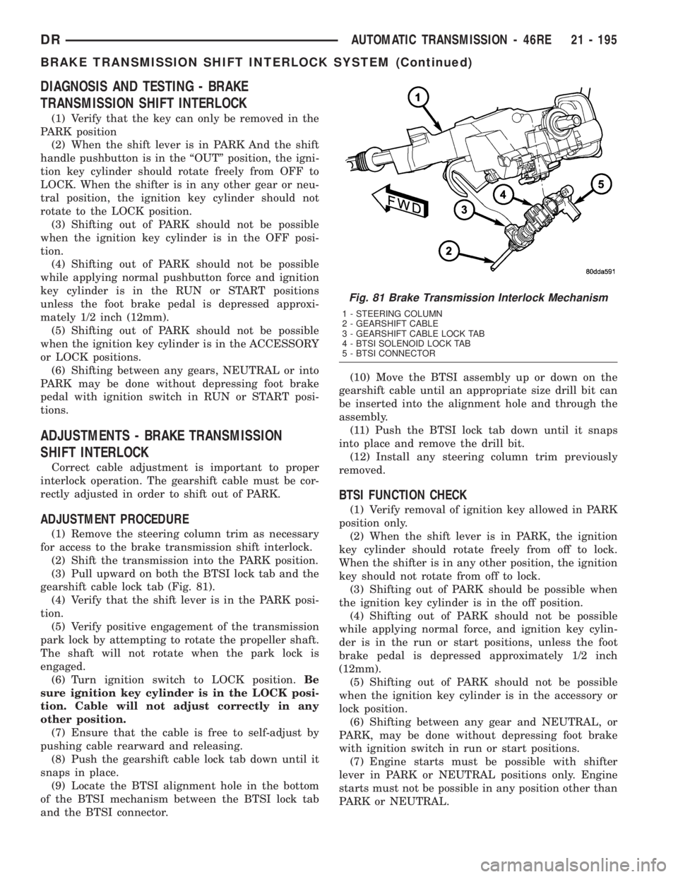
(3) Pull upward on both the BTSI lock tab and the
gearshift cable lock tab (Fig. 81).
(4) Verify that the shift lever is in the PARK posi-
tion.
(5) Verify positive engagement of the transmission
park lock by attempting to rotate the propeller shaft.
The shaft will not rotate when the park lock is
engaged.
(6) Turn ignition switch to LOCK position.Be
sure ignition key cylinder is in the LOCK posi-
tion. Cable will not adjust correctly in any
other position.
(7) Ensure that the cable is free to self-adjust by
pushing cable rearward and releasing.
(8) Push the gearshift cable lock tab down until it
snaps in place.
(9) Locate the BTSI alignment hole in the bottom
of the BTSI mechanism between the BTSI lock tab
and the BTSI connector.(10) Move the BTSI assembly up or down on the
gearshift cable until an appropriate size drill bit can
be inserted into the alignment hole and through the
assembly.
(11) Push the BTSI lock tab down until it snaps
into place and remove the drill bit.
(12) Install any steering column trim previously
removed.
BTSI FUNCTION CHECK
(1) Verify removal of ignition key allowed in PARK
position only.
(2) When the shift lever is in PARK, the ignition
key cylinder should rotate freely from off to lock.
When the shifter is in any other position, the ignition
key should not rotate from off to lock.
(3) Shifting out of PARK should be possible when
the ignition key cylinder is in the off position.
(4) Shifting out of PARK should not be possible
while applying normal force, and ignition key cylin-
der is in the run or start positions, unless the foot
brake pedal is depressed approximately 1/2 inch
(12mm).
(5) Shifting out of PARK should not be possible
when the ignition key cylinder is in the accessory or
lock position.
(6) Shifting between any gear and NEUTRAL, or
PARK, may be done without depressing foot brake
with ignition switch in run or start positions.
(7) Engine starts must be possible with shifter
lever in PARK or NEUTRAL positions only. Engine
starts must not be possible in any position other than
PARK or NEUTRAL.
Fig. 81 Brake Transmission Interlock Mechanism
1 - STEERING COLUMN
2 - GEARSHIFT CABLE
3 - GEARSHIFT CABLE LOCK TAB
4 - BTSI SOLENOID LOCK TAB
5 - BTSI CONNECTOR
DRAUTOMATIC TRANSMISSION - 46RE 21 - 195
BRAKE TRANSMISSION SHIFT INTERLOCK SYSTEM (Continued)