Page 1013 of 1767
SYMPTOM MATRIX CHART 2
(Non self-diagnosis related item)
SYMPTOMDIAGNOSTIC PROCEDURE
(Reference page)SYSTEM
(Malfunctioning part or mode)REFERENCE PART
NO. OF ILLUSTRATION
ON NEXT PAGE
ISecurity ind. does not light up.PROCEDURE 6
(EL-205)Security ind.
Open circuit between Fuse and
NATS IMMU
Continuation of initialization mode
NATS IMMU
Security ind. does not blink just
after initialization even if the vehicle
is equipped with dongle unit.
PROCEDURE 8
(EL-207)NATS might be initialized without connecting dongle unit properly.
Open circuit in ground line of
dongle control circuitC6
Security ind. does not blink just
after ignition switch is turned to ON
when some malfunction related to
NATS is detected even if the
vehicle is equipped with dongle
unit.Open or short circuit in communica-
tion line between IMMU and dongle
control unitC5
Dongle control unit G
DIAGNOSTIC SYSTEM DIAGRAM
NEL559
NATS (Nissan Anti-Theft System)
Trouble Diagnoses (Cont'd)
EL-197
Page 1021 of 1767

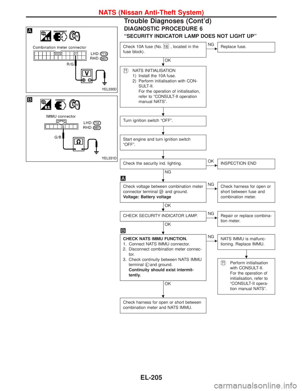
DIAGNOSTIC PROCEDURE 6
ªSECURITY INDICATOR LAMP DOES NOT LIGHT UPº
Check 10A fuse (No.16 , located in the
fuse block).
OK
ENG
Replace fuse.
NATS INITIALISATION
1) Install the 10A fuse.
2) Perform initialisation with CON-
SULT-II.
For the operation of initialisation,
refer to ªCONSULT-II operation
manual NATSº.
Turn ignition switch ªOFFº.
Start engine and turn ignition switch
ªOFFº.
Check the security ind. lighting.
NG
EOK
INSPECTION END
Check voltage between combination meter
connector terminalq
27and ground.
Voltage: Battery voltage
OK
ENG
Check harness for open or
short between fuse and
combination meter.
CHECK SECURITY INDICATOR LAMP.
OK
ENG
Repair or replace combina-
tion meter.
CHECK NATS IMMU FUNCTION.
1. Connect NATS IMMU connector.
2. Disconnect combination meter connec-
tor.
3. Check continuity between NATS IMMU
terminalq
5and ground.
Continuity should exist intermit-
tently.
OK
ENG
NATS IMMU is malfunc-
tioning. Replace IMMU.
Perform initialisation
with CONSULT-II.
For the operation of
initialisation, refer to
ªCONSULT-II opera-
tion manual NATSº.
Check harness for open or short between
combination meter and NATS IMMU.
YEL330D
YEL331D
H
H
H
H
H
H
H
H
H
NATS (Nissan Anti-Theft System)
Trouble Diagnoses (Cont'd)
EL-205
Page 1107 of 1767

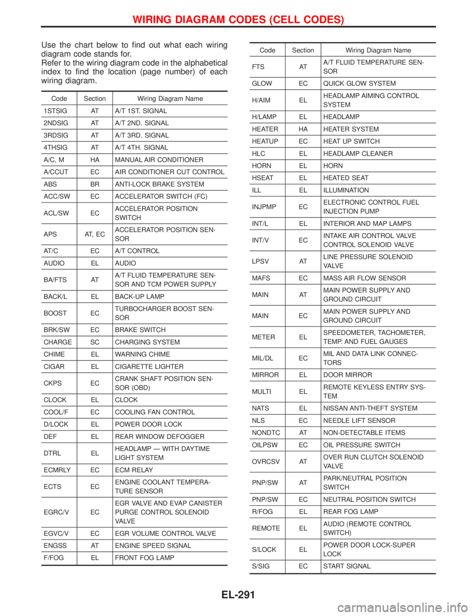
Use the chart below to find out what each wiring
diagram code stands for.
Refer to the wiring diagram code in the alphabetical
index to find the location (page number) of each
wiring diagram.
Code Section Wiring Diagram Name
1STSIG AT A/T 1ST. SIGNAL
2NDSIG AT A/T 2ND. SIGNAL
3RDSIG AT A/T 3RD. SIGNAL
4THSIG AT A/T 4TH. SIGNAL
A/C, M HA MANUAL AIR CONDITIONER
A/CCUT EC AIR CONDITIONER CUT CONTROL
ABS BR ANTI-LOCK BRAKE SYSTEM
ACC/SW EC ACCELERATOR SWITCH (FC)
ACL/SW ECACCELERATOR POSITION
SWITCH
APS AT, ECACCELERATOR POSITION SEN-
SOR
AT/C EC A/T CONTROL
AUDIO EL AUDIO
BA/FTS ATA/T FLUID TEMPERATURE SEN-
SOR AND TCM POWER SUPPLY
BACK/L EL BACK-UP LAMP
BOOST ECTURBOCHARGER BOOST SEN-
SOR
BRK/SW EC BRAKE SWITCH
CHARGE SC CHARGING SYSTEM
CHIME EL WARNING CHIME
CIGAR EL CIGARETTE LIGHTER
CKPS ECCRANK SHAFT POSITION SEN-
SOR (OBD)
CLOCK EL CLOCK
COOL/F EC COOLING FAN CONTROL
D/LOCK EL POWER DOOR LOCK
DEF EL REAR WINDOW DEFOGGER
DTRL ELHEADLAMP Ð WITH DAYTIME
LIGHT SYSTEM
ECMRLY EC ECM RELAY
ECTS ECENGINE COOLANT TEMPERA-
TURE SENSOR
EGRC/V ECEGR VALVE AND EVAP CANISTER
PURGE CONTROL SOLENOID
VA LV E
EGVC/V EC EGR VOLUME CONTROL VALVE
ENGSS AT ENGINE SPEED SIGNAL
F/FOG EL FRONT FOG LAMP
Code Section Wiring Diagram Name
FTS ATA/T FLUID TEMPERATURE SEN-
SOR
GLOW EC QUICK GLOW SYSTEM
H/AIM ELHEADLAMP AIMING CONTROL
SYSTEM
H/LAMP EL HEADLAMP
HEATER HA HEATER SYSTEM
HEATUP EC HEAT UP SWITCH
HLC EL HEADLAMP CLEANER
HORN EL HORN
HSEAT EL HEATED SEAT
ILL EL ILLUMINATION
INJPMP ECELECTRONIC CONTROL FUEL
INJECTION PUMP
INT/L EL INTERIOR AND MAP LAMPS
INT/V ECINTAKE AIR CONTROL VALVE
CONTROL SOLENOID VALVE
LPSV ATLINE PRESSURE SOLENOID
VA LV E
MAFS EC MASS AIR FLOW SENSOR
MAIN ATMAIN POWER SUPPLY AND
GROUND CIRCUIT
MAIN ECMAIN POWER SUPPLY AND
GROUND CIRCUIT
METER ELSPEEDOMETER, TACHOMETER,
TEMP. AND FUEL GAUGES
MIL/DL ECMIL AND DATA LINK CONNEC-
TORS
MIRROR EL DOOR MIRROR
MULTI ELREMOTE KEYLESS ENTRY SYS-
TEM
NATS EL NISSAN ANTI-THEFT SYSTEM
NLS EC NEEDLE LIFT SENSOR
NONDTC AT NON-DETECTABLE ITEMS
OILPSW EC OIL PRESSURE SWITCH
OVRCSV ATOVER RUN CLUTCH SOLENOID
VA LV E
PNP/SW ATPARK/NEUTRAL POSITION
SWITCH
PNP/SW EC NEUTRAL POSITION SWITCH
R/FOG EL REAR FOG LAMP
REMOTE ELAUDIO (REMOTE CONTROL
SWITCH)
S/LOCK ELPOWER DOOR LOCK-SUPER
LOCK
S/SIG EC START SIGNAL
WIRING DIAGRAM CODES (CELL CODES)
EL-291
Page 1132 of 1767
Removal and Installation
REMOVAL
1. Remove the following parts.
IRadiator under side
IRadiator shroud
ICooling fan
IChain cover front side
IA/T cooler hose (Disconnect)
IVacuum hose
IIntercooler cover (When removing vacuum tank)
2. Remove the installation bolts and pull the vacuum pump from
the engine front directly.
3. If it is difficult to remove from the spline shaft connection, tap
lightly with a plastic hammer.
SEM320G
SEM321G
VACUUM PUMPZD
EM-24
Page 1154 of 1767
Installation
1. Install the front plate.
1) Install the O-ring and gasket to the cylinder block.
2) Install the front plate.
ILightly tap with a hammer if the dowel pin cannot be inserted
easily.
CAUTION:
Make sure that the O-ring does not pop out.
3) Apply Three Bond 1207C (KP510 00150) with a spreader
between the cylinder block plate under the cylinder block (oil
pan side) and the front plate (shown by the arrows in the fig-
ure).
2. Install the fuel injection pump.
IAfter installing the front plate, align the 6 mm (0.24 in) dia. hole
of the pump flange and the 6 mm (0.24 in) dia. hole position of
the pump body.
3. Install each timing gear.
IAlign the match marks of the timing gears by referring to the
figure below.
IWhen installing timing gear, follow the order (q
1,q2) shown in
the dotted box in the figure below to facilitate installation.
SEM387G
FEM041
FEM042
TIMING GEARZD
Inspection (Cont'd)
EM-46
Page 1185 of 1767

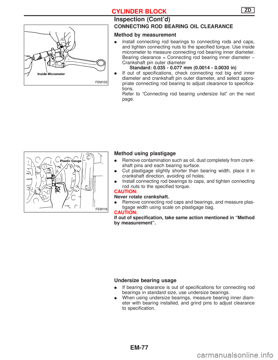
CONNECTING ROD BEARING OIL CLEARANCE
Method by measurement
IInstall connecting rod bearings to connecting rods and caps,
and tighten connecting nuts to the specified torque. Use inside
micrometer to measure connecting rod bearing inner diameter.
Bearing clearance = Connecting rod bearing inner diameter þ
Crankshaft pin outer diameter
Standard: 0.035 - 0.077 mm (0.0014 - 0.0030 in)
IIf out of specifications, check connecting rod big end inner
diameter and crankshaft pin outer diameter, and select appro-
priate connecting rod bearing to adjust clearance to specifica-
tions.
Refer to ªConnecting rod bearing undersize listº on the next
page.
Method using plastigage
IRemove contamination such as oil, dust completely from crank-
shaft pins and each bearing surface.
ICut plastigage slightly shorter than bearing width, place it in
crankshaft direction, avoiding oil holes.
IInstall connecting rod bearings to caps, and tighten connecting
rod nuts to the specified torque.
CAUTION:
Never rotate crankshaft.
IRemove connecting rod caps and bearings, and measure plas-
tigage width using scale on plastigage bag.
CAUTION:
If out of specification, take same action mentioned in ªMethod
by measurementº.
Undersize bearing usage
IIf bearing clearance is out of specifications for connecting rod
bearings in standard size, use undersize bearings.
IWhen using undersize bearings, measure bearing inner diam-
eter with bearing installed, and grind pins to adjust clearance
to specification.
FEM103
FEM118
CYLINDER BLOCKZD
Inspection (Cont'd)
EM-77
Page 1186 of 1767

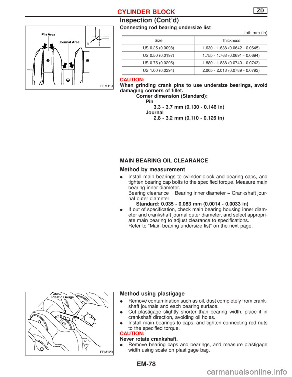
Connecting rod bearing undersize list
Unit: mm (in)
Size Thickness
US 0.25 (0.0098) 1.630 - 1.638 (0.0642 - 0.0645)
US 0.50 (0.0197) 1.755 - 1.763 (0.0691 - 0.0694)
US 0.75 (0.0295) 1.880 - 1.888 (0.0740 - 0.0743)
US 1.00 (0.0394) 2.005 - 2.013 (0.0789 - 0.0793)
CAUTION:
When grinding crank pins to use undersize bearings, avoid
damaging corners of fillet.
Corner dimension (Standard):
Pin
3.3 - 3.7 mm (0.130 - 0.146 in)
Journal
2.8 - 3.2 mm (0.110 - 0.126 in)
MAIN BEARING OIL CLEARANCE
Method by measurement
IInstall main bearings to cylinder block and bearing caps, and
tighten bearing cap bolts to the specified torque. Measure main
bearing inner diameter.
Bearing clearance = Bearing inner diameter þ Crankshaft jour-
nal outer diameter
Standard: 0.035 - 0.083 mm (0.0014 - 0.0033 in)
IIf out of specification, check main bearing housing inner diam-
eter and crankshaft journal outer diameter, and select appropri-
ate main bearing to adjust clearance to specifications.
Refer to ªMain bearing undersize listº on the next page.
Method using plastigage
IRemove contamination such as oil, dust completely from crank-
shaft journals and each bearing surface.
ICut plastigage slightly shorter than bearing width, place it in
crankshaft direction, avoiding oil holes.
IInstall main bearings to caps, and tighten connecting rod nuts
to the specified torque.
CAUTION:
Never rotate crankshaft.
IRemove bearing caps and bearings, and measure plastigage
width using scale on plastigage bag.
FEM119
FEM120
CYLINDER BLOCKZD
Inspection (Cont'd)
EM-78
Page 1278 of 1767
Removal
IRemove free-running hub assembly.
Refer to ªFRONT AXLE Ð Auto-lock Free-running Hubº, FA-14.
ISeparate drive shaft from knuckle spindle by slightly tapping
drive shaft end.
ISeparate tie-rod from knuckle spindle with Tool.
Install stud nut conversely on stud bolt so as not to damage
stud bolt.
ISeparate knuckle spindle from ball joints.
(1) Loosen (not remove) upper and lower ball joint tightening nuts.
(2) Separate upper and lower ball joints to knuckle spindle with
Tool.
During above operation, never remove ball joint nuts which
are loosened in step (1) above.
Tool: HT72520000
NFA008
NFA009
NFA010
SFA927
SFA079
FRONT AXLE Ð Knuckle Spindle
FA-20