2002 NISSAN TERRANO light
[x] Cancel search: lightPage 1364 of 1767
HFC-134a (R-134a) Service Tools and
Equipment
It is important to understand that HFC-134a (R-134a) refrigerant, and the specified lubricant which must be
used with HFC-134a (R-134a), must never be mixed with CFC-12 (R-12) refrigerant and/or the CFC-12 (R-12)
lubricant.
This means that separate and non-interchangeable service equipment must be used for handling each type
of refrigerant/lubricant.
To prevent the mixing of refrigerants/lubricants, refrigerant container fittings, service hose fittings, and service
equipment fittings (equipment which handles refrigerant and/or lubricant) are different between CFC-12 (R-12)
and HFC-134a (R-134a).
Adaptors to convert from one size of fitting to another must never be used: refrigerant/lubricant contamination
will occur and compressor failure will result.
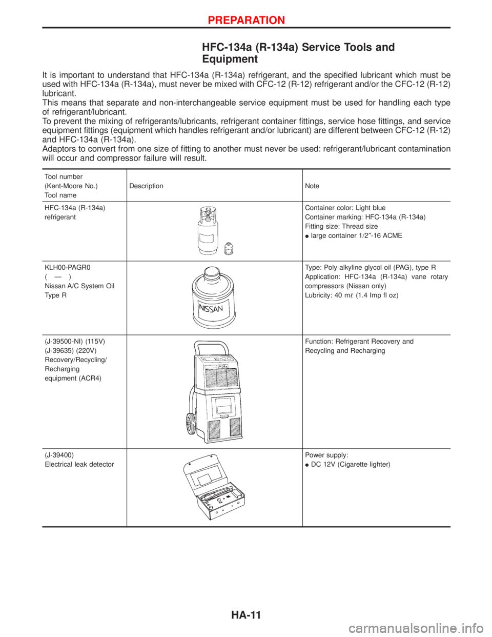
Tool number
(Kent-Moore No.)
Tool nameDescription Note
HFC-134a (R-134a)
refrigerant
Container color: Light blue
Container marking: HFC-134a (R-134a)
Fitting size: Thread size
Ilarge container 1/2²-16 ACME
KLH00-PAGR0
(Ð)
Nissan A/C System Oil
Type R
Type: Poly alkyline glycol oil (PAG), type R
Application: HFC-134a (R-134a) vane rotary
compressors (Nissan only)
Lubricity: 40 m(1.4 Imp fl oz)
(J-39500-NI) (115V)
(J-39635) (220V)
Recovery/Recycling/
Recharging
equipment (ACR4)
Function: Refrigerant Recovery and
Recycling and Recharging
(J-39400)
Electrical leak detector
Power supply:
IDC 12V (Cigarette lighter)
PREPARATION
HA-11
Page 1381 of 1767
Operation Check
The purpose of the operational check is to confirm that the system
is as it should be. The systems which will be checked are the
blower, mode (discharge air), intake air, temperature decrease,
temperature increase and A/C switch system.
CONDITIONS:
Engine running and at normal operating temperature.
PROCEDURE:
1. Check blower
1) Turn FAN CONTROL DIAL to 1.
Blower should operate at speed 1.
2) Then turn the DIAL to speed 2.
3) Continue checking blower speed until all speeds are checked.
4) Leave blower on speed 4.
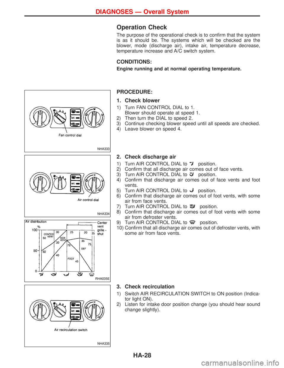
2. Check discharge air
1) Turn AIR CONTROL DIAL toposition.
2) Confirm that all discharge air comes out of face vents.
3) Turn AIR CONTROL DIAL to
position.
4) Confirm that discharge air comes out of face vents and foot
vents.
5) Turn AIR CONTROL DIAL to
position.
6) Confirm that discharge air comes out of foot vents, with some
air from face vents.
7) Turn AIR CONTROL DIAL to
position.
8) Confirm that discharge air comes out of foot vents with some
air from defroster vents.
9) Turn AIR CONTROL DIAL to
position.
10) Confirm that all discharge air comes out of defroster vents, with
some air from face vents.
3. Check recirculation
1) Switch AIR RECIRCULATION SWITCH to ON position (Indica-
tor light ON).
2) Listen for intake door position change (you should hear sound
change slightly).
NHA333
NHA334
RHA035E
NHA335
DIAGNOSES Ð Overall System
HA-28
Page 1382 of 1767
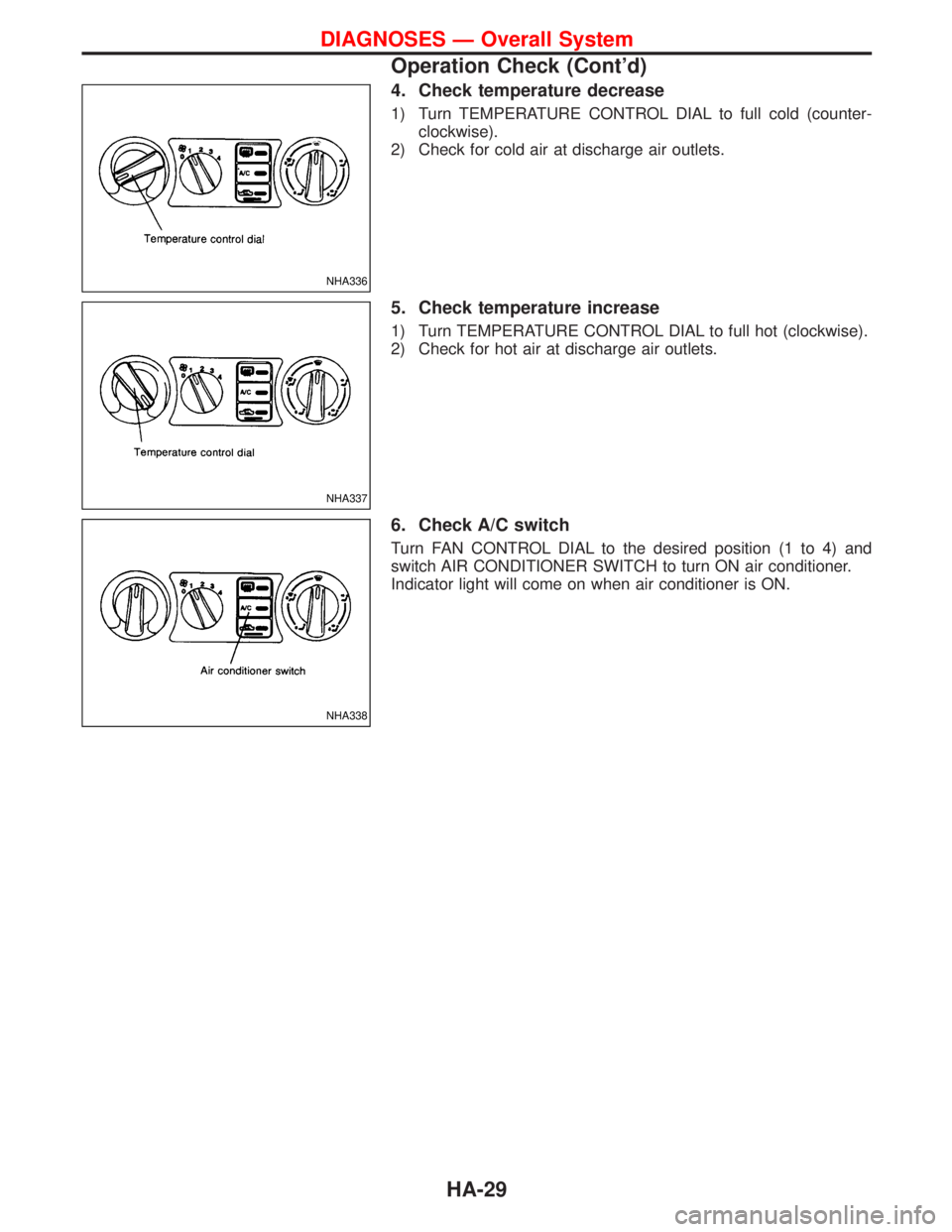
4. Check temperature decrease
1) Turn TEMPERATURE CONTROL DIAL to full cold (counter-
clockwise).
2) Check for cold air at discharge air outlets.
5. Check temperature increase
1) Turn TEMPERATURE CONTROL DIAL to full hot (clockwise).
2) Check for hot air at discharge air outlets.
6. Check A/C switch
Turn FAN CONTROL DIAL to the desired position (1 to 4) and
switch AIR CONDITIONER SWITCH to turn ON air conditioner.
Indicator light will come on when air conditioner is ON.
NHA336
NHA337
NHA338
DIAGNOSES Ð Overall System
Operation Check (Cont'd)
HA-29
Page 1419 of 1767
A
ABS (anti-lock brake system).........................BR-35
ABS - Wiring diagram ....................................BR-50
A/C air flow .......................................................HA-8
A/C compressor precaution..............................HA-5
A/C control operation (manual A/C) .................HA-6
A/C relay.........................................................HA-61
A/C symptom chart (manual A/C) ..................HA-36
A/C trouble diagnoses (manual A/C) .............HA-27
A/C, M - Wiring diagram ................................HA-43
ACC/SW - Wiring diagram ...........................EC-106
Accelerator control system ...........................FE-2, 5
Accelerator position sensor .........EC-130, 368, 371
Accelerator position switch ..................EC-369, 371
Accelerator switch (F/C) ...............................EC-104
Accelerator wire adjustment .............................FE-5
Accelerator work unit....................................EC-365
A/CCUT - Wiring diagram ............................EC-289
Air bag ..............................................................RS-6
Air bag disposal..............................................RS-20
Air bag precautions ...........................................GI-3
Air bleeding (hydraulic clutch) ..........................CL-6
Air bleeding for brake system ..........................BR-8
Air cleaner filter replacement ..............MA-5, 20, 24
Air conditioner cut control ..............EC-22, 311, 440
Air control cable adjustment...........................HA-62
Air flow meter - See Mass air flow
sensor .................................................EC-88, 356
Alternator ........................................................SC-27
Angular tightening application..........................EM-3
Antenna .................................................EL-111, 127
Anti-lock brake system - See ABS .................BR-37
Anti-lock brake system - Wiring
diagram .......................................................BR-50
APS - Wiring diagram ..................................EC-133
ASCD vacuum hose ......................................MA-40
A/T - Wiring diagram .........................................AT-7
A/T - Wiring diagram - AT - PNP/SW .............AT-87
A/T - Wiring diagram - AT - VSS A/T ..............AT-49
A/T control ....................................................EC-155
A/T diagnosis communication line ...............EC-155
A/T fluid checking ............................................AT-27
A/T fluid temperature sensor...........................AT-76
A/T mode switch..............................................AT-94
A/T self-diagnoses ....................................AT-14, 19
A/T Wiring diagram - AT - ENG SS ................AT-79
A/T Wiring diagram AT - BA/FTS ....................AT-75
A/T Wiring diagram AT - LPSV .......................AT-82
A/T Wiring diagram AT - OVRCSV .................AT-68
A/T Wiring diagram AT - SSV/A ......................AT-62
A/T Wiring diagram AT - SSV/B ......................AT-65
A/T Wiring diagram AT - TCV .........................AT-71
A/T Wiring diagram AT - TPS..........................AT-56
A/T Wiring diagram AT - VSSMTR .................AT-52
AT/C - Wiring diagram..................................EC-157
Audio......................................................EL-111, 113
AUDIO - Wiring diagram ...............................EL-115Audio and A/C control removal and
installation - See Instrument panel .............BT-16
Auto lock free running hub .............................FA-14
Automatic transmission number ......................GI-30
Axle housing (rear) ...........................................RA-8
B
Back Door .......................................................BT-14
Back door opener - See Back door ................BT-14
Back door trim.................................................BT-18
Back door window...........................................BT-43
Back-up lamp ..................................................EL-49
Back-up lamp switch (M/T) ........................MT-6, 10
BACK/L - Wiring diagram................................EL-49
Ball joint front axle ..........................................FA-36
Basic inspection .....................................EC-50, 338
Battery ..............................................................SC-3
Battery Voltage .............................................EC-153
Blower motor ..................................................HA-60
Blower resistor................................................HA-60
Body alignment ...............................................BT-49
BOOST - Wiring diagram .............................EC-217
Boring/horning cylinder block.........................EM-74
Brake booster .................................................BR-17
Brake fluid change ...........................................BR-5
Brake fluid level ...........................MA-17, 36, 40, 43
Brake fluid level and line check .......................BR-5
Brake hydraulic line......................................BR-5, 6
Brake inspection ..........................MA-36, 40, 41, 42
Brake lines and cables inspection.....MA-36, 40, 42
Brake lining wear temporary checking ....MA-36, 42
Brake master cylinder ....................................BR-16
Brake pedal ....................................................BR-14
Brake switch .................................................EC-400
BRK/SW - Wiring diagram ...........................EC-205
Bumper, front ....................................................BT-6
Bumper, rear .....................................................BT-8
C
Camshaft ........................................................EM-30
Camshaft position sensor (PUMP)...............EC-161
Center case (Transfer) ......................................TF-9
CHARGE - Wiring diagram ............................SC-24
Charge air pressure sensor .........................EC-215
Charging system ............................................SC-23
Chassis and body maintenance ....................MA-36
CIGAR - Wiring diagram ...............................EL-105
Cigarette lighter.............................................EL-104
Circuit breaker.................................................EL-17
CKPS - Wiring diagram ................................EC-147
Clock .............................................................EL-104
CLOCK - Wiring diagram ..............................EL-106
Clutch cover ..............................................CL-11, 12
Clutch disc ......................................................CL-11
Clutch fluid level ......................................MA-17, 36
Clutch master cylinder ..................................CL-7, 8
ALPHABETICAL INDEX
IDX-2
Page 1420 of 1767
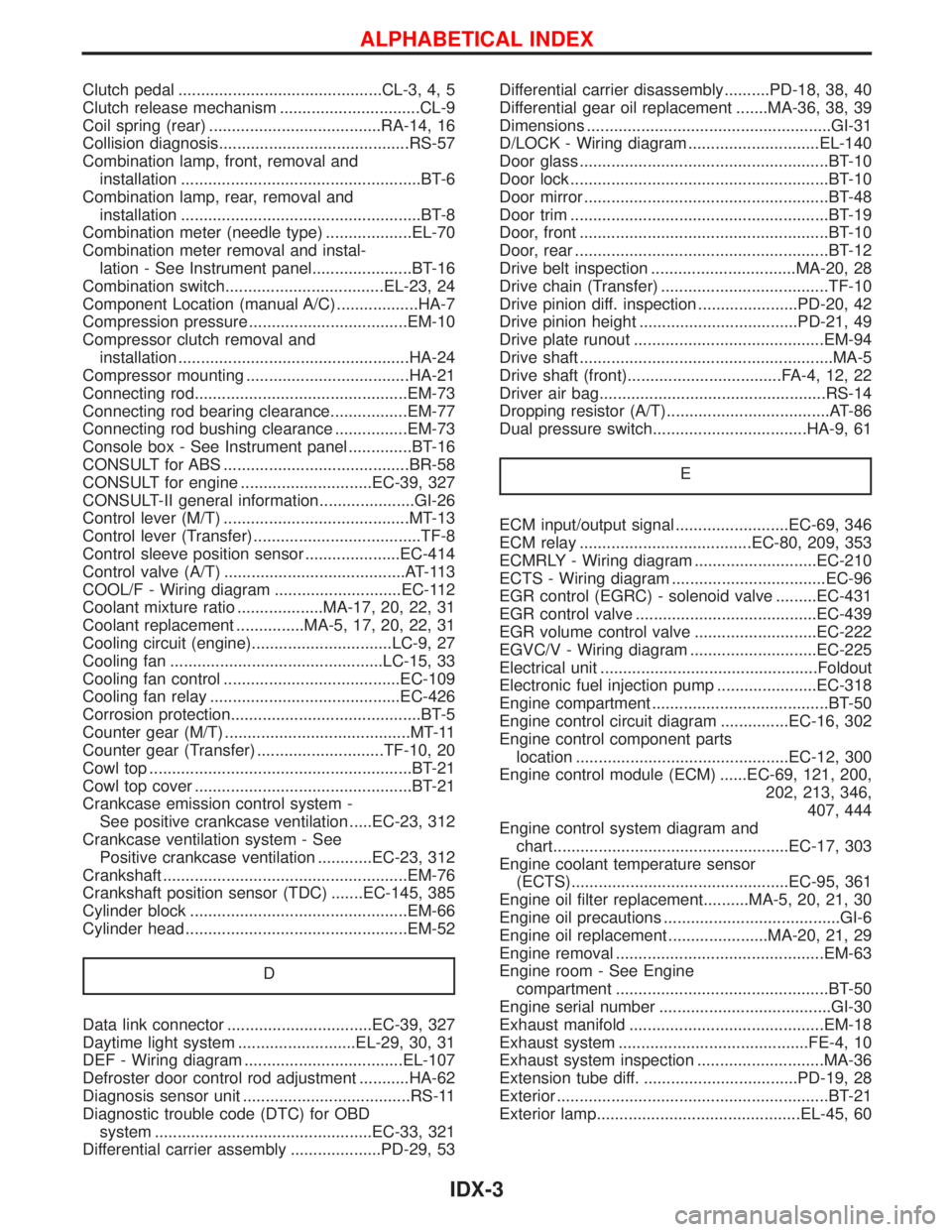
Clutch pedal .............................................CL-3, 4, 5
Clutch release mechanism ...............................CL-9
Coil spring (rear) ......................................RA-14, 16
Collision diagnosis..........................................RS-57
Combination lamp, front, removal and
installation .....................................................BT-6
Combination lamp, rear, removal and
installation .....................................................BT-8
Combination meter (needle type) ...................EL-70
Combination meter removal and instal-
lation - See Instrument panel......................BT-16
Combination switch...................................EL-23, 24
Component Location (manual A/C) ..................HA-7
Compression pressure ...................................EM-10
Compressor clutch removal and
installation ...................................................HA-24
Compressor mounting ....................................HA-21
Connecting rod...............................................EM-73
Connecting rod bearing clearance.................EM-77
Connecting rod bushing clearance ................EM-73
Console box - See Instrument panel ..............BT-16
CONSULT for ABS .........................................BR-58
CONSULT for engine .............................EC-39, 327
CONSULT-II general information.....................GI-26
Control lever (M/T) .........................................MT-13
Control lever (Transfer) .....................................TF-8
Control sleeve position sensor .....................EC-414
Control valve (A/T) ........................................AT-113
COOL/F - Wiring diagram ............................EC-112
Coolant mixture ratio ...................MA-17, 20, 22, 31
Coolant replacement ...............MA-5, 17, 20, 22, 31
Cooling circuit (engine)...............................LC-9, 27
Cooling fan ...............................................LC-15, 33
Cooling fan control .......................................EC-109
Cooling fan relay ..........................................EC-426
Corrosion protection..........................................BT-5
Counter gear (M/T) .........................................MT-11
Counter gear (Transfer) ............................TF-10, 20
Cowl top ..........................................................BT-21
Cowl top cover ................................................BT-21
Crankcase emission control system -
See positive crankcase ventilation .....EC-23, 312
Crankcase ventilation system - See
Positive crankcase ventilation ............EC-23, 312
Crankshaft ......................................................EM-76
Crankshaft position sensor (TDC) .......EC-145, 385
Cylinder block ................................................EM-66
Cylinder head .................................................EM-52
D
Data link connector ................................EC-39, 327
Daytime light system ..........................EL-29, 30, 31
DEF - Wiring diagram ...................................EL-107
Defroster door control rod adjustment ...........HA-62
Diagnosis sensor unit .....................................RS-11
Diagnostic trouble code (DTC) for OBD
system ................................................EC-33, 321
Differential carrier assembly ....................PD-29, 53Differential carrier disassembly..........PD-18, 38, 40
Differential gear oil replacement .......MA-36, 38, 39
Dimensions ......................................................GI-31
D/LOCK - Wiring diagram .............................EL-140
Door glass .......................................................BT-10
Door lock .........................................................BT-10
Door mirror ......................................................BT-48
Door trim .........................................................BT-19
Door, front .......................................................BT-10
Door, rear ........................................................BT-12
Drive belt inspection ................................MA-20, 28
Drive chain (Transfer) .....................................TF-10
Drive pinion diff. inspection ......................PD-20, 42
Drive pinion height ...................................PD-21, 49
Drive plate runout ..........................................EM-94
Drive shaft ........................................................MA-5
Drive shaft (front)..................................FA-4, 12, 22
Driver air bag..................................................RS-14
Dropping resistor (A/T)....................................AT-86
Dual pressure switch..................................HA-9, 61
E
ECM input/output signal .........................EC-69, 346
ECM relay ......................................EC-80, 209, 353
ECMRLY - Wiring diagram ...........................EC-210
ECTS - Wiring diagram ..................................EC-96
EGR control (EGRC) - solenoid valve .........EC-431
EGR control valve ........................................EC-439
EGR volume control valve ...........................EC-222
EGVC/V - Wiring diagram ............................EC-225
Electrical unit ................................................Foldout
Electronic fuel injection pump ......................EC-318
Engine compartment .......................................BT-50
Engine control circuit diagram ...............EC-16, 302
Engine control component parts
location ...............................................EC-12, 300
Engine control module (ECM) ......EC-69, 121, 200,
202, 213, 346,
407, 444
Engine control system diagram and
chart....................................................EC-17, 303
Engine coolant temperature sensor
(ECTS)................................................EC-95, 361
Engine oil filter replacement..........MA-5, 20, 21, 30
Engine oil precautions .......................................GI-6
Engine oil replacement ......................MA-20, 21, 29
Engine removal ..............................................EM-63
Engine room - See Engine
compartment ...............................................BT-50
Engine serial number ......................................GI-30
Exhaust manifold ...........................................EM-18
Exhaust system ..........................................FE-4, 10
Exhaust system inspection ............................MA-36
Extension tube diff. ..................................PD-19, 28
Exterior ............................................................BT-21
Exterior lamp.............................................EL-45, 60
ALPHABETICAL INDEX
IDX-3
Page 1462 of 1767
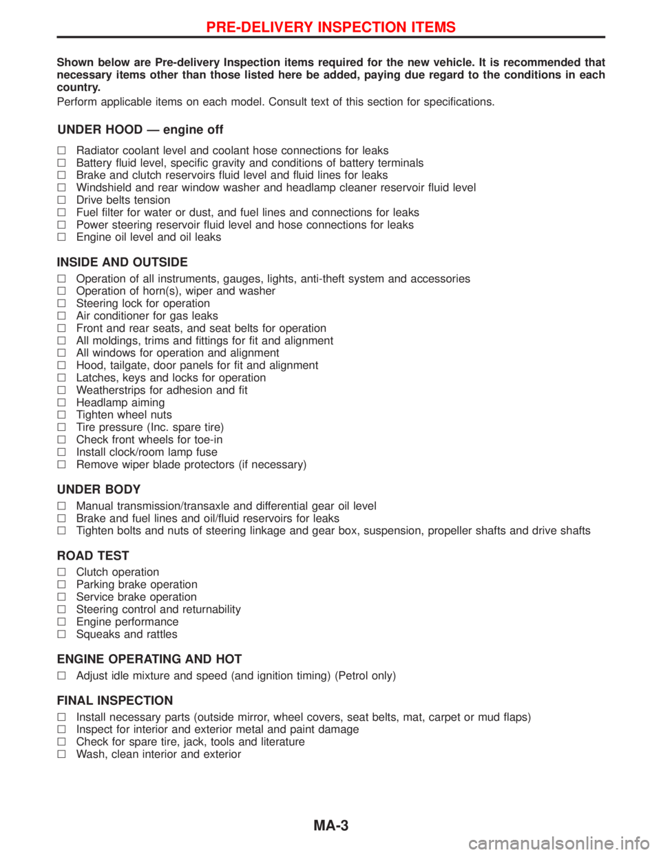
Shown below are Pre-delivery Inspection items required for the new vehicle. It is recommended that
necessary items other than those listed here be added, paying due regard to the conditions in each
country.
Perform applicable items on each model. Consult text of this section for specifications.
UNDER HOOD Ð engine off
lRadiator coolant level and coolant hose connections for leaks
lBattery fluid level, specific gravity and conditions of battery terminals
lBrake and clutch reservoirs fluid level and fluid lines for leaks
lWindshield and rear window washer and headlamp cleaner reservoir fluid level
lDrive belts tension
lFuel filter for water or dust, and fuel lines and connections for leaks
lPower steering reservoir fluid level and hose connections for leaks
lEngine oil level and oil leaks
INSIDE AND OUTSIDE
lOperation of all instruments, gauges, lights, anti-theft system and accessories
lOperation of horn(s), wiper and washer
lSteering lock for operation
lAir conditioner for gas leaks
lFront and rear seats, and seat belts for operation
lAll moldings, trims and fittings for fit and alignment
lAll windows for operation and alignment
lHood, tailgate, door panels for fit and alignment
lLatches, keys and locks for operation
lWeatherstrips for adhesion and fit
lHeadlamp aiming
lTighten wheel nuts
lTire pressure (Inc. spare tire)
lCheck front wheels for toe-in
lInstall clock/room lamp fuse
lRemove wiper blade protectors (if necessary)
UNDER BODY
lManual transmission/transaxle and differential gear oil level
lBrake and fuel lines and oil/fluid reservoirs for leaks
lTighten bolts and nuts of steering linkage and gear box, suspension, propeller shafts and drive shafts
ROAD TEST
lClutch operation
lParking brake operation
lService brake operation
lSteering control and returnability
lEngine performance
lSqueaks and rattles
ENGINE OPERATING AND HOT
lAdjust idle mixture and speed (and ignition timing) (Petrol only)
FINAL INSPECTION
lInstall necessary parts (outside mirror, wheel covers, seat belts, mat, carpet or mud flaps)
lInspect for interior and exterior metal and paint damage
lCheck for spare tire, jack, tools and literature
lWash, clean interior and exterior
PRE-DELIVERY INSPECTION ITEMS
MA-3
Page 1463 of 1767
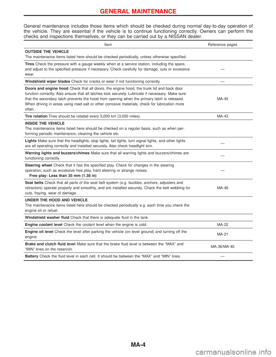
General maintenance includes those items which should be checked during normal day-to-day operation of
the vehicle. They are essential if the vehicle is to continue functioning correctly. Owners can perform the
checks and inspections themselves, or they can be carried out by a NISSAN dealer.
Item Reference pages
OUTSIDE THE VEHICLE
The maintenance items listed here should be checked periodically, unless otherwise specified.
TiresCheck the pressure with a gauge weekly when at a service station, including the spare,
and adjust to the specified pressure if necessary. Check carefully for damage, cuts or excessive
wear.Ð
Windshield wiper bladesCheck for cracks or wear if not functioning correctly. Ð
Doors and engine hoodCheck that all doors, the engine hood, the trunk lid and back door
function correctly. Also ensure that all latches lock securely. Lubricate if necessary. Make sure
that the secondary latch prevents the hood from opening when the primary latch is released.
When driving in areas using road salt or other corrosive materials, check for lubrication more
often.MA-45
Tire rotationTires should be rotated every 5,000 km (3,000 miles). MA-43
INSIDE THE VEHICLE
The maintenance items listed here should be checked on a regular basis, such as when per-
forming periodic maintenance, cleaning the vehicle etc.
LightsMake sure that the headlights, stop lights, tail lights, turn signal lights, and other lights
are all operating correctly and installed securely. Also check headlight aim.Ð
Warning lights and buzzers/chimesMake sure that all warning lights and buzzers/chimes are
functioning correctly.Ð
Steering wheelCheck that it has the specified play. Check for changes in the steering
operation, such as excessive free play, hard steering or strange noises.
Free play: Less than 35 mm (1.38 in)Ð
Seat beltsCheck that all parts of the seat belt system (e.g. buckles, anchors, adjusters and
retractors) operate properly and smoothly, and are installed securely. Check the belt webbing for
cuts, fraying, wear of damage.MA-46
UNDER THE HOOD AND VEHICLE
The maintenance items listed here should be checked periodically e.g. each time you check the
engine oil or refuel.
Windshield washer fluidCheck that there is adequate fluid in the tank.
Engine coolant levelCheck the coolant level when the engine is cold. MA-22
Engine oil levelCheck the level after parking the vehicle (on level ground) and turning off the
engine.MA-21
Brake and clutch fluid levelMake sure that the brake fluid level is between the ªMAXº and
ªMINº lines on the reservoir.MA-36/MA-40
BatteryCheck the fluid level in each cell. It should be between the ªMAXº and ªMINº lines. Ð
GENERAL MAINTENANCE
MA-4
Page 1481 of 1767
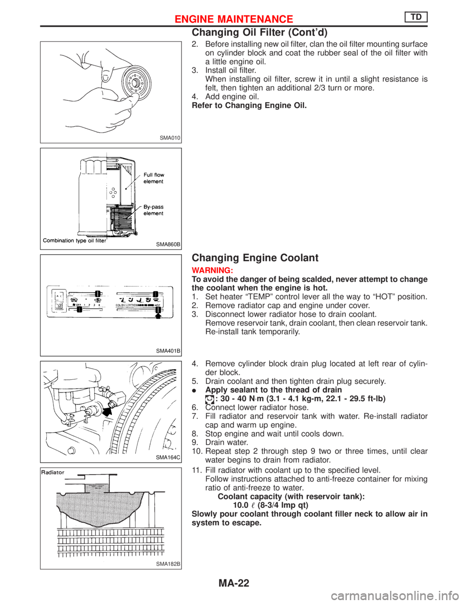
2. Before installing new oil filter, clan the oil filter mounting surface
on cylinder block and coat the rubber seal of the oil filter with
a little engine oil.
3. Install oil filter.
When installing oil filter, screw it in until a slight resistance is
felt, then tighten an additional 2/3 turn or more.
4. Add engine oil.
Refer to Changing Engine Oil.
Changing Engine Coolant
WARNING:
To avoid the danger of being scalded, never attempt to change
the coolant when the engine is hot.
1. Set heater ªTEMPº control lever all the way to ªHOTº position.
2. Remove radiator cap and engine under cover.
3. Disconnect lower radiator hose to drain coolant.
Remove reservoir tank, drain coolant, then clean reservoir tank.
Re-install tank temporarily.
4. Remove cylinder block drain plug located at left rear of cylin-
der block.
5. Drain coolant and then tighten drain plug securely.
IApply sealant to the thread of drain
:30-40N×m (3.1 - 4.1 kg-m, 22.1 - 29.5 ft-lb)
6. Connect lower radiator hose.
7. Fill radiator and reservoir tank with water. Re-install radiator
cap and warm up engine.
8. Stop engine and wait until cools down.
9. Drain water.
10. Repeat step 2 through step 9 two or three times, until clear
water begins to drain from radiator.
11. Fill radiator with coolant up to the specified level.
Follow instructions attached to anti-freeze container for mixing
ratio of anti-freeze to water.
Coolant capacity (with reservoir tank):
10.0(8-3/4 Imp qt)
Slowly pour coolant through coolant filler neck to allow air in
system to escape.
SMA010
SMA860B
SMA401B
SMA164C
SMA182B
ENGINE MAINTENANCETD
Changing Oil Filter (Cont'd)
MA-22