Page 1716 of 1767

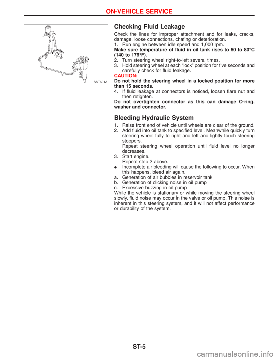
Checking Fluid Leakage
Check the lines for improper attachment and for leaks, cracks,
damage, loose connections, chafing or deterioration.
1. Run engine between idle speed and 1,000 rpm.
Make sure temperature of fluid in oil tank rises to 60 to 80ÉC
(140 to 176ÉF).
2. Turn steering wheel right-to-left several times.
3. Hold steering wheel at each ªlockº position for five seconds and
carefully check for fluid leakage.
CAUTION:
Do not hold the steering wheel in a locked position for more
than 15 seconds.
4. If fluid leakage at connectors is noticed, loosen flare nut and
then retighten.
Do not overtighten connector as this can damage O-ring,
washer and connector.
Bleeding Hydraulic System
1. Raise front end of vehicle until wheels are clear of the ground.
2. Add fluid into oil tank to specified level. Meanwhile quickly turn
steering wheel fully to right and left and lightly touch steering
stoppers.
Repeat steering wheel operation until fluid level no longer
decreases.
3. Start engine.
Repeat step 2 above.
IIncomplete air bleeding will cause the following to occur. When
this happens, bleed air again.
a. Generation of air bubbles in reservoir tank
b. Generation of clicking noise in oil pump
c. Excessive buzzing in oil pump
While the vehicle is stationary or while moving the steering wheel
slowly, fluid noise may occur in the valve or oil pump. This noise is
inherent in this steering system, and it will not affect performance
or durability of the system.
SST621A
ON-VEHICLE SERVICE
ST-5
Page 1722 of 1767

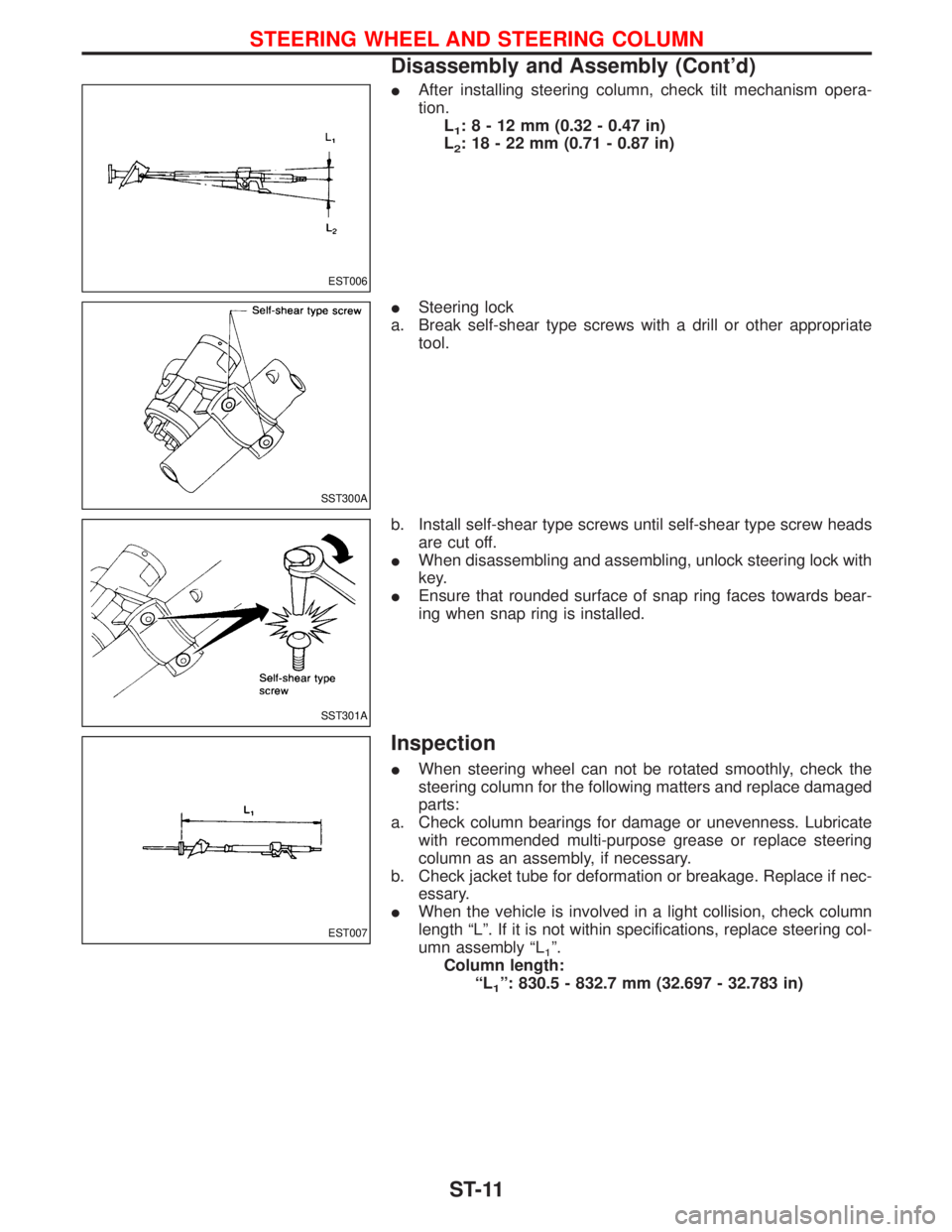
IAfter installing steering column, check tilt mechanism opera-
tion.
L
1:8-12mm(0.32 - 0.47 in)
L
2: 18 - 22 mm (0.71 - 0.87 in)
ISteering lock
a. Break self-shear type screws with a drill or other appropriate
tool.
b. Install self-shear type screws until self-shear type screw heads
are cut off.
IWhen disassembling and assembling, unlock steering lock with
key.
IEnsure that rounded surface of snap ring faces towards bear-
ing when snap ring is installed.
Inspection
IWhen steering wheel can not be rotated smoothly, check the
steering column for the following matters and replace damaged
parts:
a. Check column bearings for damage or unevenness. Lubricate
with recommended multi-purpose grease or replace steering
column as an assembly, if necessary.
b. Check jacket tube for deformation or breakage. Replace if nec-
essary.
IWhen the vehicle is involved in a light collision, check column
length ªLº. If it is not within specifications, replace steering col-
umn assembly ªL
1º.
Column length:
ªL
1º: 830.5 - 832.7 mm (32.697 - 32.783 in)
EST006
SST300A
SST301A
EST007
STEERING WHEEL AND STEERING COLUMN
Disassembly and Assembly (Cont'd)
ST-11
Page 1748 of 1767
d. Remove 2-4 shift rod.
e. Remove L & H shift rod and fork assembly with coupling sleeve.
f. Remove needle bearing from main gear.
g. Remove bolts securing front case cover and then remove case.
h. Remove counter gear by tapping lightly.
SMT283A
SMT284A
SMT286A
SMT287A
SMT759A
DISASSEMBLY
TF-15
Page 1749 of 1767
i. Remove main gear by tapping lightly.
SMT288A
DISASSEMBLY
TF-16
Page 1759 of 1767
1. Assemble front case.
a. Install main gear assembly by tapping lightly.
b. Apply sealant to the mating surface and bolts of front case
cover and install it on front case.
IThese ten bolts should be coated with sealant.
Tightening torque
q
A: 16-21N×m
(1.6 - 2.1 kg-m, 12 - 15 ft-lb)
q
B: 19-24N×m
(1.9 - 2.4 kg-m, 14 - 17 ft-lb)
c. Apply gear oil to needle bearing and install it into main gear.
d. Install counter gear assembly by tapping lightly.
e. Install cross shaft and inner shift lever.
When replacing cross shaft, outer shift lever of lock pin of
outer shift lever, replace them as a set.
SMT323A
YMT027
SMT326A
SMT327A
SMT798A
ASSEMBLY
TF-26
Page 1761 of 1767
2. Select counter gear rear bearing shim.
Counter gear end play:
0 - 0.2 mm (0 - 0.008 in)
a. Measure distance ªAº between upper surface of counter gear
rear bearing and mating surface of front case.
b. Select suitable shim using chart below.
Distance ªAº mm (in)Suitable shim
Thickness mm (in) Part number
32.65 - 32.55
(1.2854 - 1.2815)Not necessary
32.55 - 32.45
(1.2815 - 1.2776)0.1 (0.004) 33112-C6900
32.45 - 32.35
(1.2776 - 1.2736)0.2 (0.008) 33112-C6901
32.35 - 32.25
(1.2736 - 1.2697)0.3 (0.012) 33112-C6902
32.25 - 32.15
(1.2697 - 1.2657)0.4 (0.016) 33112-C6903
32.15 - 32.05
(1.2657 - 1.2618)0.5 (0.020) 33112-33G00
32.05 - 31.95
(1.2618 - 1.2579)0.6 (0.024) 33112-33G01
3. Place suitable shim on counter gear rear bearing with grease.
4. Apply gear oil to each part in front case.
5. Assemble center case assembly.
a. Install mainshaft on center case by tapping lightly.
Apply gear oil to mainshaft front bearing.
SMT335A
SMT334A
SMT336A
SMT406A
ASSEMBLY
TF-28
Page 1762 of 1767
b. Install bearing retainer.
c. Put drive chain onto the front drive sprocket and front drive
shaft, and then put them in center case.
d. Install front drive shaft by tapping lightly.
e. Apply gear oil to needle bearings and install them into front
drive sprocket.
These needle bearings will be installed more easily if front
drive sprocket is rotated while installing them.
SMT407A
SMT408A
SMT409A
SMT410A
SMT411A
ASSEMBLY
TF-29