Page 1593 of 1767
6. Install pinion mate gears and pinion shaft to differential case B.
7. Install side gear to pinion mate gears.
8. Install each disc and plate.
Use same procedures as outlined in steps 1. through 4. above.
9. Install differential case A.
Position differential cases A and B by correctly aligning marks
stamped on cases.
10. Tighten differential case bolts.
:64-69N×m (6.5 - 7.0 kg-m, 47 - 51 ft-lb)
11. Place ring gear on differential case and install new lock straps
and bolts.
Tighten bolts in a criss-cross fashion, lightly tapping bolt head
with a hammer.
Then bend up lock straps to lock the bolts in place.
12. Install side bearing inner cone.
13. Check differential torque.
SPD426
SPD429
SPD430
SPD288
LIMITED SLIP DIFFERENTIAL (H233B)
Assembly (Cont'd)
PD-48
Page 1600 of 1767
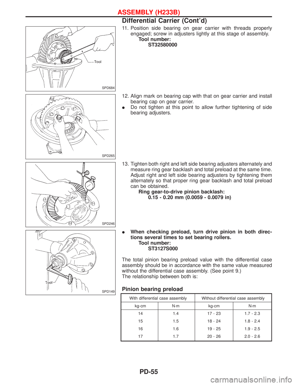
11. Position side bearing on gear carrier with threads properly
engaged; screw in adjusters lightly at this stage of assembly.
Tool number:
ST32580000
12. Align mark on bearing cap with that on gear carrier and install
bearing cap on gear carrier.
IDo not tighten at this point to allow further tightening of side
bearing adjusters.
13. Tighten both right and left side bearing adjusters alternately and
measure ring gear backlash and total preload at the same time.
Adjust right and left side bearing adjusters by tightening them
alternately so that proper ring gear backlash and total preload
can be obtained.
Ring gear-to-drive pinion backlash:
0.15 - 0.20 mm (0.0059 - 0.0079 in)
IWhen checking preload, turn drive pinion in both direc-
tions several times to set bearing rollers.
Tool number:
ST3127S000
The total pinion bearing preload value with the differential case
assembly should be in accordance with the same value measured
without the differential case assembly. (See point 9.)
The relationship between both is:
Pinion bearing preload
With differential case assembly Without differential case assembly
kg-cm N×m kg-cm N×m
14 1.4 17 - 23 1.7 - 2.3
15 1.5 18 - 24 1.8 - 2.4
16 1.6 19 - 25 1.9 - 2.5
17 1.7 20 - 26 2.0 - 2.6
SPD684
SPD265
SPD246
SPD149
ASSEMBLY (H233B)
Differential Carrier (Cont'd)
PD-55
Page 1602 of 1767
Propeller Shaft
GENERAL SPECIFICATIONS
Unit: mm (in)
MODEL ALL H/T WAGON
Portion Front Rear
Propeller shaft
model0F71H 2S80B
Number of joints 2
Coupling
method with
transmissionFlange type Sleeve type
Types of journal
bearingsSolid type (dis-
assembly type)Solid type
Shaft length
(Spider to spi-
der) mm (in)542 (21.34) 725 (28.54) 925 (36.42)
Shaft outer
diameter mm (in)65 (2.56) 65 (2.56)
INSPECTION AND ADJUSTMENT
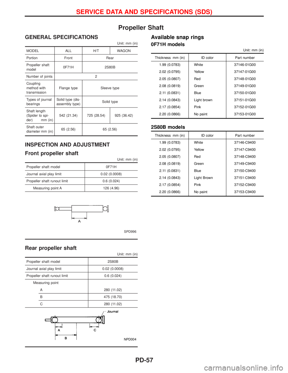
Front propeller shaft
Unit: mm (in)
Propeller shaft model 0F71H
Journal axial play limit 0.02 (0.0008)
Propeller shaft runout limit 0.6 (0.024)
Measuring point A 126 (4.96)
SPD996
Rear propeller shaft
Unit: mm (in)
Propeller shaft model 2S80B
Journal axial play limit 0.02 (0.0008)
Propeller shaft runout limit 0.6 (0.024)
Measuring point
A 280 (11.02)
B 475 (18.70)
C 280 (11.02)
NPD004
Available snap rings
0F71H models
Unit: mm (in)
Thickness mm (in) ID color Part number
1.99 (0.0783) White 37146-01G00
2.02 (0.0795) Yellow 37147-01G00
2.05 (0.0807) Red 37148-01G00
2.08 (0.0819) Green 37149-01G00
2.11 (0.0831) Blue 37150-01G00
2.14 (0.0843) Light brown 37151-01G00
2.17 (0.0854) Pink 37152-01G00
2.20 (0.0866) No paint 37153-01G00
2S80B models
Thickness mm (in) ID color Part number
1.99 (0.0783) White 37146-C9400
2.02 (0.0795) Yellow 37147-C9400
2.05 (0.0807) Red 37148-C9400
2.08 (0.0819) Green 37149-C9400
2.11 (0.0831) Blue 37150-C9400
2.14 (0.0843) Light Brown 37151-C9400
2.17 (0.0854) Pink 37152-C9400
2.20 (0.0866) No paint 37153-C9400
SERVICE DATA AND SPECIFICATIONS (SDS)
PD-57
Page 1642 of 1767
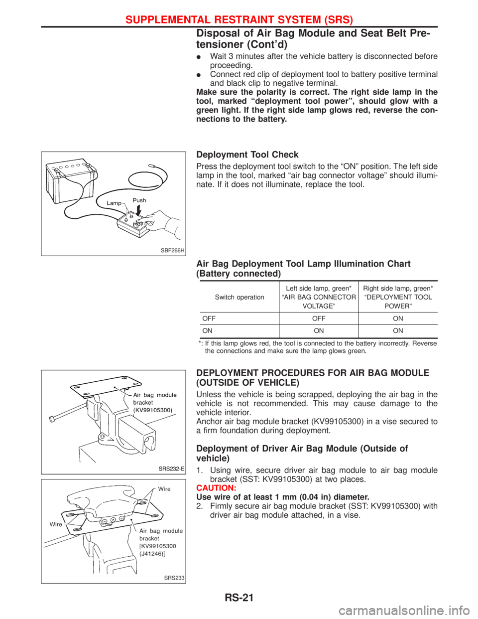
IWait 3 minutes after the vehicle battery is disconnected before
proceeding.
IConnect red clip of deployment tool to battery positive terminal
and black clip to negative terminal.
Make sure the polarity is correct. The right side lamp in the
tool, marked ªdeployment tool powerº, should glow with a
green light. If the right side lamp glows red, reverse the con-
nections to the battery.
Deployment Tool Check
Press the deployment tool switch to the ªONº position. The left side
lamp in the tool, marked ªair bag connector voltageº should illumi-
nate. If it does not illuminate, replace the tool.
Air Bag Deployment Tool Lamp Illumination Chart
(Battery connected)
Switch operationLeft side lamp, green*
ªAIR BAG CONNECTOR
VOLTAGEºRight side lamp, green*
ªDEPLOYMENT TOOL
POWERº
OFF OFF ON
ON ON ON
*: If this lamp glows red, the tool is connected to the battery incorrectly. Reverse
the connections and make sure the lamp glows green.
DEPLOYMENT PROCEDURES FOR AIR BAG MODULE
(OUTSIDE OF VEHICLE)
Unless the vehicle is being scrapped, deploying the air bag in the
vehicle is not recommended. This may cause damage to the
vehicle interior.
Anchor air bag module bracket (KV99105300) in a vise secured to
a firm foundation during deployment.
Deployment of Driver Air Bag Module (Outside of
vehicle)
1. Using wire, secure driver air bag module to air bag module
bracket (SST: KV99105300) at two places.
CAUTION:
Use wire of at least 1 mm (0.04 in) diameter.
2. Firmly secure air bag module bracket (SST: KV99105300) with
driver air bag module attached, in a vise.
SBF266H
SRS232-E
SRS233
SUPPLEMENTAL RESTRAINT SYSTEM (SRS)
Disposal of Air Bag Module and Seat Belt Pre-
tensioner (Cont'd)
RS-21
Page 1648 of 1767
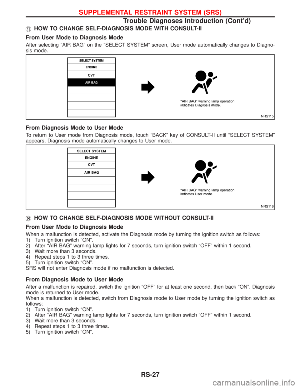
HOW TO CHANGE SELF-DIAGNOSIS MODE WITH CONSULT-II
From User Mode to Diagnosis Mode
After selecting ªAIR BAGº on the ªSELECT SYSTEMº screen, User mode automatically changes to Diagno-
sis mode.
From Diagnosis Mode to User Mode
To return to User mode from Diagnosis mode, touch ªBACKº key of CONSULT-II until ªSELECT SYSTEMº
appears, Diagnosis mode automatically changes to User mode.
HOW TO CHANGE SELF-DIAGNOSIS MODE WITHOUT CONSULT-II
From User Mode to Diagnosis Mode
When a malfunction is detected, activate the Diagnosis mode by turning the ignition switch as follows:
1) Turn ignition switch ªONº.
2) After ªAIR BAGº warning lamp lights for 7 seconds, turn ignition switch ªOFFº within 1 second.
3) Wait more than 3 seconds.
4) Repeat steps 1 to 3 three times.
5) Turn ignition switch ªONº.
SRS will not enter Diagnosis mode if no malfunction is detected.
From Diagnosis Mode to User Mode
After a malfunction is repaired, switch the ignition ªOFFº for at least one second, then back ªONº. Diagnosis
mode is returned to User mode.
When a malfunction is detected, switch from Diagnosis mode to User mode by turning the ignition switch as
follows:
1) Turn ignition switch ªONº.
2) After ªAIR BAGº warning lamp lights for 7 seconds, turn ignition switch ªOFFº within 1 second.
3) Wait more than 3 seconds.
4) Repeat steps 1 to 3 three times.
5) Turn ignition switch ªONº.
NRS115
NRS116
SUPPLEMENTAL RESTRAINT SYSTEM (SRS)
Trouble Diagnoses Introduction (Cont'd)
RS-27
Page 1667 of 1767
![NISSAN TERRANO 2002 Service Repair Manual Diagnostic item Explanation Repair order
PRE-TEN FRONT RH
[OPEN/VB-SHORT]IThe circuit for front RH seat belt pre-
tensioner is open or shorted to a power
supply circuit.1. Visually check the wiring ha NISSAN TERRANO 2002 Service Repair Manual Diagnostic item Explanation Repair order
PRE-TEN FRONT RH
[OPEN/VB-SHORT]IThe circuit for front RH seat belt pre-
tensioner is open or shorted to a power
supply circuit.1. Visually check the wiring ha](/manual-img/5/57393/w960_57393-1666.png)
Diagnostic item Explanation Repair order
PRE-TEN FRONT RH
[OPEN/VB-SHORT]IThe circuit for front RH seat belt pre-
tensioner is open or shorted to a power
supply circuit.1. Visually check the wiring harness con-
nections.
2. Replace the harness if it has visible
damage.
3. If the harness check is OK, replace the
diagnosis sensor unit and front RH seat
belt. (Before disposing of the front RH
seat belt pre-tensioner, if must be
deployed.) PRE-TEN FRONT RH
[GND-SHORT]IThe circuit for front RH seat belt pre-
tensioner is shorted to ground.
CONTROL UNITIDiagnosis sensor unit is malfunctioning. 1. Visually check the wiring harness con-
nection.
2. Replace the harness if it has visible
damage.
3. If the harness check is OK, replace the
diagnosis sensor unit.
* Follow the procedures in numerical order when repairing malfunctioning parts, then make the final system check.
Trouble Diagnoses without CONSULT-II
DIAGNOSTIC PROCEDURE 6
Inspecting SRS malfunctioning parts by using ªAIR BAGº
warning lamp Ð Diagnosis mode
NOTE:
SRS will not enter Diagnosis mode if no malfunction is
detected in User mode.
1. Turn ignition switch ªONº.
2. After ªAIR BAGº warning lamp lights for 7 seconds, turn ignition
switch ªOFFº within 1 second.
3. Wait more than 3 seconds.
4. Repeat steps 1 to 3 three times.
5. Turn ignition switch ªONº.
SRS is now in Diagnosis mode.
6. ªAIR BAGº warning lamp operates in Diagnosis mode as fol-
lows:
NOTE:
If SRS does not enter Diagnosis mode even though malfunc-
tion is detected in User mode, check the battery voltage.
If the battery voltage is less than 9V, charge the battery. Then
go to DIAGNOSTIC PROCEDURE 7, page RS-51.
If the battery voltage is OK, replace the diagnosis sensor unit.
SRS800
SUPPLEMENTAL RESTRAINT SYSTEM (SRS)
Trouble Diagnoses with CONSULT-II (Cont'd)
RS-46
Page 1674 of 1767
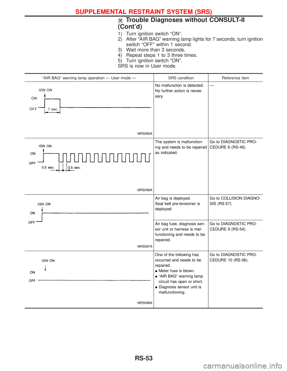
1) Turn ignition switch ªONº.
2) After ªAIR BAGº warning lamp lights for 7 seconds, turn ignition
switch ªOFFº within 1 second.
3) Wait more than 3 seconds.
4) Repeat steps 1 to 3 three times.
5) Turn ignition switch ªONº.
SRS is now in User mode.
ªAIR BAGº warning lamp operation Ð User mode Ð SRS condition Reference item
MRS095A
No malfunction is detected.
No further action is neces-
sary.Ð
MRS096A
The system is malfunction-
ing and needs to be repaired
as indicated.Go to DIAGNOSTIC PRO-
CEDURE 6 (RS-46).
MRS097A
Air bag is deployed.
Seat belt pre-tensioner is
deployed.Go to COLLISION DIAGNO-
SIS (RS-57).
Air bag fuse, diagnosis sen-
sor unit or harness is mal-
functioning and needs to be
repaired.Go to DIAGNOSTIC PRO-
CEDURE 9 (RS-54).
MRS098A
One of the following has
occurred and needs to be
repaired.
IMeter fuse is blown.
IªAIR BAGº warning lamp
circuit has open or short.
IDiagnosis sensor unit is
malfunctioning.Go to DIAGNOSTIC PRO-
CEDURE 10 (RS-56).
SUPPLEMENTAL RESTRAINT SYSTEM (SRS)
Trouble Diagnoses without CONSULT-II
(Cont'd)
RS-53
Page 1702 of 1767
Armature Check
1. Continuity test (between two segments side by side).
INo continuity ... Replace.
2. Insulation test (between each commutator bar and shaft).
IContinuity exists ... Replace.
3. Check commutator surface.
IRough ... Sand lightly with No. 500-600 emery paper.
4. Check diameter of commutator.
Commutator minimum diameter:
Refer to SDS (SC-30).
ILess than specified value ... Replace.
SEL625B
SEL104E
SEL020Z
SEL021Z
STARTING SYSTEM
SC-21