Page 1483 of 1767

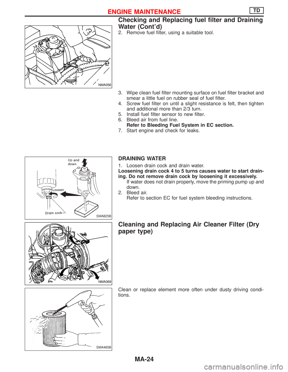
2. Remove fuel filter, using a suitable tool.
3. Wipe clean fuel filter mounting surface on fuel filter bracket and
smear a little fuel on rubber seal of fuel filter.
4. Screw fuel filter on until a slight resistance is felt, then tighten
and additional more than 2/3 turn.
5. Install fuel filter sensor to new filter.
6. Bleed air from fuel line.
Refer to Bleeding Fuel System in EC section.
7. Start engine and check for leaks.
DRAINING WATER
1. Loosen drain cock and drain water.
Loosening drain cock 4 to 5 turns causes water to start drain-
ing. Do not remove drain cock by loosening it excessively.
If water does not drain properly, move the priming pump up and
down.
2. Bleed air.
Refer to section EC for fuel system bleeding instructions.
Cleaning and Replacing Air Cleaner Filter (Dry
paper type)
Clean or replace element more often under dusty driving condi-
tions.
NMA056
SMA825B
NMA069
SMA485B
ENGINE MAINTENANCETD
Checking and Replacing fuel filter and Draining
Water (Cont'd)
MA-24
Page 1485 of 1767

Checking Idle Speed
Preparation
1. Make sure that injection timing is correct.
2. Make sure that injection nozzle are in good condition.
3. Make sure that the following parts are in good condition.
IAir cleaner clogging
IGlow system
IEngine oil and coolant levels
IValve clearance
IAir intake system (Oil filler cap, oil level gauge, etc.)
4. Set shift lever in ªNeutralº position. Engage parking brake and
lock both front and rear wheels with wheel chocks.
5. Turn off air conditioner, lights and accessories.
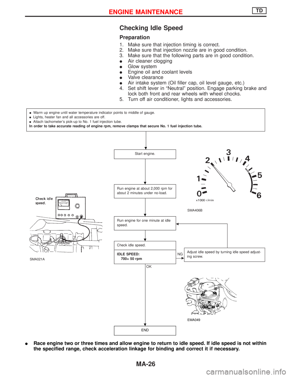
IWarm up engine until water temperature indicator points to middle of gauge.
ILights, heater fan and all accessories are off.
IAttach tachometer's pick-up to No. 1 fuel injection tube.
In order to take accurate reading of engine rpm, remove clamps that secure No. 1 fuel injection tube.
Start engine.
SMA406B
SMA021A
Run engine at about 2,000 rpm for
about 2 minutes under no-load.
Run engine for one minute at idle
speed.F
Check idle speed.
----------------------------------------------------------------------------------------------------------------------------------------------------------------------------------------------------------------------------------
IDLE SPEED:
700+ 50 rpm
OK
ENGAdjust idle speed by turning idle speed adjust-
ing screw.
EMA049
END
IRace engine two or three times and allow engine to return to idle speed. If idle speed is not within
the specified range, check acceleration linkage for binding and correct it if necessary.
H
H
H
H
H
ENGINE MAINTENANCETD
MA-26
Page 1493 of 1767

4. Wipe clean fuel filter mounting surface on fuel filter bracket and
smear a little fuel on rubber seal of fuel filter.
5. Screw fuel filter on until a slight resistance is felt, then tighten
an additional more than 2/3 or a turn.
6. Install fuel filter sensor to new fuel filter. (Type A)
7. Bleed air from fuel filter.
Refer to ªAir Bleedingº in EC section.
8. Start engine and check for leaks.
DRAINING WATER
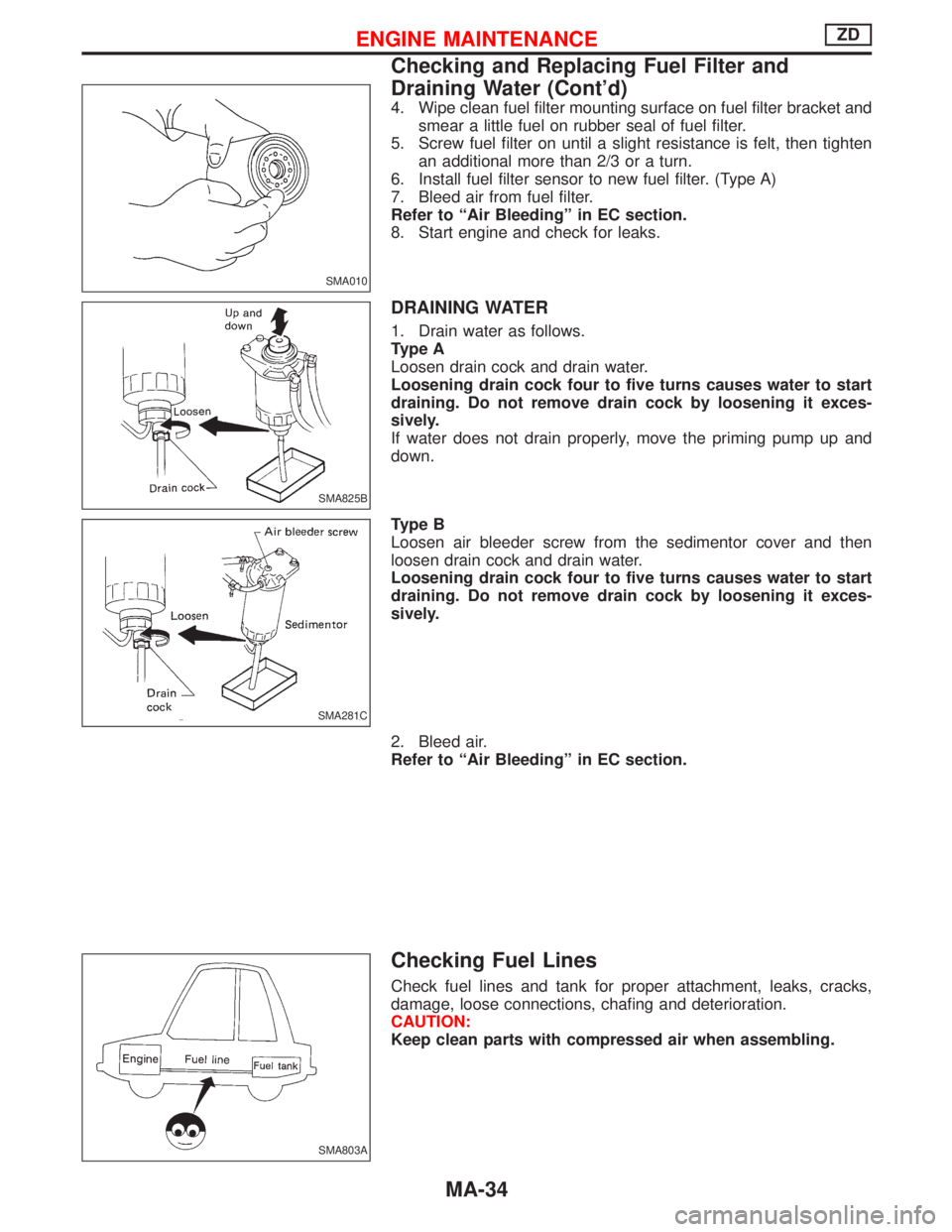
1. Drain water as follows.
Type A
Loosen drain cock and drain water.
Loosening drain cock four to five turns causes water to start
draining. Do not remove drain cock by loosening it exces-
sively.
If water does not drain properly, move the priming pump up and
down.
Type B
Loosen air bleeder screw from the sedimentor cover and then
loosen drain cock and drain water.
Loosening drain cock four to five turns causes water to start
draining. Do not remove drain cock by loosening it exces-
sively.
2. Bleed air.
Refer to ªAir Bleedingº in EC section.
Checking Fuel Lines
Check fuel lines and tank for proper attachment, leaks, cracks,
damage, loose connections, chafing and deterioration.
CAUTION:
Keep clean parts with compressed air when assembling.
SMA010
SMA825B
SMA281C
SMA803A
ENGINE MAINTENANCEZD
Checking and Replacing Fuel Filter and
Draining Water (Cont'd)
MA-34
Page 1518 of 1767

IRaise the unit with a hoist.
IPosition the transmission assembly on a portable jack and
secure it with a suitable tool.
Lift the assembly until the gearbox input shaft faces its hous-
ing.
Move the assembly towards the engine. The assembly must be
rotated slightly so that the starter motor housing clears the
projection on the companion floor. Insert input shaft into its
housing (slightly raising the rear of the transfer box may facili-
tate the introduction of the shaft into its housing).
ITighten the screws securing the gearbox to the engine.
:39-49N×m (4.0 - 5.0 kg-m, 29 - 36 ft-lb)
IConnect the electrical wiring. Secure with the respective clips.
IFit the RPM-sensor to the transmission upper side.
IFit the exhaust pipe support bracket to the transfer box.
:13-16N×m (1.3 - 1.6 kg-m,9-12ft-lb)
IFit the starter motor. Secure the earth wire to the starter motor
lower screw.
:31-41N×m (3.2 - 4.2 kg-m, 23 - 30 ft-lb)
IFit the clutch slave cylinder.
:30-40N×m (3.1 - 4.1 kg-m, 22 - 30 ft-lb)
IInstall fourth crossmember (Note the ªfrontº mark).
Crossmember fixing bolts to chassis:
:41-52N×m (4.2 - 5.3 kg-m, 30 - 38 ft-lb)
Crossmember fixing bolts to transmission:
:68-87N×m (6.9 - 8.9 kg-m, 50 - 64 ft-lb)
ITake away the portable jack holding boxes assembly.
IInstall fifth crossmember.
:59-78N×m (6.0 - 8.0 kg-m, 43 - 58 ft-lb)
IInstall third crossmember.
: Screws: 41 - 52 N×m (4.2 - 5.3 kg-m,
30 - 38 ft-lb)
Nuts: 68 - 87 N×m (6.9 - 8.9 kg-m,
50 - 64 ft-lb)
IInstall torsion bar springs. Ð Refer to FA section.
IInstall front and rear propeller shafts. Ð Refer to PD section.
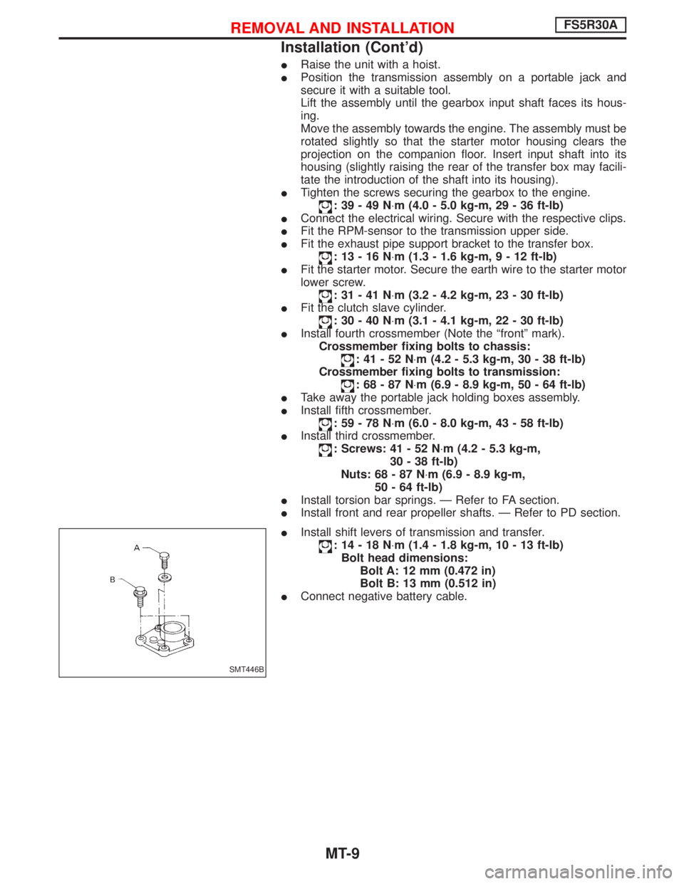
IInstall shift levers of transmission and transfer.
:14-18N×m (1.4 - 1.8 kg-m, 10 - 13 ft-lb)
Bolt head dimensions:
Bolt A: 12 mm (0.472 in)
Bolt B: 13 mm (0.512 in)
IConnect negative battery cable.
SMT446B
REMOVAL AND INSTALLATIONFS5R30A
Installation (Cont'd)
MT-9
Page 1523 of 1767
Case Components
1. Remove check ball plug, check spring and check ball. Then
remove interlock stopper.
If interlock assembly is removed as a unit, the check ball can
fall into transmission case.
2. Remove control housing, return spring and check ball.
3. Drive out retaining pin from striking arm.
4. Remove OD gear case together with striking arm by tapping
lightly.
SMT366A
SMT438B
SMT439B
SMT440B
SMT444B
DISASSEMBLY
MT-14
Page 1524 of 1767
5. Remove front cover and gasket.
6. Remove stopper ring and main drive bearing snap ring.
7. Remove transmission case by tapping lightly.
8. Remove front cover oil seal.
Shift Control Components
1. Mount adapter plate on vise.
2. Remove OD & reverse fork rod.
SMT441B
SMT371A
SMT372A
SMT392A
SMT373A
DISASSEMBLY
Case Components (Cont'd)
MT-15
Page 1553 of 1767
2. Remove snap ring.
3. Remove pushed out journal bearing by lightly tapping yoke with
a hammer, taking care not to damage journal and yoke hole.
4. Remove bearing at opposite side in above operation.
Put marks on disassembled parts so that they can be rein-
stalled in their original positions from which they were
removed.
Assembly
JOURNAL
1. Assemble journal bearing. Apply recommended multi-purpose
grease on bearing inner surface.
When assembling, be careful that needle bearing does not fall
down.
2. Select snap rings that will provide specified play in axial direc-
tion of journal, and install them. (Refer to PD-57.)
Select snap rings with a difference in thickness at both sides
within 0.06 mm (0.0024 in).
SPD731
SPD732
SPD131
SPD133
SPD134
PROPELLER SHAFT
Disassembly (Cont'd)
PD-8
Page 1574 of 1767
Differential Case
1. Measure clearance between side gear thrust washer and dif-
ferential case.
Clearance between side gear thrust washer and differ-
ential case (A þ B):
0.10 - 0.20 mm (0.0039 - 0.0079 in)
The clearance can be adjusted with side gear thrust washer.
(Refer to PD-57.)
2. Apply gear oil to gear tooth surfaces and thrust surfaces and
check to see the turn properly.
3. Install L.H. and R.H. differential cases.
4. Place differential case on ring gear.
5. Apply locking agent [Locktite (stud lock) or equivalent] to ring
gear bolts, and install them.
Tighten bolts in a criss-cross fashion, lightly tapping bolt head
with a hammer.
6. Press-fit side bearing inner cones on differential case with Tool.
Tool number:
q
AST33230000
q
BST33061000
SPD656
SPD643
SPD746
PD353
ASSEMBLY (R180A)
PD-29