Page 1281 of 1767
3. Remove nuts fixing lower ball joint on lower link.
Support lower link with jack.
4. Remove upper ball joint fixing bolt.
5. Remove shock absorber lower bolt.
6. Remove drive shaft with knuckle.
Cover drive shaft boot with a suitable protector.
7. Separate drive shaft from knuckle by slightly tapping it.
SFA843
SFA842
SFA864
SFA878
SFA879
FRONT AXLE Ð Drive Shaft
Removal (Cont'd)
FA-23
Page 1282 of 1767
Disassembly
FINAL DRIVE SIDE
Ð TS82F type Ð
1. Remove plug seal from slide joint housing by lightly tapping
around slide joint housing.
2. Remove boot bands.
3. Move boot and slide joint housing toward wheel side, and put
matching marks.
4. Pry off snap ring.
5. Detach spider assembly with press.
SFA880
SFA881
SFA963
SFA964
SFA392
FRONT AXLE Ð Drive Shaft
FA-24
Page 1285 of 1767
7. Install new plug seal to slide joint housing by lightly tapping it.
Apply sealant to mating surface of plug seal.
WHEEL SIDE (ZF100)
1. Install new small boot band and boot on drive shaft.
Cover drive shaft serration with tape so as not to damage boot
during installation.
2. Set joint assembly onto drive shaft by lightly tapping it.
Install joint assembly securely, ensuring marks which were
made during disassembly are properly aligned.
3. Pack drive shaft with specified amount of grease.
Specified amount of grease:
100 - 120 g (3.53 - 4.23 oz)
4. Set boot so that is does not swell and deform when its length
is ªLº.
Length ªLº = 96 - 98 mm (3.78 - 3.86 in)
Make sure that boot is properly installed on the drive shaft
groove.
SFA472
SFA800
SFA884
SFA885
YFA011
FRONT AXLE Ð Drive Shaft
Assembly (Cont'd)
FA-27
Page 1300 of 1767

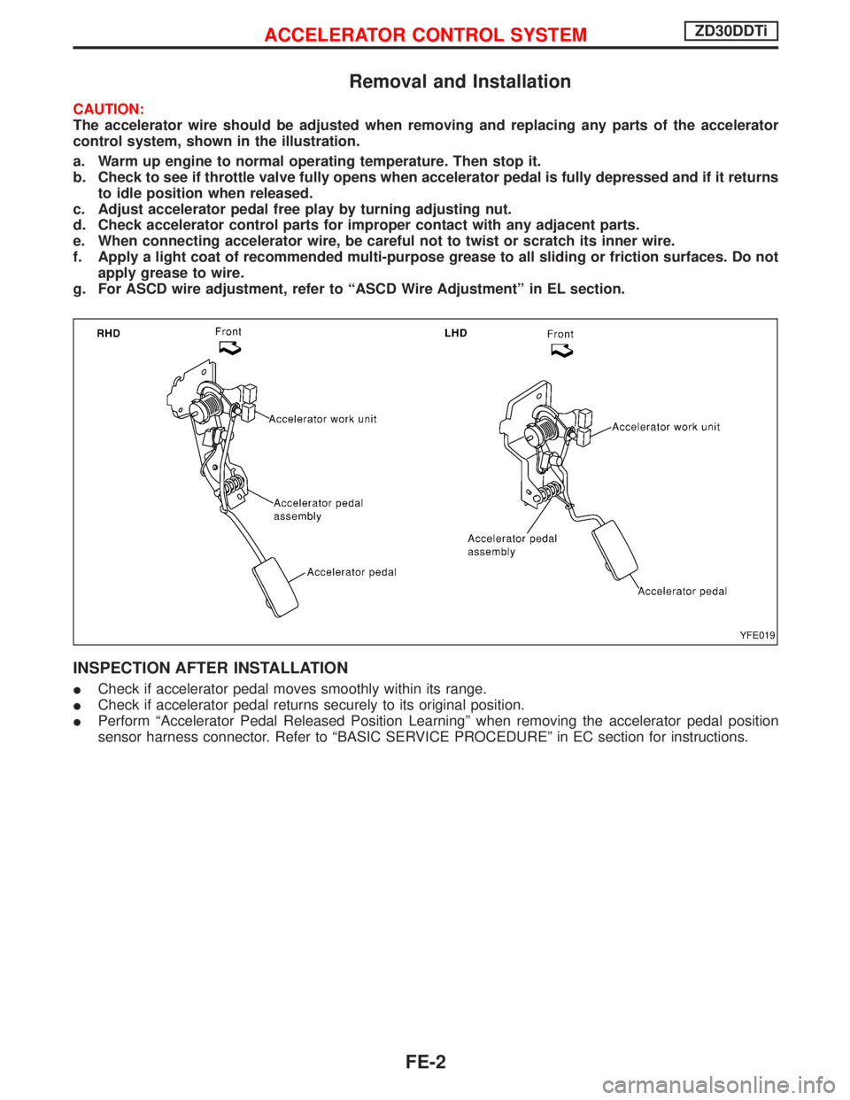
Removal and Installation
CAUTION:
The accelerator wire should be adjusted when removing and replacing any parts of the accelerator
control system, shown in the illustration.
a. Warm up engine to normal operating temperature. Then stop it.
b. Check to see if throttle valve fully opens when accelerator pedal is fully depressed and if it returns
to idle position when released.
c. Adjust accelerator pedal free play by turning adjusting nut.
d. Check accelerator control parts for improper contact with any adjacent parts.
e. When connecting accelerator wire, be careful not to twist or scratch its inner wire.
f. Apply a light coat of recommended multi-purpose grease to all sliding or friction surfaces. Do not
apply grease to wire.
g. For ASCD wire adjustment, refer to ªASCD Wire Adjustmentº in EL section.
INSPECTION AFTER INSTALLATION
ICheck if accelerator pedal moves smoothly within its range.
ICheck if accelerator pedal returns securely to its original position.
IPerform ªAccelerator Pedal Released Position Learningº when removing the accelerator pedal position
sensor harness connector. Refer to ªBASIC SERVICE PROCEDUREº in EC section for instructions.
YFE019
ACCELERATOR CONTROL SYSTEMZD30DDTi
FE-2
Page 1327 of 1767

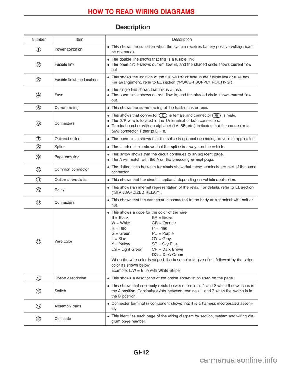
Description
Number Item Description
q1Power conditionIThis shows the condition when the system receives battery positive voltage (can
be operated).
q2Fusible linkIThe double line shows that this is a fusible link.
IThe open circle shows current flow in, and the shaded circle shows current flow
out.
q3Fusible link/fuse locationIThis shows the location of the fusible link or fuse in the fusible link or fuse box.
For arrangement, refer to EL section (ªPOWER SUPPLY ROUTINGº).
q4FuseIThe single line shows that this is a fuse.
IThe open circle shows current flow in, and the shaded circle shows current flow
out.
q5Current ratingIThis shows the current rating of the fusible link or fuse.
q6ConnectorsIThis shows that connector
E3is female and connectorM1is male.
IThe G/R wire is located in the 1A terminal of both connectors.
ITerminal number with an alphabet (1A, 5B, etc.) indicates that the connector is
SMJ connector. Refer to GI-18.
q7Optional spliceIThe open circle shows that the splice is optional depending on vehicle application.
q8SpliceIThe shaded circle shows that the splice is always on the vehicle.
q9Page crossingIThis arrow shows that the circuit continues to an adjacent page.
IThe A will match with the A on the preceding or next page.
q10Common connectorIThe dotted lines between terminals show that these terminals are part of the same
connector.
q11Option abbreviationIThis shows that the circuit is optional depending on vehicle application.
q12RelayIThis shows an internal representation of the relay. For details, refer to EL section
(ªSTANDARDIZED RELAYº).
q13ConnectorsIThis shows that the connector is connected to the body or a terminal with bolt or
nut.
q14Wire colorIThis shows a code for the color of the wire.
B = Black BR = Brown
W = White OR = Orange
R = Red P = Pink
G = Green PU = Purple
L = Blue GY = Gray
Y = Yellow SB = Sky Blue
LG = Light Green CH = Dark Brown
DG = Dark Green
When the wire color is striped, the base color is given first, followed by the stripe
color as shown below:
Example: L/W = Blue with White Stripe
q15Option descriptionIThis shows a description of the option abbreviation used on the page.
q16SwitchIThis shows that continuity exists between terminals 1 and 2 when the switch is in
the A position. Continuity exists between terminals 1 and 3 when the switch is in
the B position.
q17Assembly partsIConnector terminal in component shows that it is a harness incorporated assem-
bly.
q18Cell codeIThis identifies each page of the wiring diagram by section, system and wiring dia-
gram page number.
HOW TO READ WIRING DIAGRAMS
GI-12
Page 1338 of 1767

Incident Simulation Tests
INTRODUCTION
Sometimes the symptom is not present when the vehicle is brought in for service. If possible, re-create the
conditions present at the time of the incident. Doing so may help avoid a No Trouble Found Diagnosis. The
following section illustrates ways to simulate the conditions/environment under which the owner experiences
an electrical incident.
The section is broken into the six following topics:
IVehicle vibration
IHeat sensitive
IFreezing
IWater intrusion
IElectrical load
ICold or hot start up
Get a thorough description of the incident from the customer. It is important for simulating the conditions of
the problem.
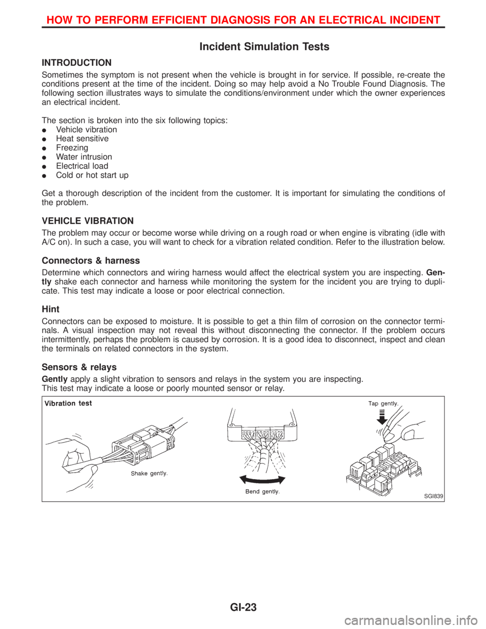
VEHICLE VIBRATION
The problem may occur or become worse while driving on a rough road or when engine is vibrating (idle with
A/C on). In such a case, you will want to check for a vibration related condition. Refer to the illustration below.
Connectors & harness
Determine which connectors and wiring harness would affect the electrical system you are inspecting.Gen-
tlyshake each connector and harness while monitoring the system for the incident you are trying to dupli-
cate. This test may indicate a loose or poor electrical connection.
Hint
Connectors can be exposed to moisture. It is possible to get a thin film of corrosion on the connector termi-
nals. A visual inspection may not reveal this without disconnecting the connector. If the problem occurs
intermittently, perhaps the problem is caused by corrosion. It is a good idea to disconnect, inspect and clean
the terminals on related connectors in the system.
Sensors & relays
Gentlyapply a slight vibration to sensors and relays in the system you are inspecting.
This test may indicate a loose or poorly mounted sensor or relay.
SGI839
HOW TO PERFORM EFFICIENT DIAGNOSIS FOR AN ELECTRICAL INCIDENT
GI-23
Page 1351 of 1767

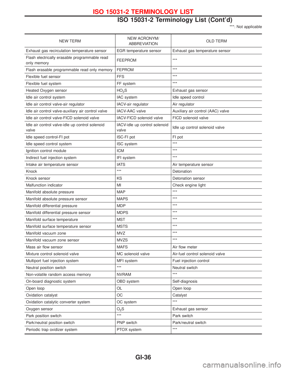
***: Not applicable
NEW TERMNEW ACRONYM/
ABBREVIATIONOLD TERM
Exhaust gas recirculation temperature sensor EGR temperature sensor Exhaust gas temperature sensor
Flash electrically erasable programmable read
only memoryFEEPROM ***
Flash erasable programmable read only memory FEPROM ***
Flexible fuel sensor FFS ***
Flexible fuel system FF system ***
Heated Oxygen sensor HO
2S Exhaust gas sensor
Idle air control system IAC system Idle speed control
Idle air control valve-air regulator IACV-air regulator Air regulator
Idle air control valve-auxiliary air control valve IACV-AAC valve Auxiliary air control (AAC) valve
Idle air control valve-FICD solenoid valve IACV-FICD solenoid valve FICD solenoid valve
Idle air control valve-idle up control solenoid
valveIACV-idle up control solenoid
valveIdle up control solenoid valve
Idle speed control-FI pot ISC-FI pot FI pot
Idle speed control system ISC system ***
Ignition control module ICM ***
Indirect fuel injection system IFI system ***
Intake air temperature sensor IATS Air temperature sensor
Knock *** Detonation
Knock sensor KS Detonation sensor
Malfunction indicator MI Check engine light
Manifold absolute pressure MAP ***
Manifold absolute pressure sensor MAPS ***
Manifold differential pressure MDP ***
Manifold differential pressure sensor MDPS ***
Manifold surface temperature MST ***
Manifold surface temperature sensor MSTS ***
Manifold vacuum zone MVZ ***
Manifold vacuum zone sensor MVZS ***
Mass air flow sensor MAFS Air flow meter
Mixture control solenoid valve MC solenoid valve Air-fuel control solenoid valve
Multiport fuel injection system MFI system Fuel injection control
Neutral position switch *** Neutral switch
Non-volatile random access memory NVRAM ***
On-board diagnostic system OBD system Self-diagnosis
Open loop OL Open loop
Oxidation catalyst OC Catalyst
Oxidation catalytic converter system OC system ***
Oxygen sensor O
2S Exhaust gas sensor
Park position switch *** Park switch
Park/neutral position switch PNP switch Park/neutral switch
Periodic trap oxidizer system PTOX system ***
ISO 15031-2 TERMINOLOGY LIST
ISO 15031-2 Terminology List (Cont'd)
GI-36
Page 1359 of 1767
Control Operation
FAN CONTROL DIAL
This DIAL turns the fan ON and OFF, and controls fan speed.
AIR CONTROL DIAL
This DIAL allows outlet air to flow.
TEMPERATURE CONTROL DIAL
This DIAL allows the temperature of the outlet air to be adjusted.
AIR RECIRCULATION SWITCH
OFF position:
Outside air is drawn into the passenger compartment.
ON position (Indicator light ON):
Interior air is recirculated inside the vehicle.
AIR CONDITIONER SWITCH
Start the engine, turn the fan control dial to the desired (1 to 4) position and press the air conditioner switch
to turn ON the air conditioner. The indicator light will come on when the air conditioner is ON. To stop the air
conditioner, push the switch again to return it to the original position.
The air conditioner cooling function operates only when the engine is running.
NHA331
DESCRIPTION Ð Overall System
HA-6