2002 NISSAN TERRANO g sensor
[x] Cancel search: g sensorPage 282 of 1767

Diagnostic Procedure 10 (Pedal vibration and
noise)
INSPECTION START
1. Apply brake.
2. Start engine.
3. Does the symptom appear only when
engine is started?
No
EYe s
Carry out self-diagnosis.
Refer to BR-59.
CHECK IF SYMPTOM APPEARS.
Does the symptom appear when electrical
equipment switches (such as headlamp)
are operated?
Ye s
ENo
Go toin Diagnostic
Procedure 12, BR-81.
CHECK WHEEL SENSOR.
Check wheel sensor shield ground. For
location of shield ground, refer to wiring
diagram and ªHARNESS LAYOUTº in EL
section.
OK
ENG
Repair wheel sensor.
CHECK HARNESS CONNECTOR.
Check ABS actuator and electric unit pin
terminals for damage or the connection of
ABS actuator and electric unit harness
connector.
Reconnect ABS actuator and electric unit
harness connector. Then retest.
Note: ABS may operate and cause vibration under any of the
following conditions.
Diagnostic Procedure 11 (Long stopping
distance)
CHECK ABS PERFORMANCE
Disconnect ABS actuator and electric unit
connector and check whether stopping
distance is still long.
Ye s
ENo
Go toin Diagnostic
Procedure 12, BR-81.
Perform Preliminary Check and air bleed-
ing.
Note: Stopping distance may be larger than vehicles without
ABS when road condition is slippery.
SAT797AH
H
H
H
TROUBLE DIAGNOSES
BR-80
Page 283 of 1767
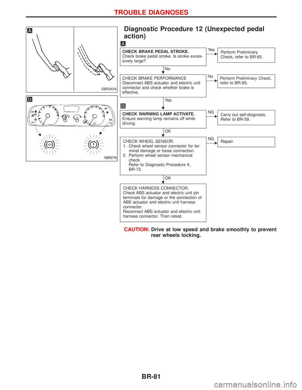
Diagnostic Procedure 12 (Unexpected pedal
action)
CHECK BRAKE PEDAL STROKE.
Check brake pedal stroke. Is stroke exces-
sively large?
No
EYe s
Perform Preliminary
Check, refer to BR-65.
CHECK BRAKE PERFORMANCE
Disconnect ABS actuator and electric unit
connector and check whether brake is
effective.
Ye s
ENo
Perform Preliminary Check,
refer to BR-65.
CHECK WARNING LAMP ACTIVATE.
Ensure warning lamp remains off while
driving.
OK
ENG
Carry out self-diagnosis.
Refer to BR-59.
CHECK WHEEL SENSOR.
1. Check wheel sensor connector for ter-
minal damage or loose connection.
2. Perform wheel sensor mechanical
check.
Refer to Diagnostic Procedure 4,
BR-73.
OK
ENG
Repair.
CHECK HARNESS CONNECTOR.
Check ABS actuator and electric unit pin
terminals for damage or the connection of
ABS actuator and electric unit harness
connector.
Reconnect ABS actuator and electric unit
harness connector. Then retest.
CAUTION:Drive at low speed and brake smoothly to prevent
rear wheels locking.
SBR540A
YBR279
H
H
H
H
TROUBLE DIAGNOSES
BR-81
Page 284 of 1767
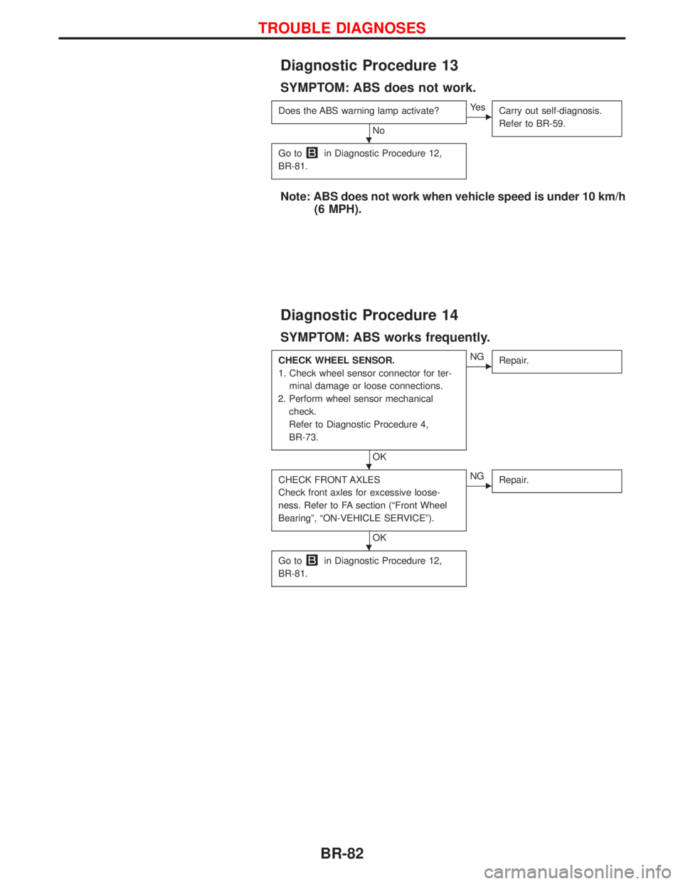
Diagnostic Procedure 13
SYMPTOM: ABS does not work.
Does the ABS warning lamp activate?
No
EYe s
Carry out self-diagnosis.
Refer to BR-59.
Go toin Diagnostic Procedure 12,
BR-81.
Note: ABS does not work when vehicle speed is under 10 km/h
(6 MPH).
Diagnostic Procedure 14
SYMPTOM: ABS works frequently.
CHECK WHEEL SENSOR.
1. Check wheel sensor connector for ter-
minal damage or loose connections.
2. Perform wheel sensor mechanical
check.
Refer to Diagnostic Procedure 4,
BR-73.
OK
ENG
Repair.
CHECK FRONT AXLES
Check front axles for excessive loose-
ness. Refer to FA section (ªFront Wheel
Bearingº, ªON-VEHICLE SERVICEº).
OK
ENG
Repair.
Go toin Diagnostic Procedure 12,
BR-81.
H
H
H
TROUBLE DIAGNOSES
BR-82
Page 285 of 1767
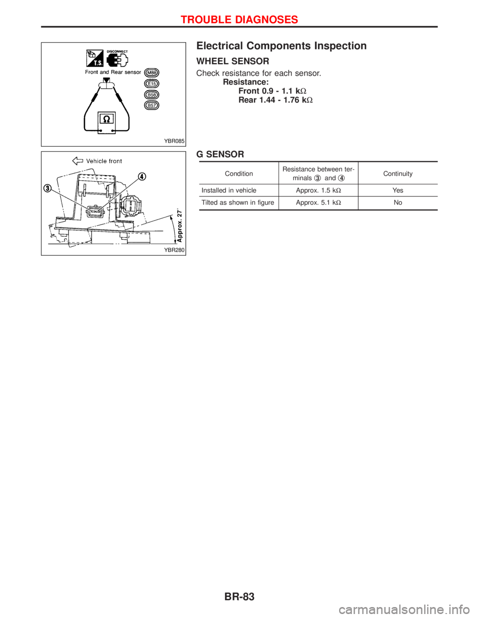
Electrical Components Inspection
WHEEL SENSOR
Check resistance for each sensor.
Resistance:
Front 0.9 - 1.1 kW
Rear 1.44 - 1.76 kW
G SENSOR
ConditionResistance between ter-
minalsq3andq4Continuity
Installed in vehicle Approx. 1.5 kWYe s
Tilted as shown in figure Approx. 5.1 kWNo
YBR085
YBR280
TROUBLE DIAGNOSES
BR-83
Page 290 of 1767
Service Notice
IWhen removing or installing various parts, place a cloth or padding onto the vehicle body to prevent
scratches.
IHandle trim, molding, instruments, grille, etc. carefully during removing or installing. Be careful not to oil
or damage them.
IApply sealing compound where necessary when installing parts.
IWhen applying sealing compound, be careful that the sealing compound does not protrude from parts.
IWhen replacing any metal parts (for example body outer panel, members, etc.), be sure to take rust pre-
vention measures.
Supplemental Restraint System (SRS) ªAIR
BAGº and ªSEAT BELT PRE-TENSIONERº
The Supplemental Restraint System such as ªAIR BAGº and ªSEAT BELT PRE-TENSIONERº used along with
a seat belt, helps to reduce the risk or severity of injury to the driver and front passenger for certain types of
collision. The SRS system composition which is available to NISSAN MODEL R20 is as follows (The compo-
sition varies according to the destination and optional equipment.):
IFor a frontal collision
The Supplemental Restraint System consists of driver air bag module (located in the center of the steer-
ing wheel), front passenger air bag module (located on the instrument panel on passenger side), front seat
belt pre-tensioners, a diagnosis sensor unit, warning lamp, wiring harness and spiral cable.
IFor a side collision
The Supplemental Restraint System consists of front side air bag module (located in the outer side of front
seat), side air bag (satellite) sensor, diagnosis sensor unit (one of components of air bags for a frontal
collision), wiring harness, warning lamp (one of components of air bags for a frontal collision).
Information necessary to service the system safely is included in theRSsection of this Service Manual.
WARNING:
ITo avoid rendering the SRS inoperative, which could increase the risk of personal injury or death
in the event of a collision which would result in air bag inflation, all maintenance should be per-
formed by an authorized NISSAN dealer.
IImproper maintenance, including incorrect removal and installation of the SRS, can lead to per-
sonal injury caused by unintentional activation of the system. For removal of Spiral Cable and Air
Bag Module, see the RS section.
IDo not use electrical test equipment on any circuit related to the SRS unless instructed to in this
Service Manual. Spiral cable and wiring harnesses covered with yellow insulation tape either just
before the harness connectors or for the complete harness are related to the SRS.
PRECAUTIONS
BT-2
Page 363 of 1767
ENGINE CONTROL SYSTEM
SECTION
EC
CONTENTS
ZD30DDTi
TROUBLE DIAGNOSIS - INDEX....................................7
Alphabetical & Numerical Index for DTC ....................7
PRECAUTIONS...............................................................9
Precautions ..................................................................9
ENGINE AND EMISSION CONTROL OVERALL
SYSTEM.........................................................................12
Engine Control Component Parts Location ...............12
Circuit Diagram ..........................................................16
System Diagram ........................................................17
Vacuum Hose Drawing ..............................................18
System Chart .............................................................19
ENGINE AND EMISSION BASIC CONTROL
SYSTEM DESCRIPTION...............................................20
Fuel Injection Control System ...................................20
Fuel Injection Timing Control System........................22
Air Conditioning Cut Control ......................................22
Fuel Cut Control (at no load & high engine
speed) ........................................................................22
Crankcase Ventilation System ...................................23
BASIC SERVICE PROCEDURE...................................24
Injection Tube and Injection Nozzle ..........................24
Electronic Control Fuel Injection Pump .....................27
Air Bleeding ...............................................................32
ON BOARD DIAGNOSTIC SYSTEM
DESCRIPTION...............................................................33
DTC and MI Detection Logic .....................................33
Diagnostic Trouble Code (DTC) ................................33
Malfunction Indicator (MI) ..........................................34
CONSULT-II ...............................................................39
TROUBLE DIAGNOSIS - INTRODUCTION..................46
Introduction ................................................................46
Work Flow ..................................................................48
TROUBLE DIAGNOSIS - BASIC INSPECTION...........50
Basic Inspection.........................................................50
TROUBLE DIAGNOSIS - GENERAL
DESCRIPTION...............................................................56
Symptom Matrix Chart ...............................................56CONSULT-II Reference Value in Data Monitor
Mode ..........................................................................66
Major Sensor Reference Graph in Data Monitor
Mode ..........................................................................68
ECM Terminals and Reference Value .......................69
TROUBLE DIAGNOSIS FOR INTERMITTENT
INCIDENT.......................................................................78
Description .................................................................78
Diagnostic Procedure ................................................78
TROUBLE DIAGNOSIS FOR POWER SUPPLY..........79
Main Power Supply and Ground Circuit ....................79
DTC 0102 MASS AIR FLOW SEN................................88
Component Description .............................................88
CONSULT-II Reference Value in Data Monitor
Mode ..........................................................................88
ECM Terminals and Reference Value .......................88
On Board Diagnosis Logic.........................................88
DTC Confirmation Procedure ....................................89
Wiring Diagram ..........................................................90
Diagnostic Procedure ................................................92
DTC 0103 COOLANT TEMP SEN................................95
Description .................................................................95
On Board Diagnosis Logic.........................................95
DTC Confirmation Procedure ....................................95
Wiring Diagram ..........................................................96
Diagnostic Procedure ................................................97
DTC 0104 VEHICLE SPEED SEN................................99
Description .................................................................99
ECM Terminals and Reference Value .......................99
On Board Diagnosis Logic.........................................99
Overall Function Check ...........................................100
Wiring Diagram ........................................................101
Diagnostic Procedure ..............................................103
DTC 0203 ACCEL POS SW (F/C)..............................104
Description ...............................................................104
CONSULT-II Reference Value in Data Monitor
Mode ........................................................................104
ECM Terminals and Reference Value .....................104
On Board Diagnosis Logic.......................................104
Page 364 of 1767
DTC Confirmation Procedure ..................................105
Wiring Diagram ........................................................106
Diagnostic Procedure ..............................................107
DTC 0208 OVER HEAT...............................................109
Description ...............................................................109
CONSULT-II Reference Value in Data Monitor
Mode ........................................................................109
ECM Terminals and Reference Value ..................... 110
On Board Diagnosis Logic....................................... 110
Overall Function Check ........................................... 111
Wiring Diagram ........................................................ 112
Diagnostic Procedure .............................................. 114
Main 12 Causes of Overheating..............................120
DTC 0301 ECM 2, DTC 0901 ECM 12.......................121
Description ...............................................................121
On Board Diagnosis Logic.......................................121
DTC Confirmation Procedure ..................................121
Diagnostic Procedure ..............................................122
DTC 0402 P9×FUEL TEMP SEN.................................123
Description ...............................................................123
CONSULT-II Reference Value in Data Monitor
Mode ........................................................................124
ECM Terminals and Reference Value .....................124
On Board Diagnosis Logic.......................................124
DTC Confirmation Procedure ..................................125
Wiring Diagram ........................................................126
Diagnostic Procedure ..............................................128
DTC 0403 ACCEL POS SENSOR..............................130
Description ...............................................................130
CONSULT-II Reference Value in Data Monitor
Mode ........................................................................130
ECM Terminals and Reference Value .....................131
On Board Diagnosis Logic.......................................131
DTC Confirmation Procedure ..................................132
Wiring Diagram ........................................................133
Diagnostic Procedure ..............................................135
DTC 0406 INT AIR VOL..............................................143
On Board Diagnosis Logic.......................................143
DTC Confirmation Procedure ..................................143
Diagnostic Procedure ..............................................144
DTC 0407 CRANK POS SEN (TDC)..........................145
Description ...............................................................145
CONSULT-II Reference Value in Data Monitor
Mode ........................................................................145
ECM Terminals and Reference Value .....................145
On Board Diagnosis Logic.......................................146
DTC Confirmation Procedure ..................................146
Wiring Diagram ........................................................147
Diagnostic Procedure ..............................................149
DTC 0502 BATTERY VOLTAGE.................................153
On Board Diagnosis Logic.......................................153
DTC Confirmation Procedure ..................................153Diagnostic Procedure ..............................................153
DTC 0504 A/T COMM LINE........................................155
System Description ..................................................155
ECM Terminals and Reference Value .....................155
On Board Diagnosis Logic.......................................155
DTC Confirmation Procedure ..................................156
Overall Function Check ...........................................156
Wiring Diagram ........................................................157
Diagnostic Procedure ..............................................159
DTC 0701 P1×CAM POS SEN.....................................161
Description ...............................................................161
CONSULT-II Reference Value in Data Monitor
Mode ........................................................................162
ECM Terminals and Reference Value .....................162
On Board Diagnosis Logic.......................................162
DTC Confirmation Procedure ..................................163
Wiring Diagram ........................................................164
Diagnostic Procedure ..............................................166
DTC 0702 P2×TDC PULSE SIG..................................168
Description ...............................................................168
CONSULT-II Reference Value in Data Monitor
Mode ........................................................................169
ECM Terminals and Reference Value .....................169
On Board Diagnosis Logic.......................................169
DTC Confirmation Procedure ..................................170
Wiring Diagram ........................................................171
Diagnostic Procedure ..............................................173
DTC 0703 P3×PUMP COMM LINE..............................175
Description ...............................................................175
CONSULT-II Reference Value in Data Monitor
Mode ........................................................................176
ECM Terminals and Reference Value .....................176
On Board Diagnosis Logic.......................................176
DTC Confirmation Procedure ..................................177
Wiring Diagram ........................................................178
Diagnostic Procedure ..............................................180
DTC 0704 P4×SPILL/V CIRC, DTC 0706 P6×SPILL
VA LV E..........................................................................182
Description ...............................................................182
CONSULT-II Reference Value in Data Monitor
Mode ........................................................................183
ECM Terminals and Reference Value .....................183
On Board Diagnosis Logic.......................................183
DTC Confirmation Procedure ..................................184
Wiring Diagram ........................................................185
Diagnostic Procedure ..............................................187
DTC 0705 P5×PUMP C/MODULE................................189
Description ...............................................................189
CONSULT-II Reference Value in Data Monitor
Mode ........................................................................190
ECM Terminals and Reference Value .....................190
On Board Diagnosis Logic.......................................190
CONTENTS(Cont'd)
EC-2
Page 366 of 1767
CONSULT-II Reference Value in Data Monitor
Mode ........................................................................281
ECM Terminals and Reference Value .....................282
Wiring Diagram ........................................................283
Diagnostic Procedure ..............................................284
AIR CONDITIONER CONTROL..................................289
Wiring Diagram ........................................................289
MI (MIL) & DATA LINK CONNECTORS.....................291
Wiring Diagram ........................................................291
SERVICE DATA AND SPECIFICATIONS (SDS)........292
General Specifications .............................................292
Injection Pump Numbers .........................................292
Injection Nozzle .......................................................292
Engine Coolant Temperature Sensor ......................292
Crankshaft Position Sensor (TDC) ..........................292
Glow Plug ................................................................292
Accelerator Position Sensor ....................................292
EGR Volume Control Valve .....................................292
TD27Ti
TROUBLE DIAGNOSIS - INDEX................................293
Alphabetical & Numerical Index for DTC ................293
PRECAUTIONS AND PREPARATION........................295
Special Service Tools ..............................................295
Engine Fuel & Emission Control System ................297
Precautions ..............................................................298
ENGINE AND EMISSION CONTROL OVERALL
SYSTEM.......................................................................300
Engine Control Component Parts Location .............300
Circuit Diagram ........................................................302
System Diagram ......................................................303
Vacuum Hose Drawing ............................................304
System Chart ...........................................................305
ENGINE AND EMISSION BASIC CONTROL
SYSTEM DESCRIPTION.............................................306
Fuel Injection System ..............................................306
Fuel Injection Timing System ..................................309
Air Conditioning Cut Control .................................... 311
Fuel Cut Control (at high engine speed) ................. 311
Glow Control ............................................................ 311
CRANKCASE VENTILATION SYSTEM......................312
Description ...............................................................312
Blow-by Control Valve .............................................312
Ventilation Hose .......................................................312
INJECTION NOZZLE...................................................313
Removal and Installation .........................................313
Disassembly (No.2-4nozzle) ...............................313
Inspection (No.2-4nozzle) ...................................314
Cleaning (No.2-4nozzle) .....................................314
Assembly (No.2-4nozzle) ....................................315
Test and Adjustment ................................................316
ELECTRONIC FUEL INJECTION PUMP....................318Removal ...................................................................318
Installation ................................................................319
Disassembly and Assembly .....................................320
ON BOARD DIAGNOSTIC SYSTEM
DESCRIPTION.............................................................321
DTC and MI Detection Logic ...................................321
Diagnostic Trouble Code (DTC) ..............................321
Malfunction Indicator (MI) ........................................322
CONSULT-II .............................................................327
TROUBLE DIAGNOSES.............................................334
Introduction ..............................................................334
Diagnostic Worksheet ..............................................335
Work Flow ................................................................336
Description for Work Flow .......................................337
Basic Inspection.......................................................338
Symptom Matrix Chart .............................................340
CONSULT-II Reference Value in Data Monitor
Mode ........................................................................343
Major Sensor Reference Graph in Data Monitor
Mode ........................................................................345
ECM Terminals and Reference Value .....................346
TROUBLE DIAGNOSIS FOR POWER SUPPLY........352
Wiring Diagram ........................................................352
Diagnostic Procedure ..............................................353
DTC P0100 MASS AIR FLOW SEN...........................356
Component Description ...........................................356
On Board Diagnosis Logic.......................................356
DTC Confirmation Procedure ..................................356
Wiring Diagram ........................................................357
Diagnostic Procedure ..............................................359
Component Inspection .............................................360
DTC P0115 COOLANT TEMP SEN............................361
Component Description ...........................................361
On Board Diagnosis Logic.......................................361
DTC Confirmation Procedure ..................................361
Wiring Diagram ........................................................362
Diagnostic Procedure ..............................................363
Component Inspection .............................................364
DTC P0120 ACCEL POS SENSOR............................365
Component Description ...........................................365
On Board Diagnosis Logic.......................................365
DTC Confirmation Procedure A (For General
Plausibility) ...............................................................365
DTC Confirmation Procedure B (For Accelerator
Sticking) ...................................................................366
Wiring Diagram ........................................................367
Diagnostic Procedure ..............................................368
Component Inspection .............................................371
DTC P0180 FUEL TEMP SENSOR............................372
Component Description ...........................................372
On Board Diagnosis Logic.......................................372
DTC Confirmation Procedure ..................................372
CONTENTS(Cont'd)
EC-4