2002 NISSAN TERRANO g sensor
[x] Cancel search: g sensorPage 369 of 1767
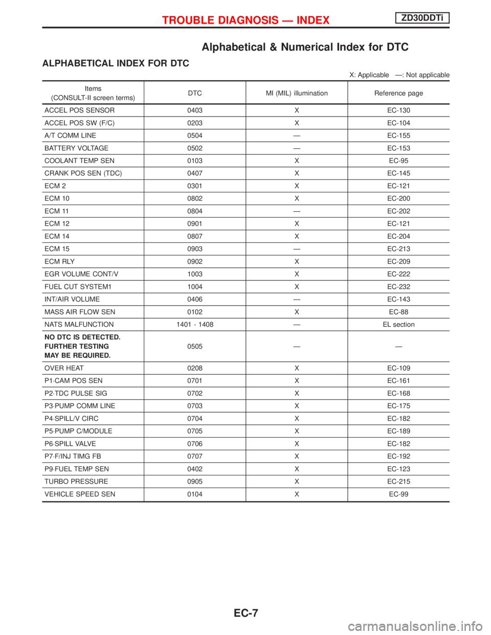
Alphabetical & Numerical Index for DTC
ALPHABETICAL INDEX FOR DTC
X: Applicable Ð: Not applicable
Items
(CONSULT-II screen terms)DTC MI (MIL) illumination Reference page
ACCEL POS SENSOR 0403 X EC-130
ACCEL POS SW (F/C) 0203 X EC-104
A/T COMM LINE 0504 Ð EC-155
BATTERY VOLTAGE 0502 Ð EC-153
COOLANT TEMP SEN 0103 X EC-95
CRANK POS SEN (TDC) 0407 X EC-145
ECM 2 0301 X EC-121
ECM 10 0802 X EC-200
ECM 11 0804 Ð EC-202
ECM 12 0901 X EC-121
ECM 14 0807 X EC-204
ECM 15 0903 Ð EC-213
ECM RLY 0902 X EC-209
EGR VOLUME CONT/V 1003 X EC-222
FUEL CUT SYSTEM1 1004 X EC-232
INT/AIR VOLUME 0406 Ð EC-143
MASS AIR FLOW SEN 0102 X EC-88
NATS MALFUNCTION 1401 - 1408 Ð EL section
NO DTC IS DETECTED.
FURTHER TESTING
MAY BE REQUIRED.0505 Ð Ð
OVER HEAT 0208 X EC-109
P1×CAM POS SEN 0701 X EC-161
P2×TDC PULSE SIG 0702 X EC-168
P3×PUMP COMM LINE 0703 X EC-175
P4×SPILL/V CIRC 0704 X EC-182
P5×PUMP C/MODULE 0705 X EC-189
P6×SPILL VALVE 0706 X EC-182
P7×F/INJ TIMG FB 0707 X EC-192
P9×FUEL TEMP SEN 0402 X EC-123
TURBO PRESSURE 0905 X EC-215
VEHICLE SPEED SEN 0104 X EC-99
TROUBLE DIAGNOSIS Ð INDEXZD30DDTi
EC-7
Page 370 of 1767
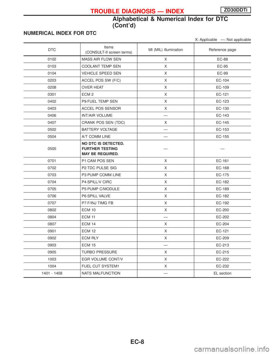
NUMERICAL INDEX FOR DTC
X: Applicable Ð: Not applicable
DTCItems
(CONSULT-II screen terms)MI (MIL) illumination Reference page
0102 MASS AIR FLOW SEN X EC-88
0103 COOLANT TEMP SEN X EC-95
0104 VEHICLE SPEED SEN X EC-99
0203 ACCEL POS SW (F/C) X EC-104
0208 OVER HEAT X EC-109
0301 ECM 2 X EC-121
0402 P9×FUEL TEMP SEN X EC-123
0403 ACCEL POS SENSOR X EC-130
0406 INT/AIR VOLUME Ð EC-143
0407 CRANK POS SEN (TDC) X EC-145
0502 BATTERY VOLTAGE Ð EC-153
0504 A/T COMM LINE Ð EC-155
0505NO DTC IS DETECTED.
FURTHER TESTING
MAY BE REQUIRED.ÐÐ
0701 P1×CAM POS SEN X EC-161
0702 P2×TDC PULSE SIG X EC-168
0703 P3×PUMP COMM LINE X EC-175
0704 P4×SPILL/V CIRC X EC-182
0705 P5×PUMP C/MODULE X EC-189
0706 P6×SPILL VALVE X EC-182
0707 P7×F/INJ TIMG FB X EC-192
0802 ECM 10 X EC-200
0804 ECM 11 Ð EC-202
0807 ECM 14 X EC-204
0901 ECM 12 X EC-121
0902 ECM RLY X EC-209
0903 ECM 15 Ð EC-213
0905 TURBO PRESSURE X EC-215
1003 EGR VOLUME CONT/V X EC-222
1004 FUEL CUT SYSTEM1 X EC-232
1401 - 1408 NATS MALFUNCTION Ð EL section
TROUBLE DIAGNOSIS Ð INDEXZD30DDTi
Alphabetical & Numerical Index for DTC
(Cont'd)
EC-8
Page 373 of 1767
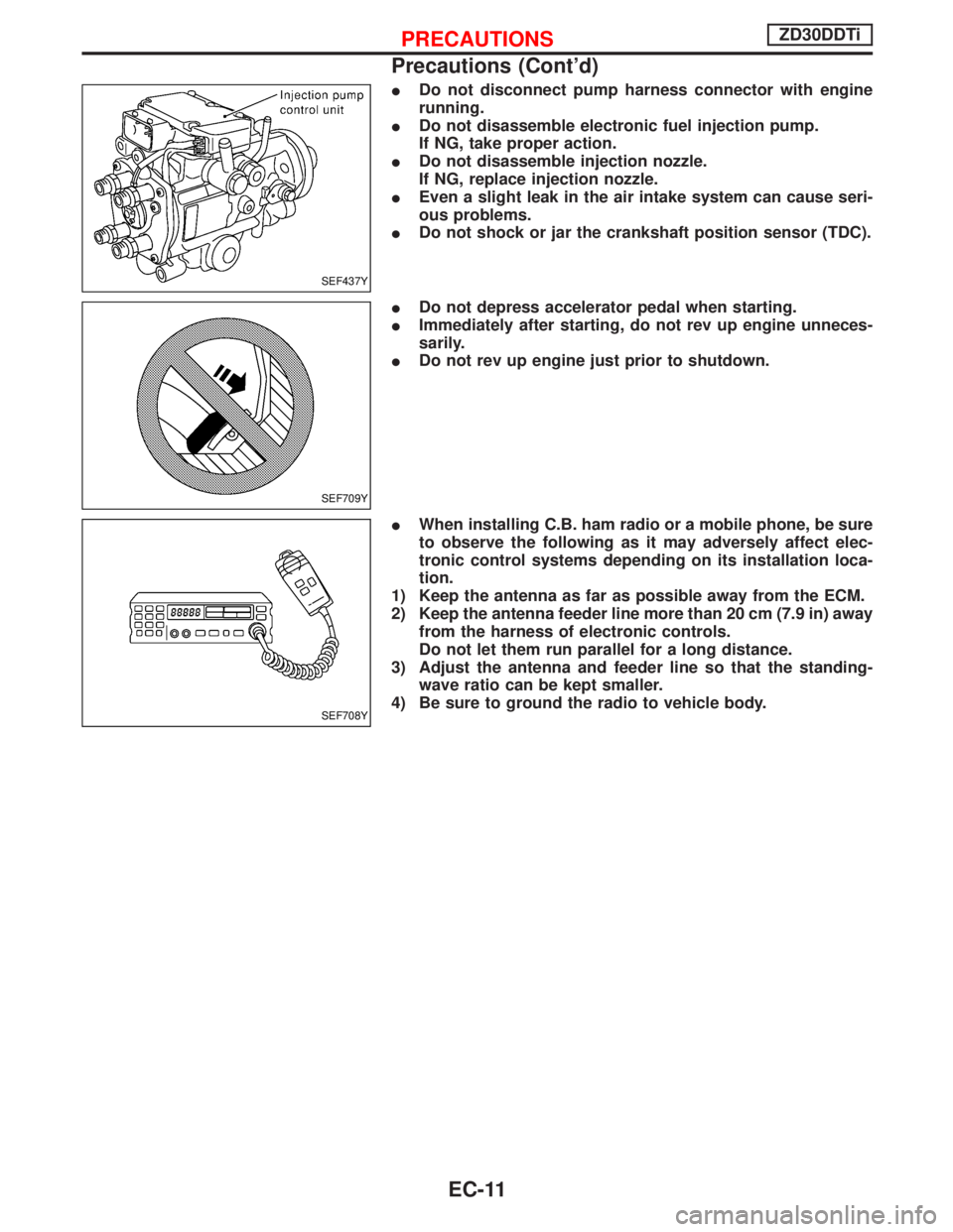
IDo not disconnect pump harness connector with engine
running.
IDo not disassemble electronic fuel injection pump.
If NG, take proper action.
IDo not disassemble injection nozzle.
If NG, replace injection nozzle.
IEven a slight leak in the air intake system can cause seri-
ous problems.
IDo not shock or jar the crankshaft position sensor (TDC).
IDo not depress accelerator pedal when starting.
IImmediately after starting, do not rev up engine unneces-
sarily.
IDo not rev up engine just prior to shutdown.
IWhen installing C.B. ham radio or a mobile phone, be sure
to observe the following as it may adversely affect elec-
tronic control systems depending on its installation loca-
tion.
1) Keep the antenna as far as possible away from the ECM.
2) Keep the antenna feeder line more than 20 cm (7.9 in) away
from the harness of electronic controls.
Do not let them run parallel for a long distance.
3) Adjust the antenna and feeder line so that the standing-
wave ratio can be kept smaller.
4) Be sure to ground the radio to vehicle body.
SEF437Y
SEF709Y
SEF708Y
PRECAUTIONSZD30DDTi
Precautions (Cont'd)
EC-11
Page 381 of 1767
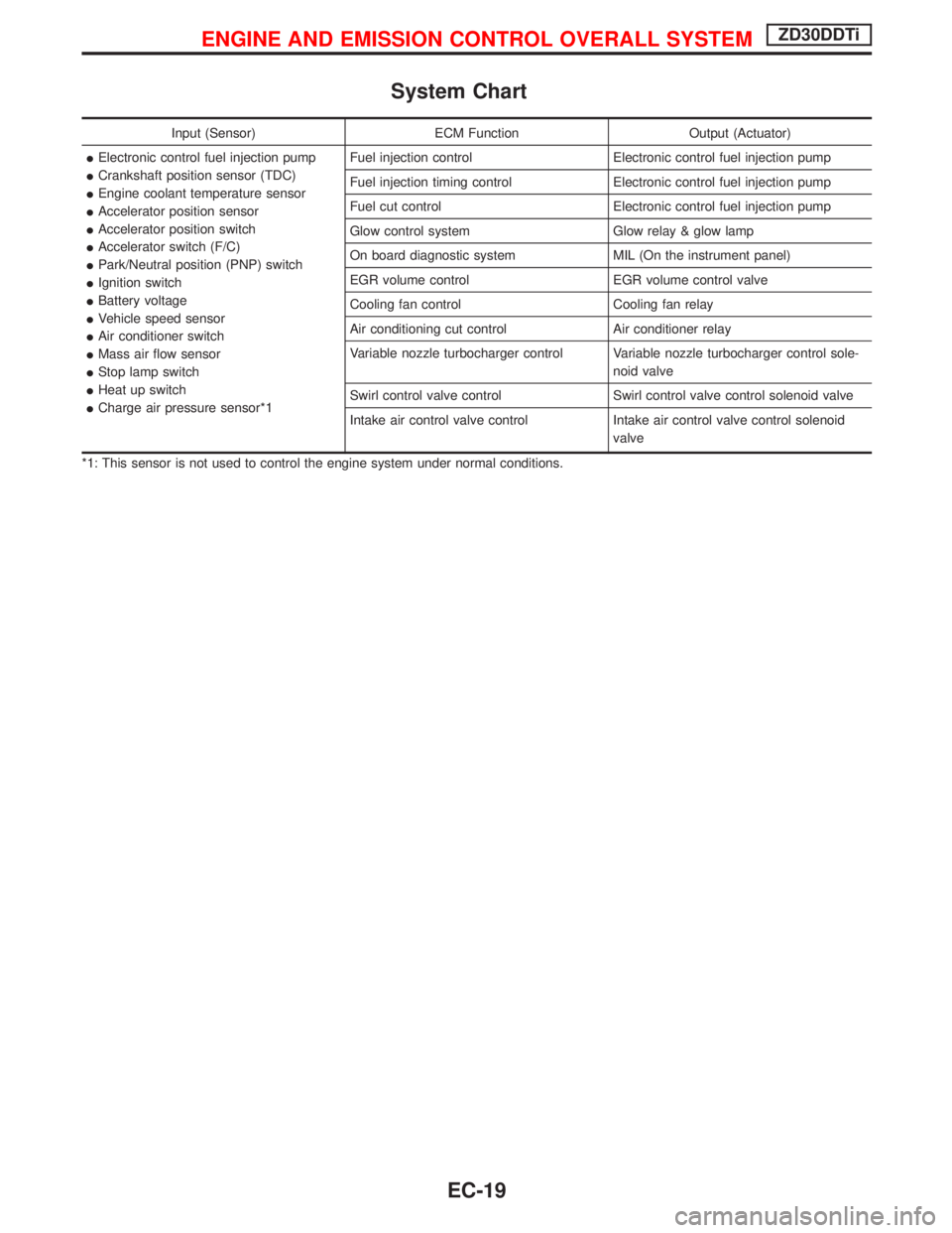
System Chart
Input (Sensor) ECM Function Output (Actuator)
IElectronic control fuel injection pump
ICrankshaft position sensor (TDC)
IEngine coolant temperature sensor
IAccelerator position sensor
IAccelerator position switch
IAccelerator switch (F/C)
IPark/Neutral position (PNP) switch
IIgnition switch
IBattery voltage
IVehicle speed sensor
IAir conditioner switch
IMass air flow sensor
IStop lamp switch
IHeat up switch
ICharge air pressure sensor*1Fuel injection control Electronic control fuel injection pump
Fuel injection timing control Electronic control fuel injection pump
Fuel cut control Electronic control fuel injection pump
Glow control system Glow relay & glow lamp
On board diagnostic system MIL (On the instrument panel)
EGR volume control EGR volume control valve
Cooling fan control Cooling fan relay
Air conditioning cut control Air conditioner relay
Variable nozzle turbocharger control Variable nozzle turbocharger control sole-
noid valve
Swirl control valve control Swirl control valve control solenoid valve
Intake air control valve control Intake air control valve control solenoid
valve
*1: This sensor is not used to control the engine system under normal conditions.
ENGINE AND EMISSION CONTROL OVERALL SYSTEMZD30DDTi
EC-19
Page 382 of 1767
Fuel Injection Control System
DESCRIPTION
System description
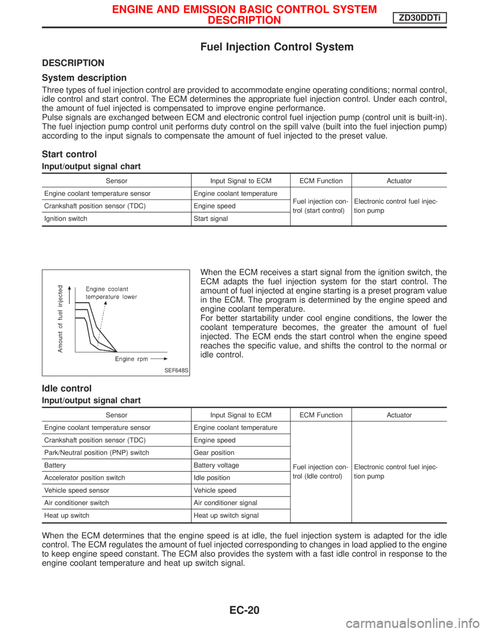
Three types of fuel injection control are provided to accommodate engine operating conditions; normal control,
idle control and start control. The ECM determines the appropriate fuel injection control. Under each control,
the amount of fuel injected is compensated to improve engine performance.
Pulse signals are exchanged between ECM and electronic control fuel injection pump (control unit is built-in).
The fuel injection pump control unit performs duty control on the spill valve (built into the fuel injection pump)
according to the input signals to compensate the amount of fuel injected to the preset value.
Start control
Input/output signal chart
Sensor Input Signal to ECM ECM Function Actuator
Engine coolant temperature sensor Engine coolant temperature
Fuel injection con-
trol (start control)Electronic control fuel injec-
tion pump Crankshaft position sensor (TDC) Engine speed
Ignition switch Start signal
When the ECM receives a start signal from the ignition switch, the
ECM adapts the fuel injection system for the start control. The
amount of fuel injected at engine starting is a preset program value
in the ECM. The program is determined by the engine speed and
engine coolant temperature.
For better startability under cool engine conditions, the lower the
coolant temperature becomes, the greater the amount of fuel
injected. The ECM ends the start control when the engine speed
reaches the specific value, and shifts the control to the normal or
idle control.
Idle control
Input/output signal chart
Sensor Input Signal to ECM ECM Function Actuator
Engine coolant temperature sensor Engine coolant temperature
Fuel injection con-
trol (Idle control)Electronic control fuel injec-
tion pump Crankshaft position sensor (TDC) Engine speed
Park/Neutral position (PNP) switch Gear position
Battery Battery voltage
Accelerator position switch Idle position
Vehicle speed sensor Vehicle speed
Air conditioner switch Air conditioner signal
Heat up switch Heat up switch signal
When the ECM determines that the engine speed is at idle, the fuel injection system is adapted for the idle
control. The ECM regulates the amount of fuel injected corresponding to changes in load applied to the engine
to keep engine speed constant. The ECM also provides the system with a fast idle control in response to the
engine coolant temperature and heat up switch signal.
SEF648S
ENGINE AND EMISSION BASIC CONTROL SYSTEM
DESCRIPTIONZD30DDTi
EC-20
Page 383 of 1767
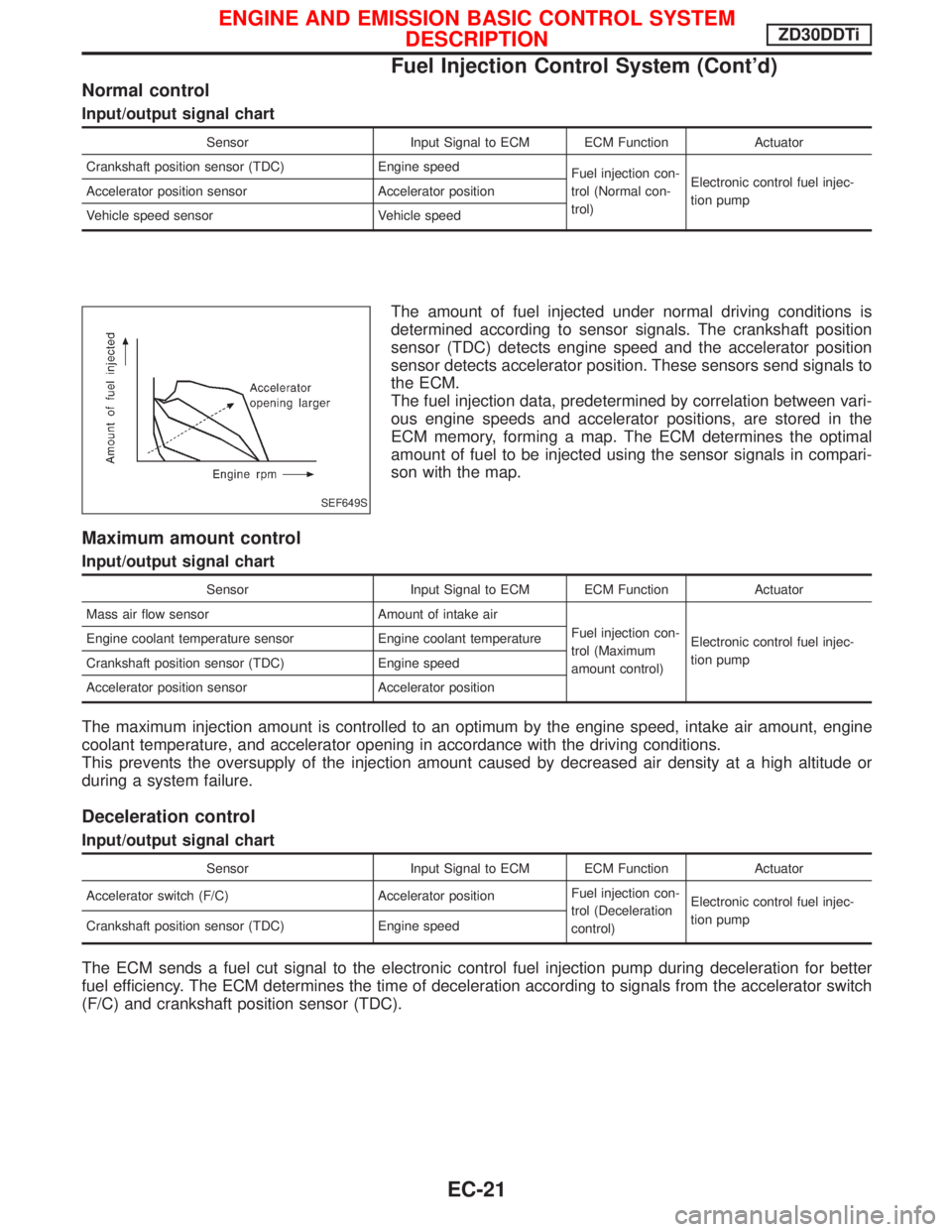
Normal control
Input/output signal chart
Sensor Input Signal to ECM ECM Function Actuator
Crankshaft position sensor (TDC) Engine speed
Fuel injection con-
trol (Normal con-
trol)Electronic control fuel injec-
tion pump Accelerator position sensor Accelerator position
Vehicle speed sensor Vehicle speed
The amount of fuel injected under normal driving conditions is
determined according to sensor signals. The crankshaft position
sensor (TDC) detects engine speed and the accelerator position
sensor detects accelerator position. These sensors send signals to
the ECM.
The fuel injection data, predetermined by correlation between vari-
ous engine speeds and accelerator positions, are stored in the
ECM memory, forming a map. The ECM determines the optimal
amount of fuel to be injected using the sensor signals in compari-
son with the map.
Maximum amount control
Input/output signal chart
Sensor Input Signal to ECM ECM Function Actuator
Mass air flow sensor Amount of intake air
Fuel injection con-
trol (Maximum
amount control)Electronic control fuel injec-
tion pump Engine coolant temperature sensor Engine coolant temperature
Crankshaft position sensor (TDC) Engine speed
Accelerator position sensor Accelerator position
The maximum injection amount is controlled to an optimum by the engine speed, intake air amount, engine
coolant temperature, and accelerator opening in accordance with the driving conditions.
This prevents the oversupply of the injection amount caused by decreased air density at a high altitude or
during a system failure.
Deceleration control
Input/output signal chart
Sensor Input Signal to ECM ECM Function Actuator
Accelerator switch (F/C) Accelerator positionFuel injection con-
trol (Deceleration
control)Electronic control fuel injec-
tion pump
Crankshaft position sensor (TDC) Engine speed
The ECM sends a fuel cut signal to the electronic control fuel injection pump during deceleration for better
fuel efficiency. The ECM determines the time of deceleration according to signals from the accelerator switch
(F/C) and crankshaft position sensor (TDC).
SEF649S
ENGINE AND EMISSION BASIC CONTROL SYSTEM
DESCRIPTIONZD30DDTi
Fuel Injection Control System (Cont'd)
EC-21
Page 384 of 1767
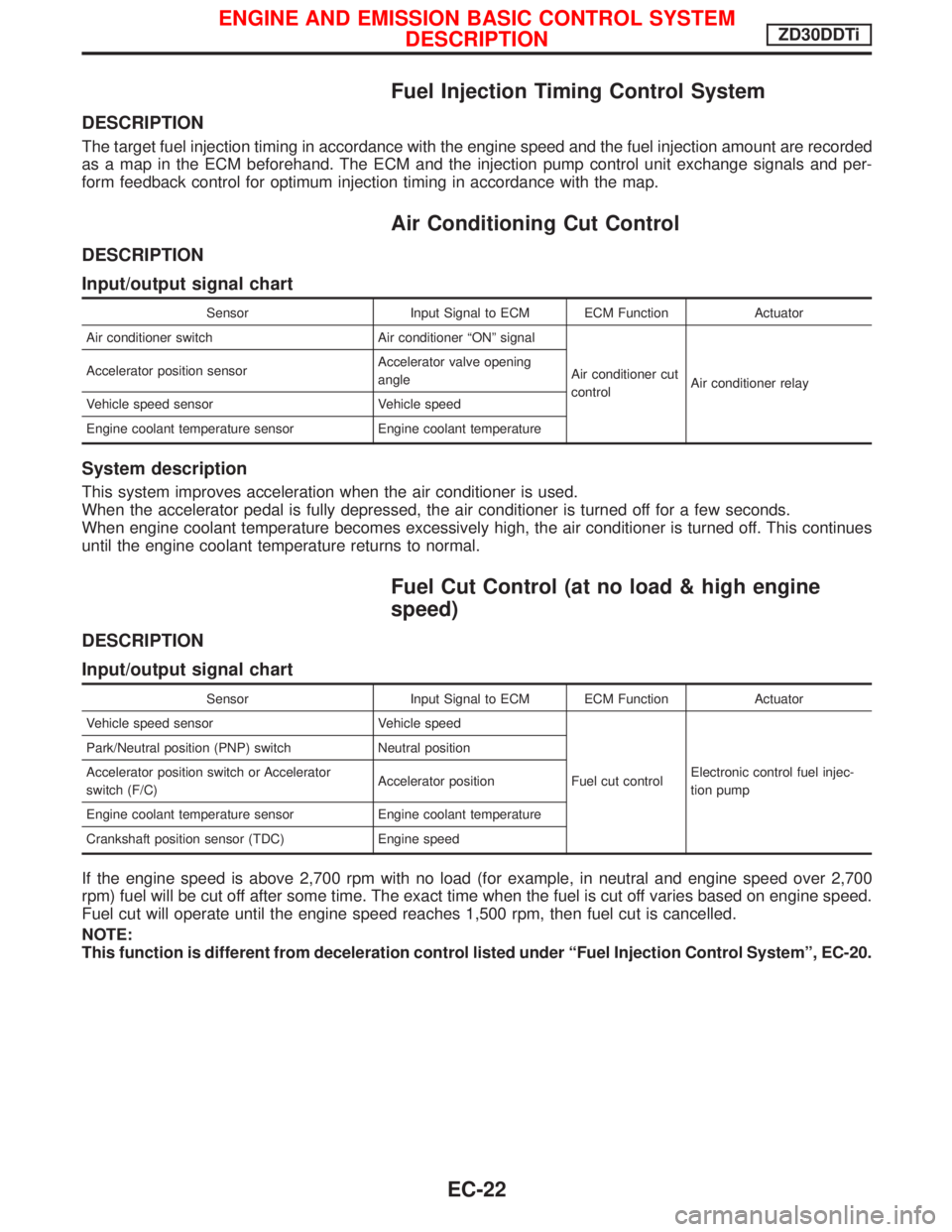
Fuel Injection Timing Control System
DESCRIPTION
The target fuel injection timing in accordance with the engine speed and the fuel injection amount are recorded
as a map in the ECM beforehand. The ECM and the injection pump control unit exchange signals and per-
form feedback control for optimum injection timing in accordance with the map.
Air Conditioning Cut Control
DESCRIPTION
Input/output signal chart
Sensor Input Signal to ECM ECM Function Actuator
Air conditioner switch Air conditioner ªONº signal
Air conditioner cut
controlAir conditioner relay Accelerator position sensorAccelerator valve opening
angle
Vehicle speed sensor Vehicle speed
Engine coolant temperature sensor Engine coolant temperature
System description
This system improves acceleration when the air conditioner is used.
When the accelerator pedal is fully depressed, the air conditioner is turned off for a few seconds.
When engine coolant temperature becomes excessively high, the air conditioner is turned off. This continues
until the engine coolant temperature returns to normal.
Fuel Cut Control (at no load & high engine
speed)
DESCRIPTION
Input/output signal chart
Sensor Input Signal to ECM ECM Function Actuator
Vehicle speed sensor Vehicle speed
Fuel cut controlElectronic control fuel injec-
tion pump Park/Neutral position (PNP) switch Neutral position
Accelerator position switch or Accelerator
switch (F/C)Accelerator position
Engine coolant temperature sensor Engine coolant temperature
Crankshaft position sensor (TDC) Engine speed
If the engine speed is above 2,700 rpm with no load (for example, in neutral and engine speed over 2,700
rpm) fuel will be cut off after some time. The exact time when the fuel is cut off varies based on engine speed.
Fuel cut will operate until the engine speed reaches 1,500 rpm, then fuel cut is cancelled.
NOTE:
This function is different from deceleration control listed under ªFuel Injection Control Systemº, EC-20.
ENGINE AND EMISSION BASIC CONTROL SYSTEM
DESCRIPTIONZD30DDTi
EC-22
Page 402 of 1767
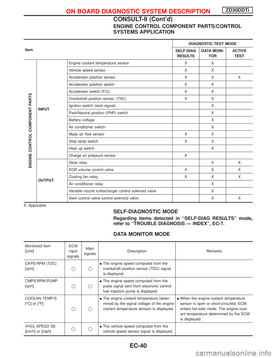
ENGINE CONTROL COMPONENT PARTS/CONTROL
SYSTEMS APPLICATION
ItemDIAGNOSTIC TEST MODE
SELF-DIAG
RESULTSDATA MONI-
TORACTIVE
TEST
ENGINE CONTROL COMPONENT PARTS
INPUTEngine coolant temperature sensor X X
Vehicle speed sensor X X
Accelerator position sensor X X X
Accelerator position switch X X
Accelerator switch (F/C) X X
Crankshaft position sensor (TDC) X X
Ignition switch (start signal) X
Park/Neutral position (PNP) switch X
Battery voltage X
Air conditioner switch X
Mass air flow sensor X X
Stop lamp switch X X
Heat up switch X
Charge air pressure sensor X
OUTPUTGlow relayXX
EGR volume control valve X X X
Cooling fan relay X X X
Air conditioner relay X
Variable nozzle turbocharger control solenoid valve X
Swirl control valve control solenoid valve X X
X: Applicable
SELF-DIAGNOSTIC MODE
Regarding items detected in ªSELF-DIAG RESULTSº mode,
refer to ªTROUBLE DIAGNOSIS Ð INDEXº, EC-7.
DATA MONITOR MODE
Monitored item
[Unit]ECM
input
signalsMain
signalsDescription Remarks
CKPS×RPM (TDC)
[rpm]qqIThe engine speed computed from the
crankshaft position sensor (TDC) signal
is displayed.
CMPS×RPM×PUMP
[rpm]qqIThe engine speed computed from the
pulse signal sent from electronic control
fuel injection pump is displayed.
COOLAN TEMP/S
[ÉC] or [ÉF]
qqIThe engine coolant temperature (deter-
mined by the signal voltage of the engine
coolant temperature sensor) is displayed.IWhen the engine coolant temperature
sensor is open or short-circuited, ECM
enters fail-safe mode. The engine cool-
ant temperature determined by the ECM
is displayed.
VHCL SPEED SE
[km/h] or [mph]qqIThe vehicle speed computed from the
vehicle speed sensor signal is displayed.
ON BOARD DIAGNOSTIC SYSTEM DESCRIPTIONZD30DDTi
CONSULT-II (Cont'd)
EC-40