Page 204 of 1767

Diagnostic Procedure 2 (Warning lamp stays on
when ignition switch is turned ON)............................69
Diagnostic Procedure 3 (ABS actuator solenoid
valve and solenoid valve relay) .................................71
Diagnostic Procedure 4 (Wheel sensor or rotor) ......73
Diagnostic Procedure 5 (Motor Relay or motor) .......75
Diagnostic Procedure 7 (Low voltage) ......................77
Diagnostic Procedure 8 (G sensor) ...........................78
Diagnostic Procedure 9 (Control unit) .......................79
Diagnostic Procedure 10 (Pedal vibration and
noise) .........................................................................80Diagnostic Procedure 11 (Long stopping
distance) ....................................................................80
Diagnostic Procedure 12 (Unexpected pedal
action) ........................................................................81
Diagnostic Procedure 13 ...........................................82
Diagnostic Procedure 14 ...........................................82
Electrical Components Inspection .............................83
SERVICE DATA AND SPECIFICATIONS (SDS)..........84
General Specifications ...............................................84
Inspection and Adjustment ........................................85
CONTENTS(Cont'd)
BR-2
Page 205 of 1767

Supplement Restraint System (SRS) ªAIR BAGº
and ªSEAT BELT PRE-TENSIONERº
The Supplemental Restraint System ªAir Bagº and ªSeat Belt Pre-tensionerº, used along with a seat belt, help
to reduce the risk or severity or injury to the driver and front passenger in a collision. The Supplemental
Restraint System consists of an air bag module (located in the center of the steering wheel and on the instru-
ment panel on the passenger side, where fitted), seat belt pre-tensioners, a diagnosis sensor unit, warning
lamp, wiring harness and spiral cable. Information necessary to service the system safely is included in the
BT sectionof this Service Manual.
WARNING:
ITo avoid rendering the SRS inoperative (which could increase the risk of personal injury or death
in the event of a collision which would result in air bag inflation), all maintenance must be per-
formed by an authorized NISSAN dealer.
IImproper maintenance, including incorrect removal and installation of the SRS, can lead to per-
sonal injury caused by unintentional activation of the system.
IDo not use electrical test equipment on any circuit related to the SRS unless instructed to in this
Service Manual. SRS wiring harnesses (except ªSEAT BELT-TENSIONERº connector) can be iden-
tified with yellow harness connector and with yellow harness protector or yellow insulation tape
before the harness connectors.
Precautions
IUse only ªDOT 4º fluid from a sealed container.
INever reuse drained brake fluid.
IBe careful not to splash brake fluid on painted areas; it
may cause paint damage. If brake fluid is splashed on
painted areas, wash it away with water immediately.
ITo clean master cylinder parts, disc brake caliper parts or
wheel cylinder parts, use clean brake fluid.
INever use mineral oils such as Petrol or kerosene. They
will ruin rubber parts of hydraulic system.
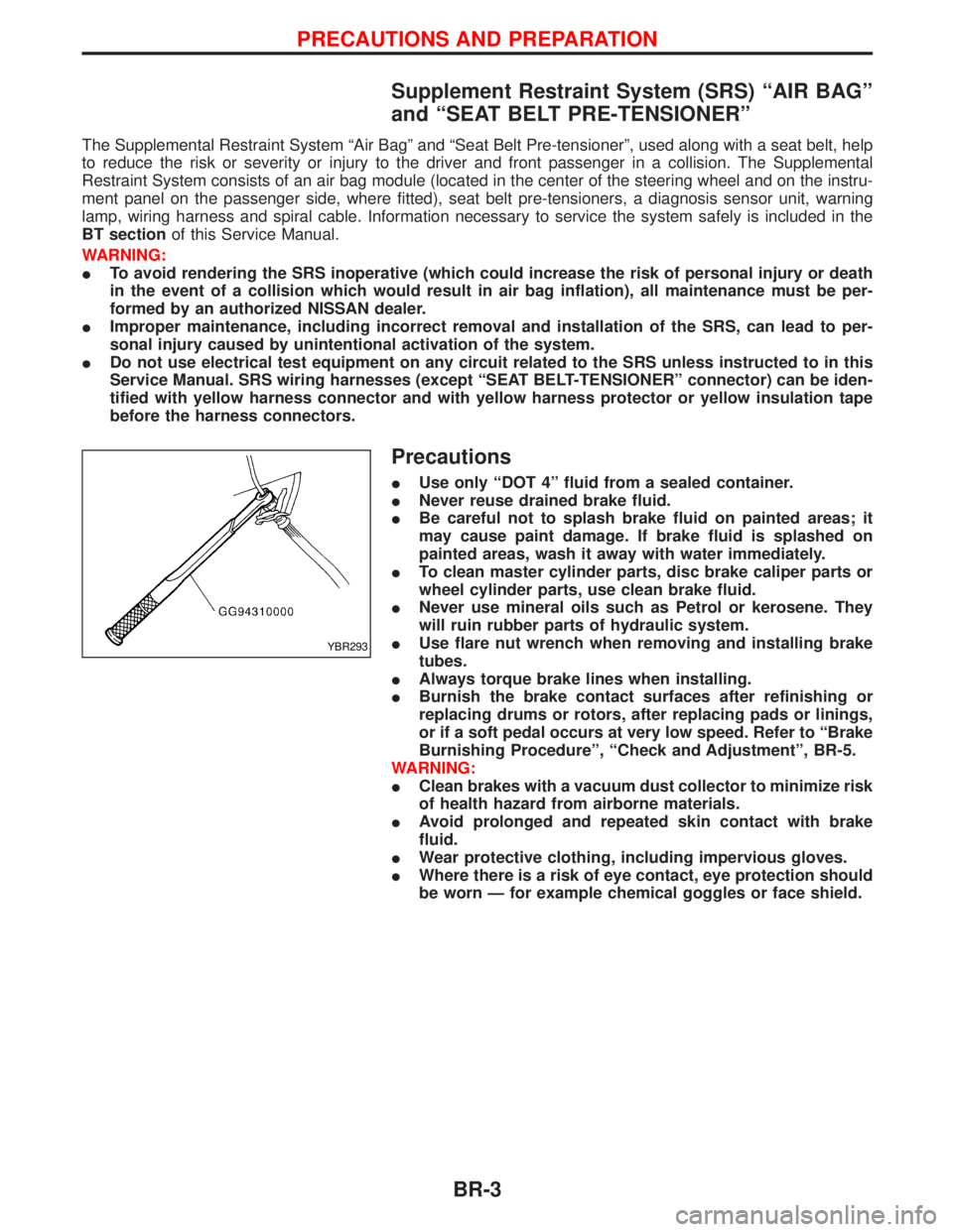
IUse flare nut wrench when removing and installing brake
tubes.
IAlways torque brake lines when installing.
IBurnish the brake contact surfaces after refinishing or
replacing drums or rotors, after replacing pads or linings,
or if a soft pedal occurs at very low speed. Refer to ªBrake
Burnishing Procedureº, ªCheck and Adjustmentº, BR-5.
WARNING:
IClean brakes with a vacuum dust collector to minimize risk
of health hazard from airborne materials.
IAvoid prolonged and repeated skin contact with brake
fluid.
IWear protective clothing, including impervious gloves.
IWhere there is a risk of eye contact, eye protection should
be worn Ð for example chemical goggles or face shield.
YBR293
PRECAUTIONS AND PREPARATION
BR-3
Page 206 of 1767
Preparation
SPECIAL SERVICE TOOLS
Tool number
Tool nameDescription
GG94310000
Flare nut torque wrench
Removing and installing each brake pip-
ing
KV991V0010
Brake fluid pressure
gauge
Measuring brake fluid pressure
HT72480000
Rear axle shaft bearing
puller
Removing rear wheel sensor rotor
PRECAUTIONS AND PREPARATION
BR-4
Page 215 of 1767

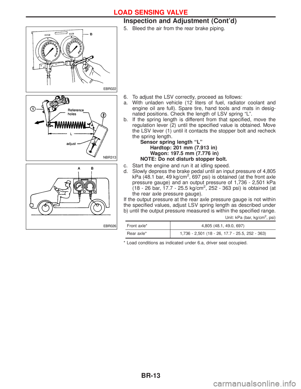
5. Bleed the air from the rear brake piping.
6. To adjust the LSV correctly, proceed as follows:
a. With unladen vehicle (12 liters of fuel, radiator coolant and
engine oil are full). Spare tire, hand tools and mats in desig-
nated positions. Check the length of LSV spring ªLº.
b. If the spring length is different from that specified, move the
regulation lever (2) until the specified value is obtained. Move
the LSV lever (1) until it contacts the stopper bolt and recheck
the spring length.
Sensor spring length ªLº
Hardtop: 201 mm (7.913 in)
Wagon: 197.5 mm (7.776 in)
NOTE: Do not disturb stopper bolt.
c. Start the engine and run it at idling speed.
d. Slowly depress the brake pedal until an input pressure of 4,805
kPa (48.1 bar, 49 kg/cm
2, 697 psi) is obtained (at the front axle
pressure gauge) and an output pressure of 1,736 - 2,501 kPa
(18 - 26 bar, 17.7 - 25.5 kg/cm
2, 252 - 363 psi) is obtained (at
the rear axle pressure gauge).
If the output pressure at the rear axle pressure gauge is not within
the specified values, adjust LSV spring length as described under
b) until the output pressure measured is within the specified range.
Unit: kPa (bar, kg/cm2, psi)
Front axle* 4,805 (48.1, 49.0, 697)
Rear axle* 1,736 - 2,501 (18 - 26, 17.7 - 25.5, 252 - 363)
* Load conditions as indicated under 6.a, driver seat occupied.
EBR022
NBR313
EBR026
LOAD SENSING VALVE
Inspection and Adjustment (Cont'd)
BR-13
Page 240 of 1767

System Description
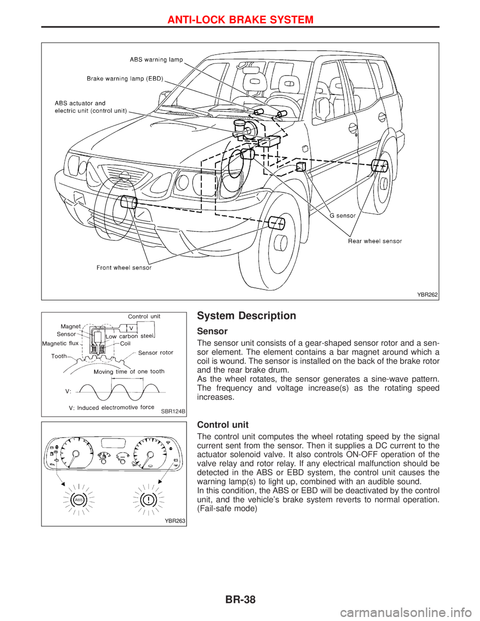
Sensor
The sensor unit consists of a gear-shaped sensor rotor and a sen-
sor element. The element contains a bar magnet around which a
coil is wound. The sensor is installed on the back of the brake rotor
and the rear brake drum.
As the wheel rotates, the sensor generates a sine-wave pattern.
The frequency and voltage increase(s) as the rotating speed
increases.
Control unit
The control unit computes the wheel rotating speed by the signal
current sent from the sensor. Then it supplies a DC current to the
actuator solenoid valve. It also controls ON-OFF operation of the
valve relay and rotor relay. If any electrical malfunction should be
detected in the ABS or EBD system, the control unit causes the
warning lamp(s) to light up, combined with an audible sound.
In this condition, the ABS or EBD will be deactivated by the control
unit, and the vehicle's brake system reverts to normal operation.
(Fail-safe mode)
YBR262
SBR124B
YBR263
ANTI-LOCK BRAKE SYSTEM
BR-38
Page 241 of 1767
G SENSOR
The G sensor analyses deceleration during braking to determine whether the vehicle is being driven on a road
with low surface resistance () (snow-covered road, etc.). The ABS control unit uses the signal from the
deceleration sensor to compensate for road surface conditions when controlling the braking operation.
NBR136
ANTI-LOCK BRAKE SYSTEM
System Description (Cont'd)
BR-39
Page 244 of 1767
Removal and Installation
CAUTION:
Be careful not to damage sensor edge and sensor rotor teeth.
When removing the front or rear wheel hub assembly, discon-
nect the ABS wheel sensor from the assembly and move it
away.
FRONT WHEEL SENSOR
REAR WHEEL SENSOR
NBR122
SBR399D
ANTI-LOCK BRAKE SYSTEM
BR-42
Page 245 of 1767
FRONT SENSOR ROTOR
Removal
1. Remove the drive shaft and rear wheel hub. Refer to ªFront axle
Ð drive shaftº in FA section and ªRear axleº in RA section.
2. Remove the sensor rotor using suitable puller, drift and bear-
ing replacer.
Installation
Install the sensor rotor. For front sensor rotor, use hammer and
wooden block. For rear sensor rotor, use suitable drift and press.
IAlways replace sensor rotor with new one.
YBR295
YBR296
ANTI-LOCK BRAKE SYSTEM
Removal and Installation (Cont'd)
BR-43