Page 98 of 1767
4. SPORT Indicator Lamp Does Not Come On
SYMPTOM:
SPORT indicator lamp does not come on for about 3 seconds
when depressing and releasing accelerator pedal fully.
Does self-diagnosis show damage to
throttle (accelerator) position sensor cir-
cuit?
Ye s
ENo
Check throttle (accelerator)
position sensor. Refer to
AT-60.
Check throttle (accelerator) position sen-
sor. Ð Refer to EC section [TROUBLE
DIAGNOSIS FOR ªTHROTTLE (ACCEL)
POSI SENº (DTC 43)].
OK
ENG
Repair or replace throttle
(accelerator) position sen-
sor.
1. Perform TCM input/output signal
inspection.
2. If NG, recheck TCM pin terminals for
damage or loose connection with har-
ness connector.
NAT309
YAT337
NAT262
H
H
DIAGNOSTIC PROCEDURES FOR SYMPTOMS
AT-96
Page 101 of 1767
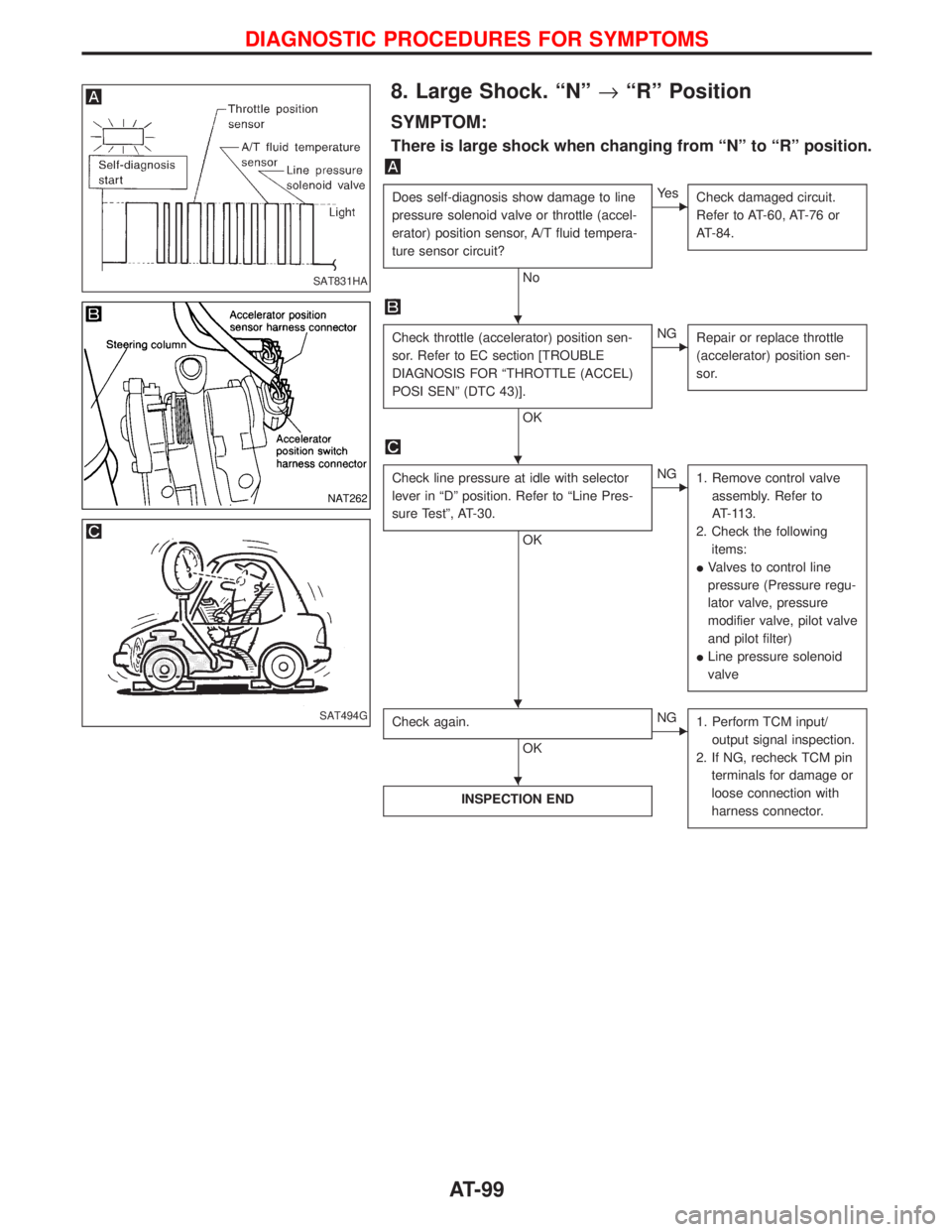
8. Large Shock. ªNº®ªRº Position
SYMPTOM:
There is large shock when changing from ªNº to ªRº position.
Does self-diagnosis show damage to line
pressure solenoid valve or throttle (accel-
erator) position sensor, A/T fluid tempera-
ture sensor circuit?
No
EYe s
Check damaged circuit.
Refer to AT-60, AT-76 or
AT-84.
Check throttle (accelerator) position sen-
sor. Refer to EC section [TROUBLE
DIAGNOSIS FOR ªTHROTTLE (ACCEL)
POSI SENº (DTC 43)].
OK
ENG
Repair or replace throttle
(accelerator) position sen-
sor.
Check line pressure at idle with selector
lever in ªDº position. Refer to ªLine Pres-
sure Testº, AT-30.
OK
ENG
1. Remove control valve
assembly. Refer to
AT-113.
2. Check the following
items:
IValves to control line
pressure (Pressure regu-
lator valve, pressure
modifier valve, pilot valve
and pilot filter)
ILine pressure solenoid
valve
Check again.
OK
ENG
1. Perform TCM input/
output signal inspection.
2. If NG, recheck TCM pin
terminals for damage or
loose connection with
harness connector.
INSPECTION END
SAT831HA
NAT262
SAT494G
H
H
H H
H
DIAGNOSTIC PROCEDURES FOR SYMPTOMS
AT-99
Page 104 of 1767
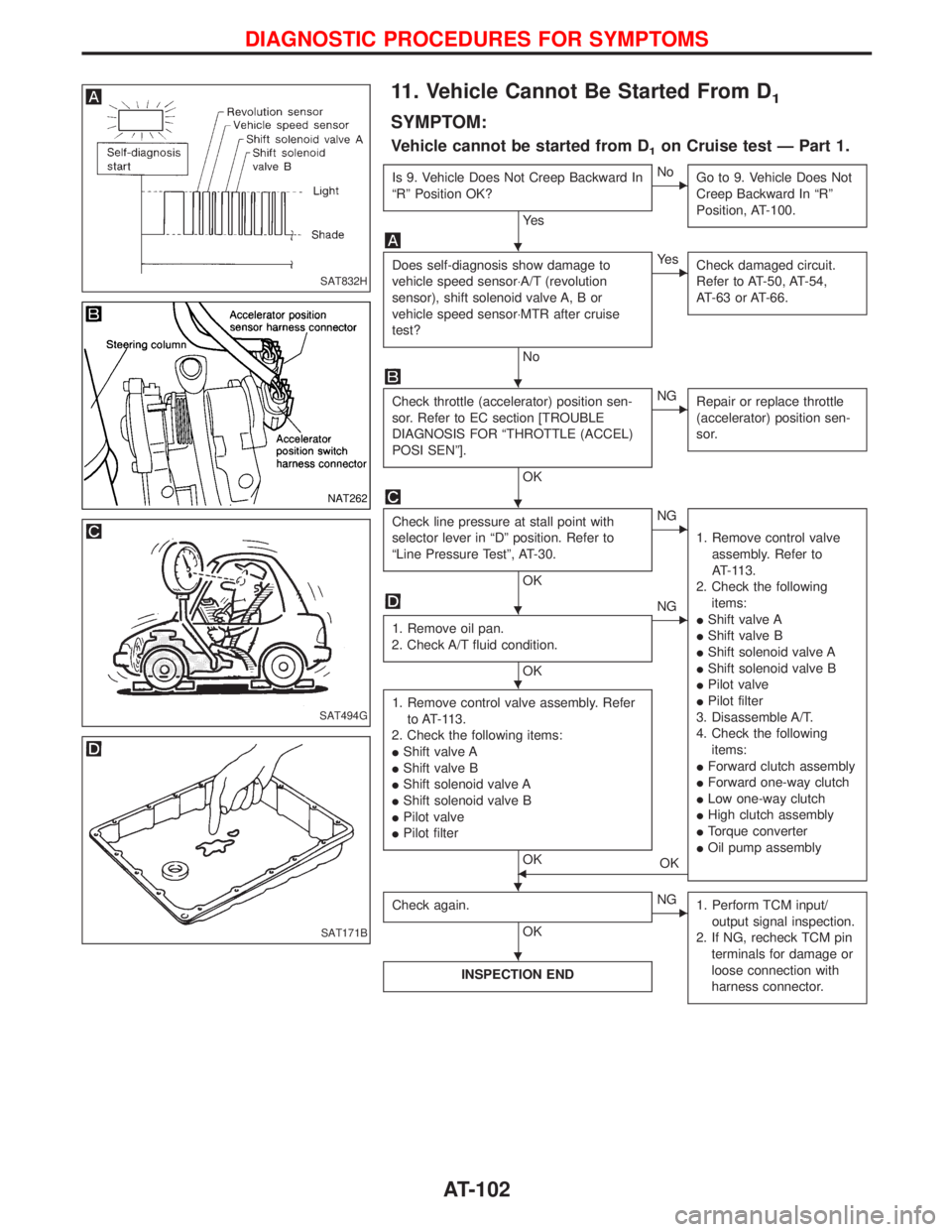
11. Vehicle Cannot Be Started From D1
SYMPTOM:
Vehicle cannot be started from D1on Cruise test Ð Part 1.
Is 9. Vehicle Does Not Creep Backward In
ªRº Position OK?
Ye s
ENo
Go to 9. Vehicle Does Not
Creep Backward In ªRº
Position, AT-100.
Does self-diagnosis show damage to
vehicle speed sensor×A/T (revolution
sensor), shift solenoid valve A, B or
vehicle speed sensor×MTR after cruise
test?
No
EYe s
Check damaged circuit.
Refer to AT-50, AT-54,
AT-63 or AT-66.
Check throttle (accelerator) position sen-
sor. Refer to EC section [TROUBLE
DIAGNOSIS FOR ªTHROTTLE (ACCEL)
POSI SENº].
OK
ENG
Repair or replace throttle
(accelerator) position sen-
sor.
Check line pressure at stall point with
selector lever in ªDº position. Refer to
ªLine Pressure Testº, AT-30.
OK
ENG
1. Remove control valve
assembly. Refer to
AT-113.
2. Check the following
items:
IShift valve A
IShift valve B
IShift solenoid valve A
IShift solenoid valve B
IPilot valve
IPilot filter
3. Disassemble A/T.
4. Check the following
items:
IForward clutch assembly
IForward one-way clutch
ILow one-way clutch
IHigh clutch assembly
ITorque converter
IOil pump assembly
1. Remove oil pan.
2. Check A/T fluid condition.
OK
ENG
1. Remove control valve assembly. Refer
to AT-113.
2. Check the following items:
IShift valve A
IShift valve B
IShift solenoid valve A
IShift solenoid valve B
IPilot valve
IPilot filter
OKFOK
Check again.
OK
ENG
1. Perform TCM input/
output signal inspection.
2. If NG, recheck TCM pin
terminals for damage or
loose connection with
harness connector.
INSPECTION END
SAT832H
NAT262
SAT494G
SAT171B
H
H
H
H
H
H H
H
DIAGNOSTIC PROCEDURES FOR SYMPTOMS
AT-102
Page 105 of 1767
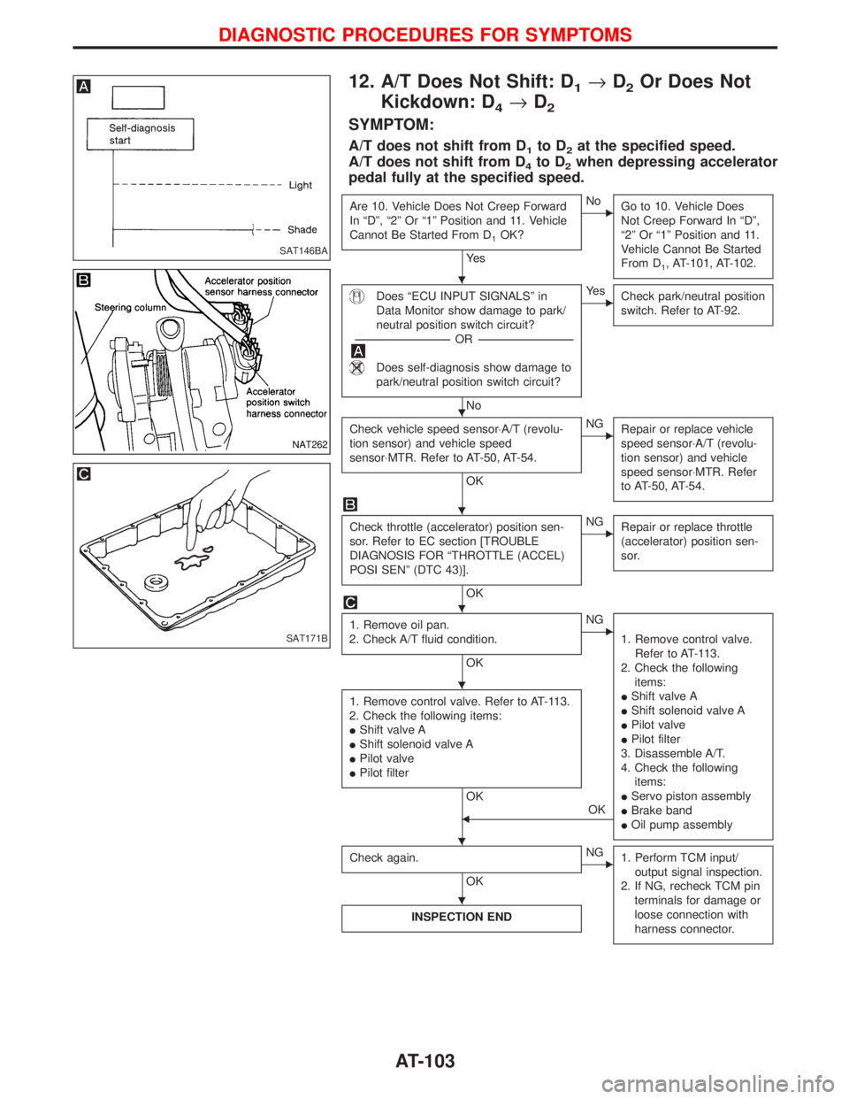
12. A/T Does Not Shift: D1®D2Or Does Not
Kickdown: D
4®D2
SYMPTOM:
A/T does not shift from D1to D2at the specified speed.
A/T does not shift from D
4to D2when depressing accelerator
pedal fully at the specified speed.
Are 10. Vehicle Does Not Creep Forward
In ªDº, ª2º Or ª1º Position and 11. Vehicle
Cannot Be Started From D
1OK?
Ye s
ENo
Go to 10. Vehicle Does
Not Creep Forward In ªDº,
ª2º Or ª1º Position and 11.
Vehicle Cannot Be Started
From D
1, AT-101, AT-102.
Does ªECU INPUT SIGNALSº in
Data Monitor show damage to park/
neutral position switch circuit?
-----------------------------------------------------------------------------------------------------------------------OR -----------------------------------------------------------------------------------------------------------------------
Does self-diagnosis show damage to
park/neutral position switch circuit?
No
EYe s
Check park/neutral position
switch. Refer to AT-92.
Check vehicle speed sensor×A/T (revolu-
tion sensor) and vehicle speed
sensor×MTR. Refer to AT-50, AT-54.
OK
ENG
Repair or replace vehicle
speed sensor×A/T (revolu-
tion sensor) and vehicle
speed sensor×MTR. Refer
to AT-50, AT-54.
Check throttle (accelerator) position sen-
sor. Refer to EC section [TROUBLE
DIAGNOSIS FOR ªTHROTTLE (ACCEL)
POSI SENº (DTC 43)].
OK
ENG
Repair or replace throttle
(accelerator) position sen-
sor.
1. Remove oil pan.
2. Check A/T fluid condition.
OK
ENG
1. Remove control valve.
Refer to AT-113.
2. Check the following
items:
IShift valve A
IShift solenoid valve A
IPilot valve
IPilot filter
3. Disassemble A/T.
4. Check the following
items:
IServo piston assembly
IBrake band
IOil pump assembly
1. Remove control valve. Refer to AT-113.
2. Check the following items:
IShift valve A
IShift solenoid valve A
IPilot valve
IPilot filter
OK
FOK
Check again.
OK
ENG
1. Perform TCM input/
output signal inspection.
2. If NG, recheck TCM pin
terminals for damage or
loose connection with
harness connector.
INSPECTION END
SAT146BA
NAT262
SAT171B
H
H
H
H
H
H H
H
DIAGNOSTIC PROCEDURES FOR SYMPTOMS
AT-103
Page 107 of 1767
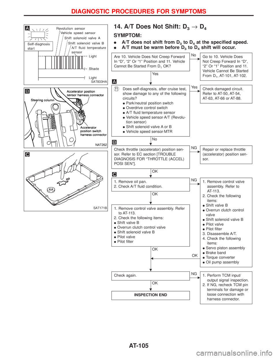
14. A/T Does Not Shift: D3®D4
SYMPTOM:
IA/T does not shift from D3to D4at the specified speed.
IA/T must be warm before D
3to D4shift will occur.
Are 10. Vehicle Does Not Creep Forward
In ªDº, ª2º Or ª1º Position and 11. Vehicle
Cannot Be Started From D
1OK?
Ye s
ENo
Go to 10. Vehicle Does
Not Creep Forward In ªDº,
ª2º Or ª1º Position and 11.
Vehicle Cannot Be Started
From D
1, AT-101, AT-102.
Does self-diagnosis, after cruise test,
show damage to any of the following
circuits?
IPark/neutral position switch
IOverdrive control switch
IA/T fluid temperature sensor
IVehicle speed sensor×A/T (Revolu-
tion sensor)
IShift solenoid valve A or B
IVehicle speed sensor×MTR
No
EYe s
Check damaged circuit.
Refer to AT-50, AT-54,
AT-63, AT-66 or AT-88.
Check throttle (accelerator) position sen-
sor. Refer to EC section [TROUBLE
DIAGNOSIS FOR ªTHROTTLE (ACCEL)
POSI SENº].
OK
ENG
Repair or replace throttle
(accelerator) position sen-
sor.
1. Remove oil pan.
2. Check A/T fluid condition.
OK
ENG
1. Remove control valve
assembly. Refer to
AT-113.
2. Check the following
items:
IShift valve B
IOverrun clutch control
valve
IShift solenoid valve B
IPilot valve
IPilot filter
3. Disassemble A/T.
4. Check the following
items:
IServo piston assembly
IBrake band
ITorque converter
IOil pump assembly
1. Remove control valve assembly. Refer
to AT-113.
2. Check the following items:
IShift valve B
IOverrun clutch control valve
IShift solenoid valve B
IPilot valve
IPilot filter
OK
FOK
Check again.
OK
ENG
1. Perform TCM input/
output signal inspection.
2. If NG, recheck TCM pin
terminals for damage or
loose connection with
harness connector.
INSPECTION END
SAT833HA
NAT262
SAT171B
H
H
H
H
H H
H
DIAGNOSTIC PROCEDURES FOR SYMPTOMS
AT-105
Page 111 of 1767
19. Vehicle Does Not Start From D1
SYMPTOM:
Vehicle does not start from D1on Cruise test Ð Part 2.
Does self-diagnosis show damage to
vehicle speed sensor×A/T (revolution
sensor), shift solenoid valve A, B or
vehicle speed sensor×MTR after cruise
test?
No
EYe s
Check damaged circuit.
Refer to AT-50, AT-54,
AT-63 or AT-66.
Check again.
OK
ENG
1. Perform TCM input/
output signal inspection.
2. If NG, recheck TCM pin
terminals for damage or
loose connection with
harness connector.
Go to 11. Vehicle Cannot Be Started From
D
1, AT-102.
SAT832H
H H
H
DIAGNOSTIC PROCEDURES FOR SYMPTOMS
AT-109
Page 112 of 1767
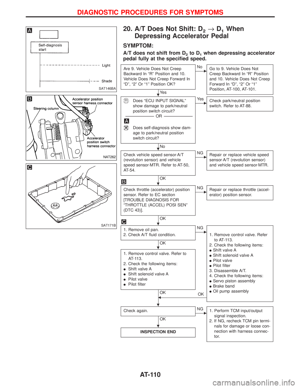
20. A/T Does Not Shift: D2®D1When
Depressing Accelerator Pedal
SYMPTOM:
A/T does not shift from D2to D1when depressing accelerator
pedal fully at the specified speed.
Are 9. Vehicle Does Not Creep
Backward In ªRº Position and 10.
Vehicle Does Not Creep Forward In
ªDº, ª2º Or ª1º Position OK?
Ye s
ENo
Go to 9. Vehicle Does Not
Creep Backward In ªRº Position
and 10. Vehicle Does Not Creep
Forward In ªDº, ª2º Or ª1º
Position, AT-100, AT-101.
Does ªECU INPUT SIGNALº
show damage to park/neutral
position switch circuit?
-----------------------------------------------------------------------------------------------------OR -----------------------------------------------------------------------------------------------------
Does self-diagnosis show dam-
age to park/neutral position
switch circuit?
No
EYe s
Check park/neutral position
switch. Refer to AT-88.
Check vehicle speed sensor×A/T
(revolution sensor) and vehicle
speed sensor×MTR. Refer to AT-50,
AT-54.
OK
ENG
Repair or replace vehicle speed
sensor×A/T (revolution sensor)
and vehicle speed sensor×MTR.
Check throttle (accelerator) position
sensor. Refer to EC section
[TROUBLE DIAGNOSIS FOR
ªTHROTTLE (ACCEL) POSI SENº
(DTC 43)].
OK
ENG
Repair or replace throttle (accel-
erator) position sensor.
1. Remove oil pan.
2. Check A/T fluid condition.
OK
ENG
1. Remove control valve. Refer
to AT-113.
2. Check the following items:
IShift valve A
IShift solenoid valve A
IPilot valve
IPilot filter
3. Disassemble A/T.
4. Check the following items:
IServo piston assembly
IBrake band
IOil pump assembly
1. Remove control valve. Refer to
AT-113.
2. Check the following items:
IShift valve A
IShift solenoid valve A
IPilot valve
IPilot filter
OKFOK
Check again.
OK
ENG
1. Perform TCM input/output
signal inspection.
2. If NG, recheck TCM pin termi-
nals for damage or loose con-
nection with harness connec-
tor.
INSPECTION END
SAT146BA
NAT262
SAT171B
H
H
H
H
H
H
H
DIAGNOSTIC PROCEDURES FOR SYMPTOMS
AT-110
Page 115 of 1767
Control Valve Assembly and Accumulators
REMOVAL
1. Remove exhaust front tube.
2. Remove oil pan and gasket and drain ATF.
3. Remove A/T fluid temperature sensor if necessary.
4. Remove oil strainer.
5. Remove control valve assembly by removing fixing bolts and
disconnecting harness connector.
Bolt length and location
Bolt symbolmm (in)
qA33 (1.30)
q
B45 (1.77)
6. Remove solenoids and valves from valve body if necessary.
7. Remove terminal cord assembly if necessary.
8. Remove accumulatorq
A,qB,qCandqDby applying compressed
air if necessary.
IHold each piston with rag.
9. Reinstall any part removed.
IAlways use new sealing parts.
NAT277
SAT073BA
SAT353B
SAT074BA
ON-VEHICLE SERVICE
AT-113