Page 246 of 1767
REAR SENSOR ROTOR
Removal
IRemove the sensor rotor using Tool.
Installation
Install the sensor rotor using suitable drift and press.
IAlways replace sensor rotor with new one.
IPay attention to the direction of front sensor rotor as shown in
figure.
CONTROL UNIT
Location: Built-in ABS actuator.
When disconnecting the harness connector, pull the lever as
shown in figure.
G SENSOR
Always replace G sensor if bumped or dropped. Otherwise,
performance characteristics of G sensor will be changed,
which in turn alters ABS control performance characteristics.
SBR401D
SBR402D
NBR212
NBR127
ANTI-LOCK BRAKE SYSTEM
Removal and Installation (Cont'd)
BR-44
Page 249 of 1767

How to Perform Trouble Diagnoses for Quick
and Accurate Repair
INTRODUCTION
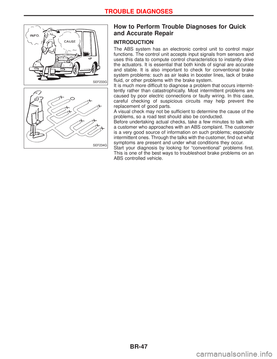
The ABS system has an electronic control unit to control major
functions. The control unit accepts input signals from sensors and
uses this data to compute control characteristics to instantly drive
the actuators. It is essential that both kinds of signal are accurate
and stable. It is also important to check for conventional brake
system problems: such as air leaks in booster lines, lack of brake
fluid, or other problems with the brake system.
It is much more difficult to diagnose a problem that occurs intermit-
tently rather than catastrophically. Most intermittent problems are
caused by poor electric connections or faulty wiring. In this case,
careful checking of suspicious circuits may help prevent the
replacement of good parts.
A visual check may not be sufficient to determine the cause of the
problems, so a road test should also be conducted.
Before undertaking actual checks, take a few minutes to talk with
a customer who approaches with an ABS complaint. The customer
is a very good source of information on such problems; especially
intermittent ones. Through the talks with the customer, find out what
symptoms are present and under what conditions they occur.
Start your diagnosis by looking for ªconventionalº problems first.
This is one of the best ways to troubleshoot brake problems on an
ABS controlled vehicle.
SEF233G
SEF234G
TROUBLE DIAGNOSES
BR-47
Page 260 of 1767
CONSULT-II
CONSULT-II APPLICATION TO ABS
ITEMSELF-DIAGNOSTIC
RESULTSDATA MONITOR ACTIVE TEST
Front right wheel sensor X X Ð
Front left wheel sensor X X Ð
Rear right wheel sensor X X Ð
Rear left wheel sensor X X Ð
G switch (G sensor) X X X
Stop lamp switch Ð X Ð
Front right inlet solenoid valve X X X
Front right outlet solenoid valve X X X
Front left inlet solenoid valve X X X
Front left outlet solenoid valve X X X
Rear inlet solenoid valve X X X
Rear outlet solenoid valve X X X
Actuator solenoid valve relay X X Ð
Actuator motor relay
(ABS MOTOR is shown on the Data Monitor
screen.)XXX
ABS warning lamp Ð X Ð
Brake warning lamp Ð X Ð
Battery voltage X X Ð
ABS Operating Signal Ð Ð Ð
X: Applicable
Ð: Not applicable
ECU (ABS control unit) part number mode
Ignore the ECU part number displayed in the ECU PART NUMBER MODE. Refer to parts catalog to order
the ECU.
TROUBLE DIAGNOSES
BR-58
Page 262 of 1767
![NISSAN TERRANO 2002 Service Repair Manual SELF-DIAGNOSTIC RESULTS MODE
Diagnostic item Diagnostic item is detected when...Diagnostic
procedure
FR RH SENSORH
[OPEN]ICircuit for front right wheel sensor is open.
(An abnormally high input voltag NISSAN TERRANO 2002 Service Repair Manual SELF-DIAGNOSTIC RESULTS MODE
Diagnostic item Diagnostic item is detected when...Diagnostic
procedure
FR RH SENSORH
[OPEN]ICircuit for front right wheel sensor is open.
(An abnormally high input voltag](/manual-img/5/57393/w960_57393-261.png)
SELF-DIAGNOSTIC RESULTS MODE
Diagnostic item Diagnostic item is detected when...Diagnostic
procedure
FR RH SENSORH
[OPEN]ICircuit for front right wheel sensor is open.
(An abnormally high input voltage is entered.)4
FR LH SENSORH
[OPEN]ICircuit for front left wheel sensor is open.
(An abnormally high input voltage is entered.)4
RR RH SENSORH
[OPEN]ICircuit for rear right sensor is open.
(An abnormally high input voltage is entered.)4
RR LH SENSORH
[OPEN]ICircuit for rear left sensor is open.
(An abnormally high input voltage is entered.)4
FR RH SENSORH
[SHORT]ICircuit for front right wheel sensor is shorted.
(An abnormally low input voltage is entered.)4
FR LH SENSORH
[SHORT]ICircuit for front left wheel sensor is shorted.
(An abnormally low input voltage is entered.)4
RR RH SENSORH
[SHORT]ICircuit for rear right sensor is shorted.
(An abnormally low input voltage is entered.)4
RR LH SENSORH
[SHORT]ICircuit for rear left sensor is shorted.
(An abnormally low input voltage is entered.)4
ABS SENSORH
[ABNORMAL SIGNAL]ITeeth damage on sensor rotor or misalignment of wheel sensor.
(Abnormal wheel sensor signal is entered.)4
FR RH IN ABS SOL
[OPEN, SHORT]ICircuit for front right inlet solenoid valve is open or shorted.
(An abnormally low output voltage is entered.)3
FR LH IN ABS SOL
[OPEN, SHORT]ICircuit for front left inlet solenoid valve is open or shorted.
(An abnormally low output voltage is entered.)3
FR RH OUT ABS SOL
[OPEN, SHORT]ICircuit for front right outlet solenoid valve is open or shorted.
(An abnormally low output voltage is entered.)3
FR LH OUT ABS SOL
[OPEN, SHORT]ICircuit for front left outlet solenoid valve is open or shorted.
(An abnormally low output voltage is entered.)3
RR IN ABS SOL
[OPEN, SHORT]ICircuit for rear right outlet solenoid valve is open or shorted.
(An abnormally high output voltage is entered.)3
RR OUT ABS SOL
[OPEN, SHORT]ICircuit for rear left outlet solenoid valve is open or shorted.
(An abnormally high output voltage is entered.)3
ABS ACTUATOR RELAY
[ABNORMAL]IActuator solenoid valve relay is ON, even if control unit sends OFF signal.
IActuator solenoid valve relay is OFF, even if control unit sends ON signal.6
ABS MOTOR RELAY
[ABNORMAL]ICircuit for ABS motor relay is open or shorted.
ICircuit for actuator motor is open or shorted.
IActuator motor relay is stuck.5
BATTERY VOLT
[VB-LOW]IPower source voltage supplied to ABS control unit is abnormally low. 7
CONTROL UNITIFunction of calculation in ABS control unit has failed. 9
G-SENSOR
[ABNORMAL]IG sensor is open.8
HIf a tire slips on rough roads for more than 10 seconds, the ABS warning lamp may come on. In this case, the malfunctioning code
regarding the wheel sensors may be memorized. Turn off the ignition switch, restart the engine and drive the vehicle at speeds
above 30 km/h (19 MPH).
TROUBLE DIAGNOSES
CONSULT-II Inspection Procedure (Cont'd)
BR-60
Page 264 of 1767

DATA MONITOR MODE
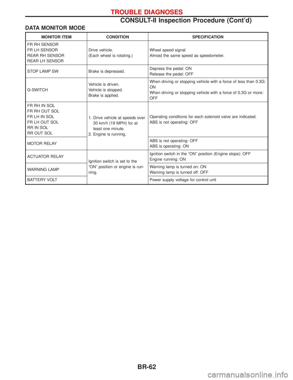
MONITOR ITEM CONDITION SPECIFICATION
FR RH SENSOR
FR LH SENSOR
REAR RH SENSOR
REAR LH SENSORDrive vehicle.
(Each wheel is rotating.)Wheel speed signal
Almost the same speed as speedometer.
STOP LAMP SW Brake is depressed.Depress the pedal: ON
Release the pedal: OFF
G-SWITCHVehicle is driven.
Vehicle is stopped.
Brake is applied.When driving or stopping vehicle with a force of less than 0.3G:
ON
When driving or stopping vehicle with a force of 0.3G or more:
OFF
FR RH IN SOL
FR RH OUT SOL
FR LH IN SOL
FR LH OUT SOL
RR IN SOL
RR OUT SOL1. Drive vehicle at speeds over
30 km/h (19 MPH) for at
least one minute.
2. Engine is running.Operating conditions for each solenoid valve are indicated.
ABS is not operating: OFF
MOTOR RELAYABS is not operating: OFF
ABS is operating: ON
ACTUATOR RELAY
Ignition switch is set to the
ªONº position or engine is run-
ning.Ignition switch in the ªONº position (Engine stops): OFF
Engine running: ON
WARNING LAMPWarning lamp is turned on: ON
Warning lamp is turned off: OFF
BATTERY VOLT Power supply voltage for control unit
TROUBLE DIAGNOSES
CONSULT-II Inspection Procedure (Cont'd)
BR-62
Page 275 of 1767

Diagnostic Procedure 4 (Wheel sensor or rotor)
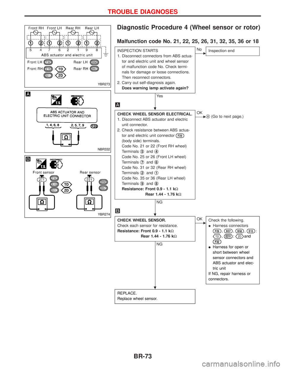
Malfunction code No. 21, 22, 25, 26, 31, 32, 35, 36 or 18
INSPECTION STARTS
1. Disconnect connectors from ABS actua-
tor and electric unit and wheel sensor
of malfunction code No. Check termi-
nals for damage or loose connections.
Then reconnect connectors.
2. Carry out self-diagnosis again.
Does warning lamp activate again?
Ye s
ENo
Inspection end
CHECK WHEEL SENSOR ELECTRICAL.
1. Disconnect ABS actuator and electric
unit connector.
2. Check resistance between ABS actua-
tor and electric unit connector
F29
(body side) terminals.
Code No. 21 or 22 (Front RH wheel)
Terminalsq
5andq4
Code No. 25 or 26 (Front LH wheel)
Terminalsq
7andq6
Code No. 31 or 32 (Rear RH wheel)
Terminalsq
2andq1
Code No. 35 or 36 (Rear LH wheel)
Terminalsq
9andq8
Resistance: Front 0.9 - 1.1 kW
Rear 1.44 - 1.76 kW
NG
EOK
qA(Go to next page.)
CHECK WHEEL SENSOR.
Check each sensor for resistance.
Resistance: Front 0.9 - 1.1 kW
Rear 1.44 - 1.76 kW
NG
EOK
Check the following.
IHarness connectors
F29,B57,B58,E15:
,E211:and
F32
IHarness for open or
short between wheel
sensor connectors and
ABS actuator and elec-
tric unit
If NG, repair harness or
connectors.
REPLACE.
Replace wheel sensor.
YBR273
NBR332
YBR274
H
H
H
TROUBLE DIAGNOSES
BR-73
Page 276 of 1767
qA
Note Note
CHECK TIRE.
Check for inflation pressure, wear and size
of each tire.
OK
ENG
Adjust tire pressure or
replace tire(s).
Note
CHECK WHEEL BEARING
Check wheel bearing axial end play.
OK
Note Note
CHECK SENSOR ROTOR.
Check sensor rotor for teeth damage.
OK
ENG
Replace sensor rotor.
CHECK HARNESS CONNECTOR.
Check ABS actuator and electric unit pin
terminals for damage or the connection of
ABS actuator and electric unit harness
connector.
Reconnect ABS actuator and electric unit
harness connector. Then retest.
Note: Wheel position should be distinguished by code num-
bers except code No. 18 (sensor rotor).
H
H
H
H
TROUBLE DIAGNOSES
Diagnostic Procedure 4 (Wheel sensor or rotor)
(Cont'd)
BR-74
Page 280 of 1767

Diagnostic Procedure 8 (G sensor)
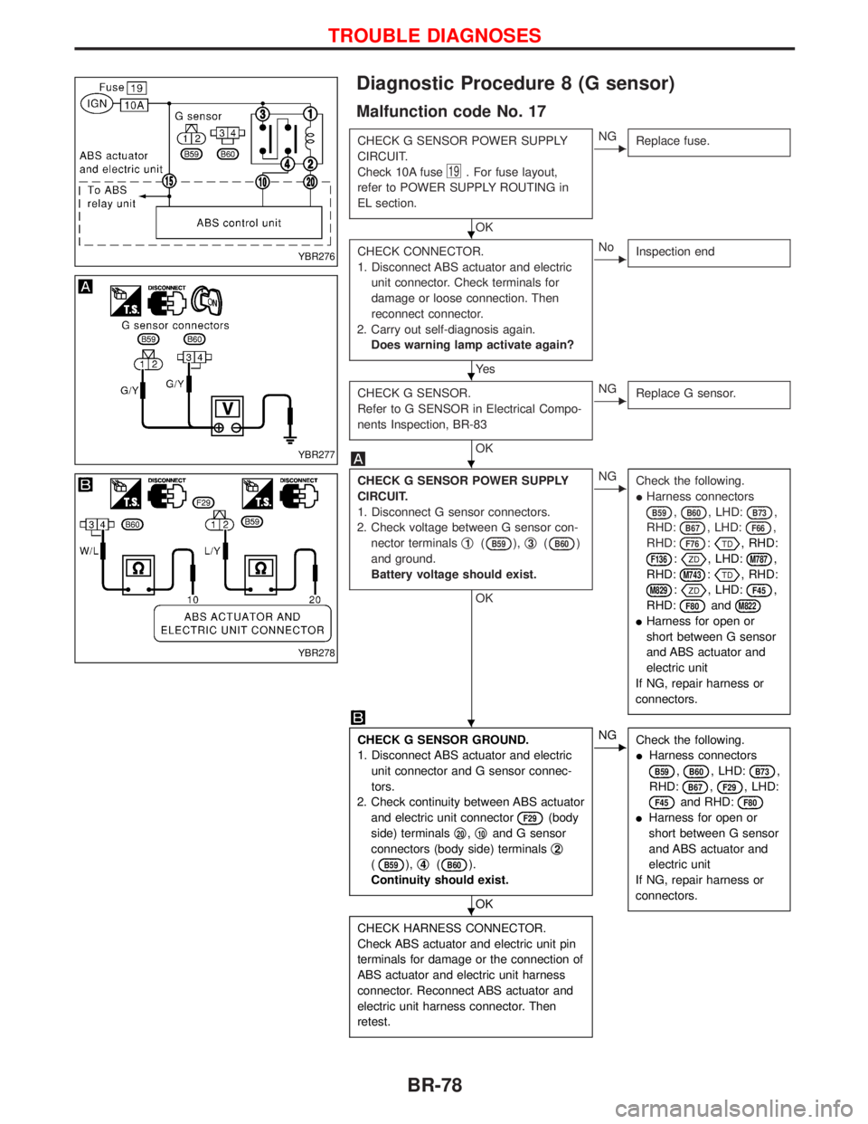
Malfunction code No. 17
CHECK G SENSOR POWER SUPPLY
CIRCUIT.
Check 10A fuse
19. For fuse layout,
refer to POWER SUPPLY ROUTING in
EL section.
OK
ENG
Replace fuse.
CHECK CONNECTOR.
1. Disconnect ABS actuator and electric
unit connector. Check terminals for
damage or loose connection. Then
reconnect connector.
2. Carry out self-diagnosis again.
Does warning lamp activate again?
Ye s
ENo
Inspection end
CHECK G SENSOR.
Refer to G SENSOR in Electrical Compo-
nents Inspection, BR-83
OK
ENG
Replace G sensor.
CHECK G SENSOR POWER SUPPLY
CIRCUIT.
1. Disconnect G sensor connectors.
2. Check voltage between G sensor con-
nector terminalsq
1(B59),q3(B60)
and ground.
Battery voltage should exist.
OK
ENG
Check the following.
IHarness connectors
B59,B60, LHD:B73,
RHD:
B67, LHD:F66,
RHD:
F76:, RHD:
F136:, LHD:M787,
RHD:
M743:, RHD:
M829:, LHD:F45,
RHD:
F80andM822
IHarness for open or
short between G sensor
and ABS actuator and
electric unit
If NG, repair harness or
connectors.
CHECK G SENSOR GROUND.
1. Disconnect ABS actuator and electric
unit connector and G sensor connec-
tors.
2. Check continuity between ABS actuator
and electric unit connector
F29(body
side) terminalsq
20,q10and G sensor
connectors (body side) terminalsq
2
(B59),q4(B60).
Continuity should exist.
OK
ENG
Check the following.
IHarness connectors
B59,B60, LHD:B73,
RHD:
B67,F29, LHD:
F45and RHD:F80
IHarness for open or
short between G sensor
and ABS actuator and
electric unit
If NG, repair harness or
connectors.
CHECK HARNESS CONNECTOR.
Check ABS actuator and electric unit pin
terminals for damage or the connection of
ABS actuator and electric unit harness
connector. Reconnect ABS actuator and
electric unit harness connector. Then
retest.
YBR276
YBR277
YBR278
H
H
H
H
H
TROUBLE DIAGNOSES
BR-78