Page 461 of 1767

Description
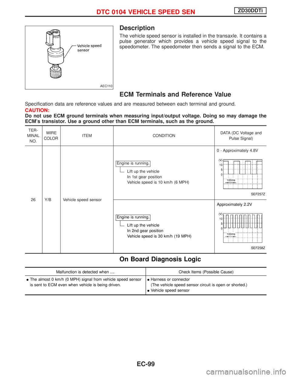
The vehicle speed sensor is installed in the transaxle. It contains a
pulse generator which provides a vehicle speed signal to the
speedometer. The speedometer then sends a signal to the ECM.
ECM Terminals and Reference Value
Specification data are reference values and are measured between each terminal and ground.
CAUTION:
Do not use ECM ground terminals when measuring input/output voltage. Doing so may damage the
ECM's transistor. Use a ground other than ECM terminals, such as the ground.
TER-
MINAL
NO.WIRE
COLORITEM CONDITIONDATA (DC Voltage and
Pulse Signal)
26 Y/B Vehicle speed sensorEngine is running.
Lift up the vehicle
In 1st gear position
Vehicle speed is 10 km/h (6 MPH)0 - Approximately 4.8V
SEF257Z
Engine is running.
Lift up the vehicle
In 2nd gear position
Vehicle speed is 30 km/h (19 MPH)Approximately 2.2V
SEF258Z
On Board Diagnosis Logic
Malfunction is detected when .... Check Items (Possible Cause)
IThe almost 0 km/h (0 MPH) signal from vehicle speed sensor
is sent to ECM even when vehicle is being driven.IHarness or connector
(The vehicle speed sensor circuit is open or shorted.)
IVehicle speed sensor
AEC110
DTC 0104 VEHICLE SPEED SENZD30DDTi
EC-99
Page 462 of 1767
Overall Function Check
Use this procedure to check the overall function of the vehicle
speed sensor circuit. During this check, a DTC might not be con-
firmed.
WITH CONSULT-II
1) Lift up the vehicle.
2) Start engine.
3) Read vehicle speed sensor signal in ªDATA MONITORº mode
with CONSULT-II.
The vehicle speed on CONSULT-II should be able to exceed
10 km/h (6 MPH) when rotating wheels with suitable gear
position.
4) If NG, go to ªDiagnostic Procedureº, EC-103.
WITHOUT CONSULT-II
1) Lift up the vehicle.
2) Start engine.
3) Rotate drive wheel by hand.
4) Check voltage between ECM terminal 26 and ground with
tester.
Voltage should vary between0-BATTERY VOLTAGE.
5) If NG, go to ªDiagnostic Procedureº, EC-103.
SEF864Y
SEF811R
DTC 0104 VEHICLE SPEED SENZD30DDTi
EC-100
Page 465 of 1767

Diagnostic Procedure
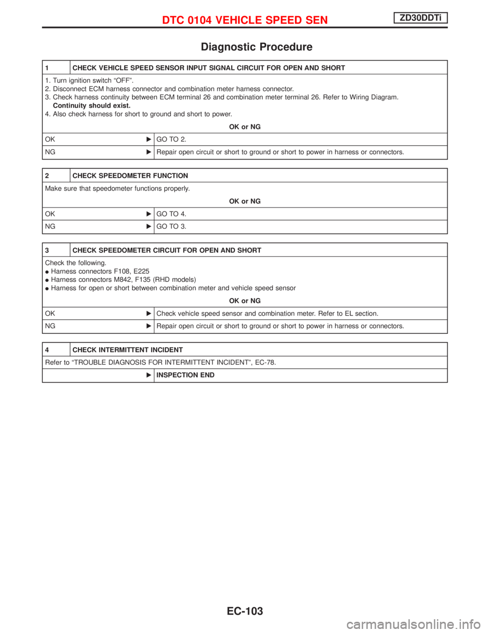
1 CHECK VEHICLE SPEED SENSOR INPUT SIGNAL CIRCUIT FOR OPEN AND SHORT
1. Turn ignition switch ªOFFº.
2. Disconnect ECM harness connector and combination meter harness connector.
3. Check harness continuity between ECM terminal 26 and combination meter terminal 26. Refer to Wiring Diagram.
Continuity should exist.
4. Also check harness for short to ground and short to power.
OK or NG
OKEGO TO 2.
NGERepair open circuit or short to ground or short to power in harness or connectors.
2 CHECK SPEEDOMETER FUNCTION
Make sure that speedometer functions properly.
OK or NG
OKEGO TO 4.
NGEGO TO 3.
3 CHECK SPEEDOMETER CIRCUIT FOR OPEN AND SHORT
Check the following.
IHarness connectors F108, E225
IHarness connectors M842, F135 (RHD models)
IHarness for open or short between combination meter and vehicle speed sensor
OK or NG
OKECheck vehicle speed sensor and combination meter. Refer to EL section.
NGERepair open circuit or short to ground or short to power in harness or connectors.
4 CHECK INTERMITTENT INCIDENT
Refer to ªTROUBLE DIAGNOSIS FOR INTERMITTENT INCIDENTº, EC-78.
EINSPECTION END
DTC 0104 VEHICLE SPEED SENZD30DDTi
EC-103
Page 471 of 1767
Description
SYSTEM DESCRIPTION
Sensor Input signal to ECM ECM function Actuator
Vehicle speed sensor Vehicle speed
Cooling fan con-
trolCooling fan relay Engine coolant temperature sensor Engine coolant temperature
Air conditioner switch Air conditioner ªONº signal
The ECM controls the cooling fan corresponding to the vehicle speed, engine coolant temperature, air condi-
tioner ON signal. The control system has 2-step control [ON/OFF].
OPERATION
CONSULT-II Reference Value in Data Monitor
Mode
Specification data are reference values.
MONITOR ITEM CONDITION SPECIFICATION
AIR COND SIGIEngine: After warming up, idle the
engineAir conditioner switch: OFF OFF
Air conditioner switch: ON
(Compressor operates.)ON
COOLING FANIWhen cooling fan is stopped. OFF
IWhen cooling fan operates. ON
SEF450Z
DTC 0208 OVER HEATZD30DDTi
EC-109
Page 472 of 1767

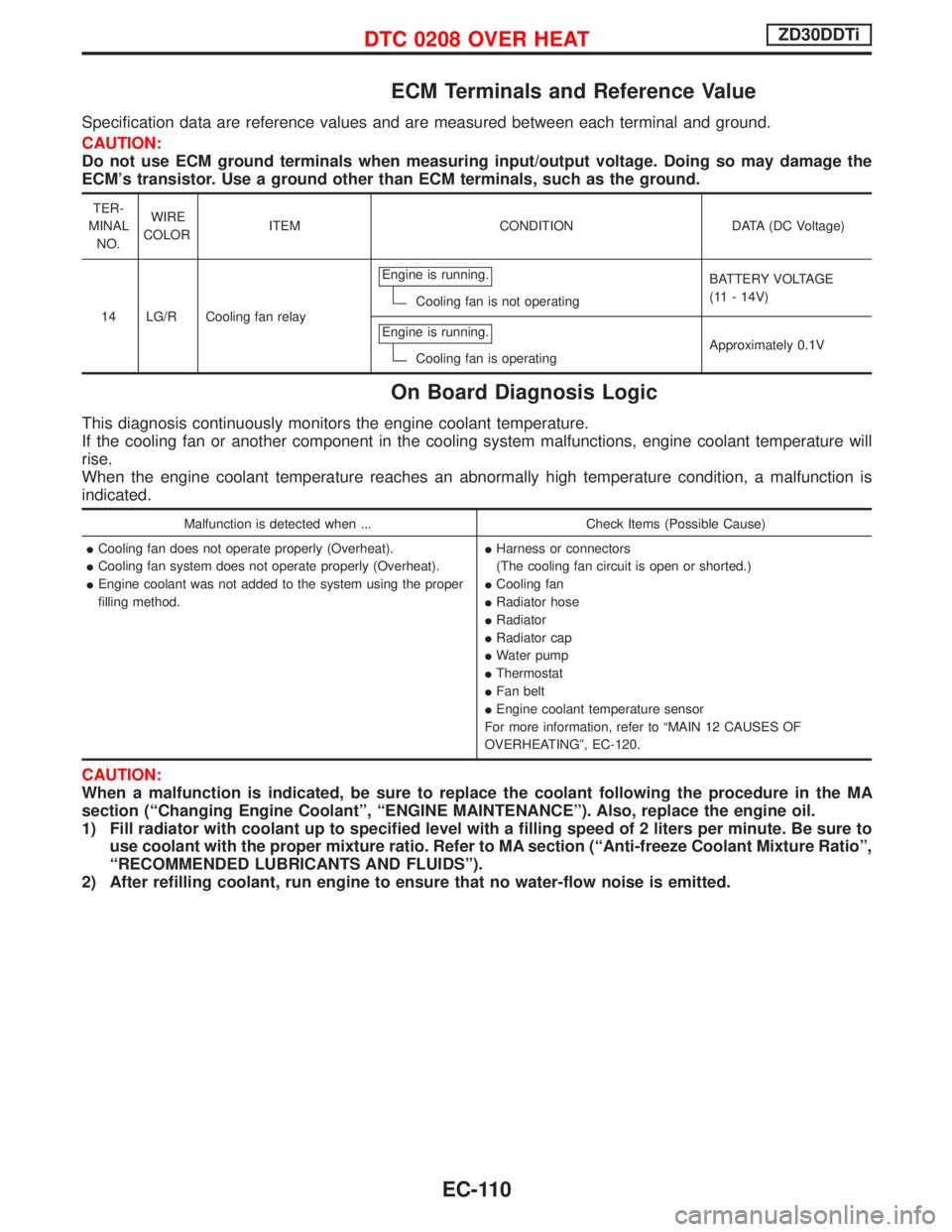
ECM Terminals and Reference Value
Specification data are reference values and are measured between each terminal and ground.
CAUTION:
Do not use ECM ground terminals when measuring input/output voltage. Doing so may damage the
ECM's transistor. Use a ground other than ECM terminals, such as the ground.
TER-
MINAL
NO.WIRE
COLORITEM CONDITION DATA (DC Voltage)
14 LG/R Cooling fan relayEngine is running.
Cooling fan is not operatingBATTERY VOLTAGE
(11 - 14V)
Engine is running.
Cooling fan is operatingApproximately 0.1V
On Board Diagnosis Logic
This diagnosis continuously monitors the engine coolant temperature.
If the cooling fan or another component in the cooling system malfunctions, engine coolant temperature will
rise.
When the engine coolant temperature reaches an abnormally high temperature condition, a malfunction is
indicated.
Malfunction is detected when ... Check Items (Possible Cause)
ICooling fan does not operate properly (Overheat).
ICooling fan system does not operate properly (Overheat).
IEngine coolant was not added to the system using the proper
filling method.IHarness or connectors
(The cooling fan circuit is open or shorted.)
ICooling fan
IRadiator hose
IRadiator
IRadiator cap
IWater pump
IThermostat
IFan belt
IEngine coolant temperature sensor
For more information, refer to ªMAIN 12 CAUSES OF
OVERHEATINGº, EC-120.
CAUTION:
When a malfunction is indicated, be sure to replace the coolant following the procedure in the MA
section (ªChanging Engine Coolantº, ªENGINE MAINTENANCEº). Also, replace the engine oil.
1) Fill radiator with coolant up to specified level with a filling speed of 2 liters per minute. Be sure to
use coolant with the proper mixture ratio. Refer to MA section (ªAnti-freeze Coolant Mixture Ratioº,
ªRECOMMENDED LUBRICANTS AND FLUIDSº).
2) After refilling coolant, run engine to ensure that no water-flow noise is emitted.
DTC 0208 OVER HEATZD30DDTi
EC-110
Page 473 of 1767

Overall Function Check
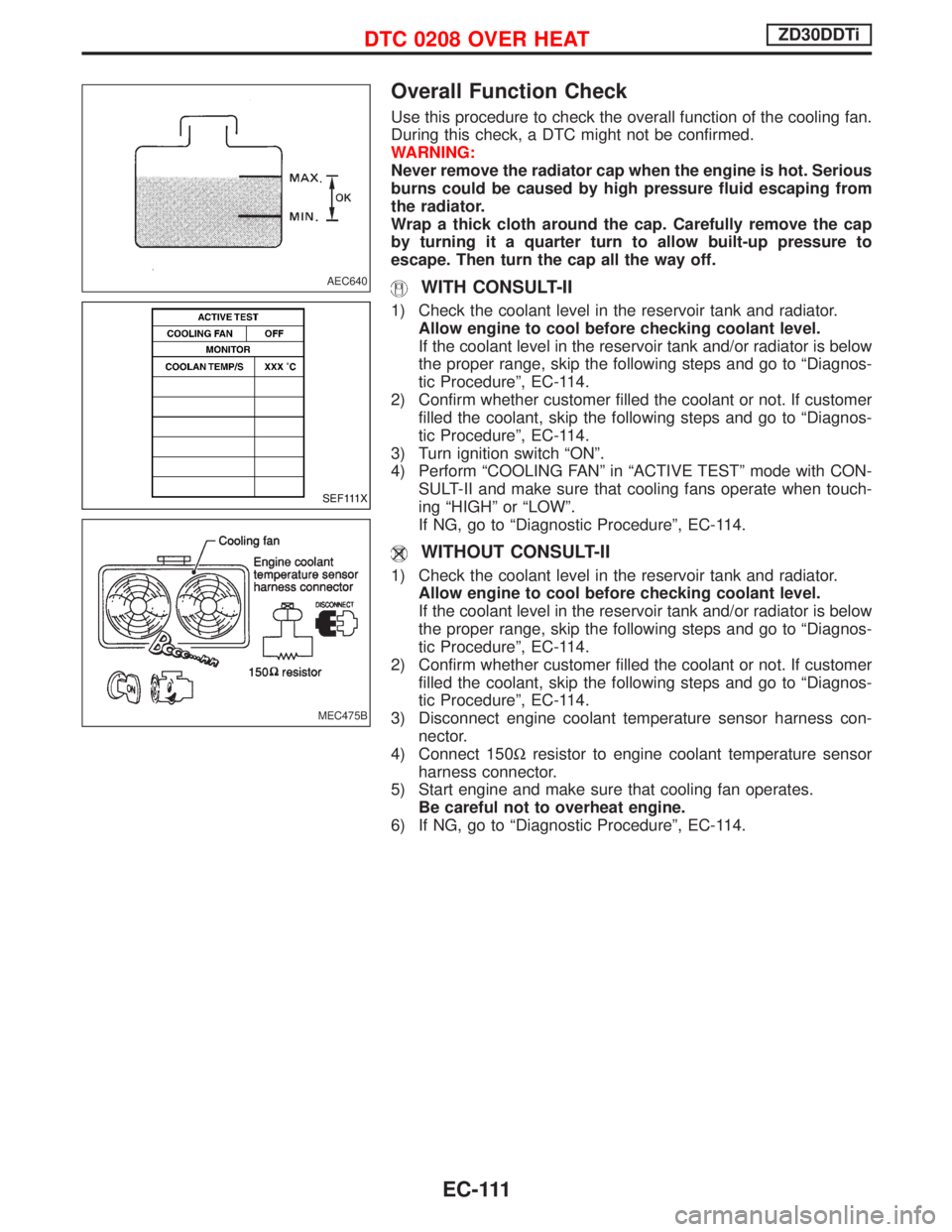
Use this procedure to check the overall function of the cooling fan.
During this check, a DTC might not be confirmed.
WARNING:
Never remove the radiator cap when the engine is hot. Serious
burns could be caused by high pressure fluid escaping from
the radiator.
Wrap a thick cloth around the cap. Carefully remove the cap
by turning it a quarter turn to allow built-up pressure to
escape. Then turn the cap all the way off.
WITH CONSULT-II
1) Check the coolant level in the reservoir tank and radiator.
Allow engine to cool before checking coolant level.
If the coolant level in the reservoir tank and/or radiator is below
the proper range, skip the following steps and go to ªDiagnos-
tic Procedureº, EC-114.
2) Confirm whether customer filled the coolant or not. If customer
filled the coolant, skip the following steps and go to ªDiagnos-
tic Procedureº, EC-114.
3) Turn ignition switch ªONº.
4) Perform ªCOOLING FANº in ªACTIVE TESTº mode with CON-
SULT-II and make sure that cooling fans operate when touch-
ing ªHIGHº or ªLOWº.
If NG, go to ªDiagnostic Procedureº, EC-114.
WITHOUT CONSULT-II
1) Check the coolant level in the reservoir tank and radiator.
Allow engine to cool before checking coolant level.
If the coolant level in the reservoir tank and/or radiator is below
the proper range, skip the following steps and go to ªDiagnos-
tic Procedureº, EC-114.
2) Confirm whether customer filled the coolant or not. If customer
filled the coolant, skip the following steps and go to ªDiagnos-
tic Procedureº, EC-114.
3) Disconnect engine coolant temperature sensor harness con-
nector.
4) Connect 150Wresistor to engine coolant temperature sensor
harness connector.
5) Start engine and make sure that cooling fan operates.
Be careful not to overheat engine.
6) If NG, go to ªDiagnostic Procedureº, EC-114.
AEC640
SEF111X
MEC475B
DTC 0208 OVER HEATZD30DDTi
EC-111
Page 476 of 1767
Diagnostic Procedure
1 INSPECTION START
Do you have CONSULT-II?
YesorNo
Ye sEGO TO 2.
NoEGO TO 3.
2 CHECK COOLING FAN OPERATION
With CONSULT-II
1. Turn ignition switch ªONº.
2. Perform ªCOOLING FANº in ªACTIVE TESTº mode with CONSULT-II.
SEF646X
3. Make sure that cooling fan operates.
OK or NG
OKEGO TO 12.
NGEGO TO 4.
3 CHECK COOLING FAN OPERATION
Without CONSULT-II
1. Turn ignition switch ªOFFº.
2. Disconnect engine coolant temperature sensor harness connector.
3. Connect 150Wresistor to engine coolant temperature sensor harness connector.
4. Restart engine and make sure that cooling fan operates.
MEC475B
OK or NG
OKEGO TO 12.
NGEGO TO 4.
DTC 0208 OVER HEATZD30DDTi
EC-114
Page 481 of 1767
16 CHECK THERMOSTAT
1. Remove thermostat.
2. Check valve seating condition at normal room temperatures.
It should seat tightly.
3. Check valve opening temperature and valve lift.
SLC343
Valve opening temperature:
82ÉC (180ÉF) [standard] (Models for cold areas)
76.5ÉC (170ÉF) [standard] (Models for except cold areas)
Valve lift:
More than 10 mm/95ÉC (0.394 in/203ÉF)
4. Check if valve is closed at 5ÉC (9ÉF) below valve opening temperature. For details, refer to LC section, ªThermostatº.
OK or NG
OKEGO TO 17.
NGEReplace thermostat.
17 CHECK ENGINE COOLANT TEMPERATURE SENSOR
1. Remove engine coolant temperature sensor.
2. Check resistance between engine coolant temperature sensor terminals 1 and 2 as shown in the figure.
SEF304X
OK or NG
OKEGO TO 18.
NGEReplace engine coolant temperature sensor.
DTC 0208 OVER HEATZD30DDTi
Diagnostic Procedure (Cont'd)
EC-119