2002 NISSAN TERRANO torque
[x] Cancel search: torquePage 1140 of 1767
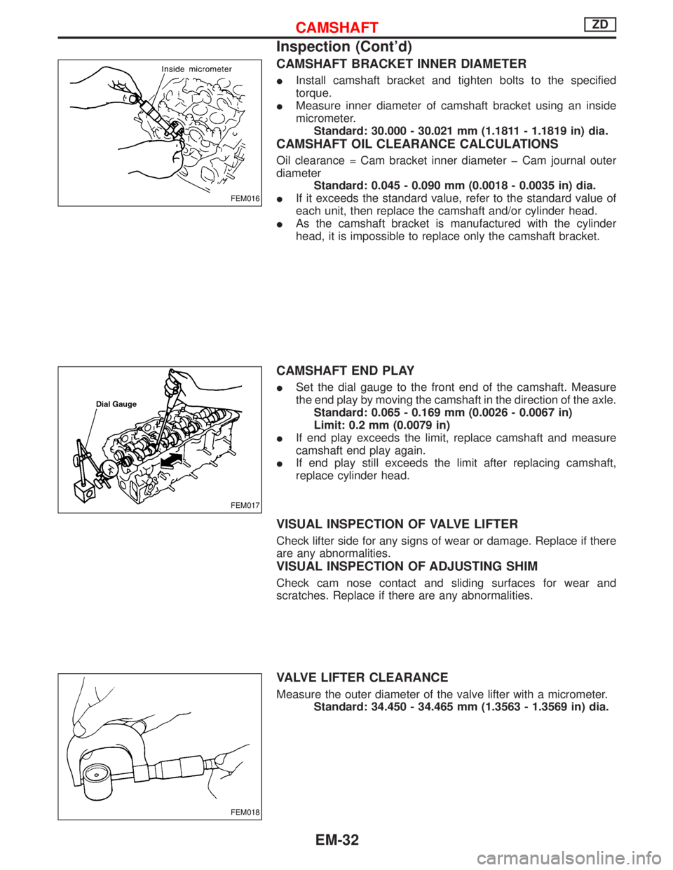
CAMSHAFT BRACKET INNER DIAMETER
IInstall camshaft bracket and tighten bolts to the specified
torque.
IMeasure inner diameter of camshaft bracket using an inside
micrometer.
Standard: 30.000 - 30.021 mm (1.1811 - 1.1819 in) dia.
CAMSHAFT OIL CLEARANCE CALCULATIONS
Oil clearance = Cam bracket inner diameter þ Cam journal outer
diameter
Standard: 0.045 - 0.090 mm (0.0018 - 0.0035 in) dia.
IIf it exceeds the standard value, refer to the standard value of
each unit, then replace the camshaft and/or cylinder head.
IAs the camshaft bracket is manufactured with the cylinder
head, it is impossible to replace only the camshaft bracket.
CAMSHAFT END PLAY
ISet the dial gauge to the front end of the camshaft. Measure
the end play by moving the camshaft in the direction of the axle.
Standard: 0.065 - 0.169 mm (0.0026 - 0.0067 in)
Limit: 0.2 mm (0.0079 in)
IIf end play exceeds the limit, replace camshaft and measure
camshaft end play again.
IIf end play still exceeds the limit after replacing camshaft,
replace cylinder head.
VISUAL INSPECTION OF VALVE LIFTER
Check lifter side for any signs of wear or damage. Replace if there
are any abnormalities.
VISUAL INSPECTION OF ADJUSTING SHIM
Check cam nose contact and sliding surfaces for wear and
scratches. Replace if there are any abnormalities.
VALVE LIFTER CLEARANCE
Measure the outer diameter of the valve lifter with a micrometer.
Standard: 34.450 - 34.465 mm (1.3563 - 1.3569 in) dia.
FEM016
FEM017
FEM018
CAMSHAFTZD
Inspection (Cont'd)
EM-32
Page 1161 of 1767
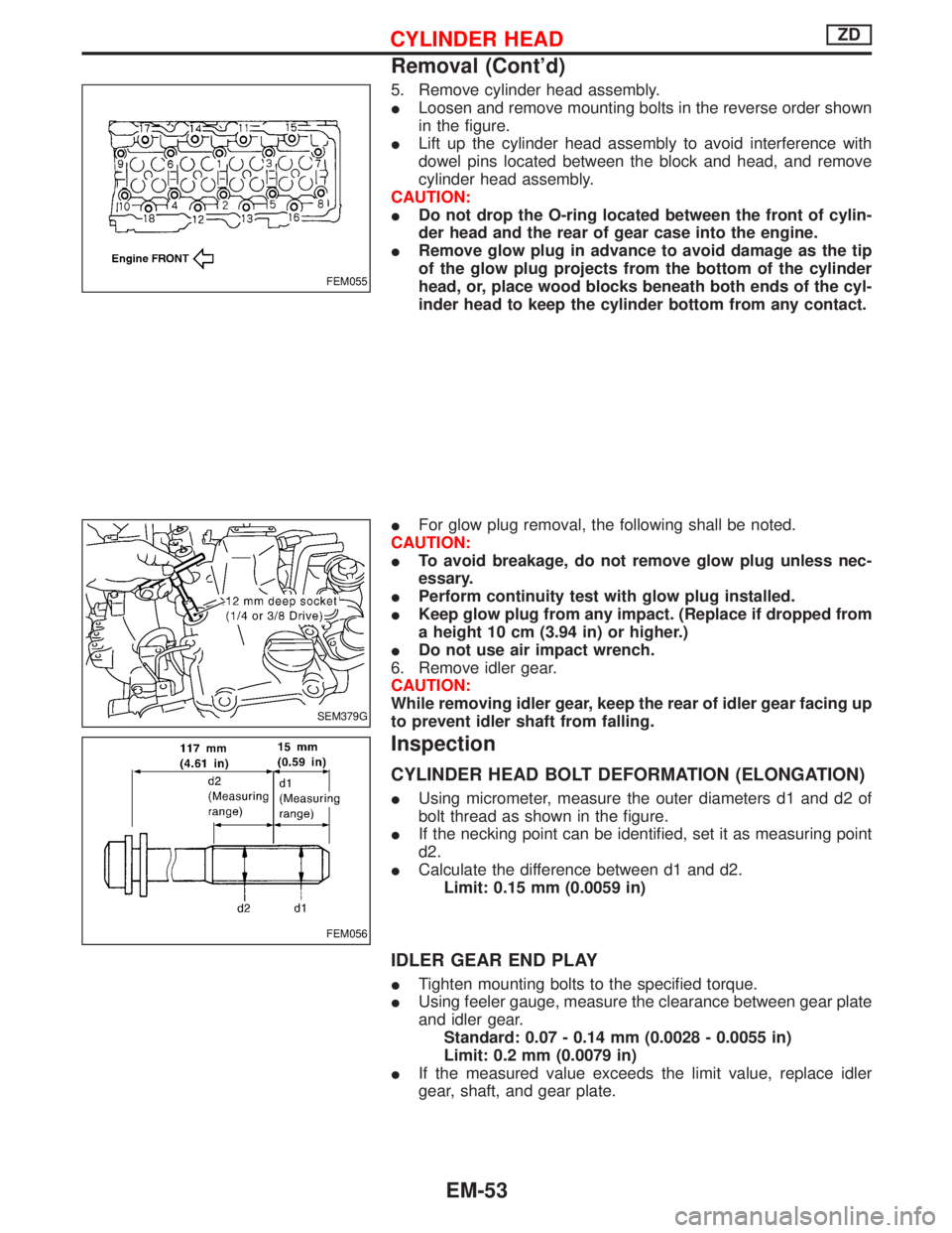
5. Remove cylinder head assembly.
ILoosen and remove mounting bolts in the reverse order shown
in the figure.
ILift up the cylinder head assembly to avoid interference with
dowel pins located between the block and head, and remove
cylinder head assembly.
CAUTION:
IDo not drop the O-ring located between the front of cylin-
der head and the rear of gear case into the engine.
IRemove glow plug in advance to avoid damage as the tip
of the glow plug projects from the bottom of the cylinder
head, or, place wood blocks beneath both ends of the cyl-
inder head to keep the cylinder bottom from any contact.
IFor glow plug removal, the following shall be noted.
CAUTION:
ITo avoid breakage, do not remove glow plug unless nec-
essary.
IPerform continuity test with glow plug installed.
IKeep glow plug from any impact. (Replace if dropped from
a height 10 cm (3.94 in) or higher.)
IDo not use air impact wrench.
6. Remove idler gear.
CAUTION:
While removing idler gear, keep the rear of idler gear facing up
to prevent idler shaft from falling.
Inspection
CYLINDER HEAD BOLT DEFORMATION (ELONGATION)
IUsing micrometer, measure the outer diameters d1 and d2 of
bolt thread as shown in the figure.
IIf the necking point can be identified, set it as measuring point
d2.
ICalculate the difference between d1 and d2.
Limit: 0.15 mm (0.0059 in)
IDLER GEAR END PLAY
ITighten mounting bolts to the specified torque.
IUsing feeler gauge, measure the clearance between gear plate
and idler gear.
Standard: 0.07 - 0.14 mm (0.0028 - 0.0055 in)
Limit: 0.2 mm (0.0079 in)
IIf the measured value exceeds the limit value, replace idler
gear, shaft, and gear plate.
FEM055
SEM379G
FEM056
CYLINDER HEADZD
Removal (Cont'd)
EM-53
Page 1163 of 1767
Unit: mm (in)
GradePiston crown
depressionGasket thick-
ness*1No. of notches
1Less than þ0.078
(þ0.0031)*20.65 (0.0256) 1
2More than þ0.078
(þ0.0031)*30.70 (0.0276) 2
*1: Thickness of gasket tightened with head bolts
*2: Indicates values such as þ0.080 mm (þ0.0031 in).
*3: Indicates values such as þ0.075 mm (þ0.0030 in).
2. Install idler gear and idler shaft.
ICheck that the counter marks with cam gear, ªAAº and ªBBº, are
located on the front side of the engine.
Refer to EM-52.
CAUTION:
Since idler gear cannot be installed or removed with cylinder
head assembly mounted on the engine because of interfer-
ence with gear case, make sure that there are no reverse
installations or uninstalled parts.
3. Install cylinder head assembly.
1) Attach gasket onto the rear of gear case.
2) Install O-ring to the rear of gear case.
3) Align cylinder head assembly with dowel pin of cylinder block
and install.
CAUTION:
IMake sure the O-ring does not fall off. Be careful not to
drop the O-ring.
IDo not damage gasket located at the front.
4. Position cylinder head assembly close to the rear of the gear
case.
1) Install cylinder head bolts to the front and rear of cylinder head
respectively, and tighten to the specified torque.
:40-49N×m (4.0 - 5.0 kg-m, 29 - 36 ft-lb)
2) Loosen cylinder head bolts completely.
3) Install gear case mounting bolts to 2 positions shown by arrows
in the figure, and tighten to the specified torque.
: Less than 9.8 N×m (1.0 kg-m, 87 in-lb)
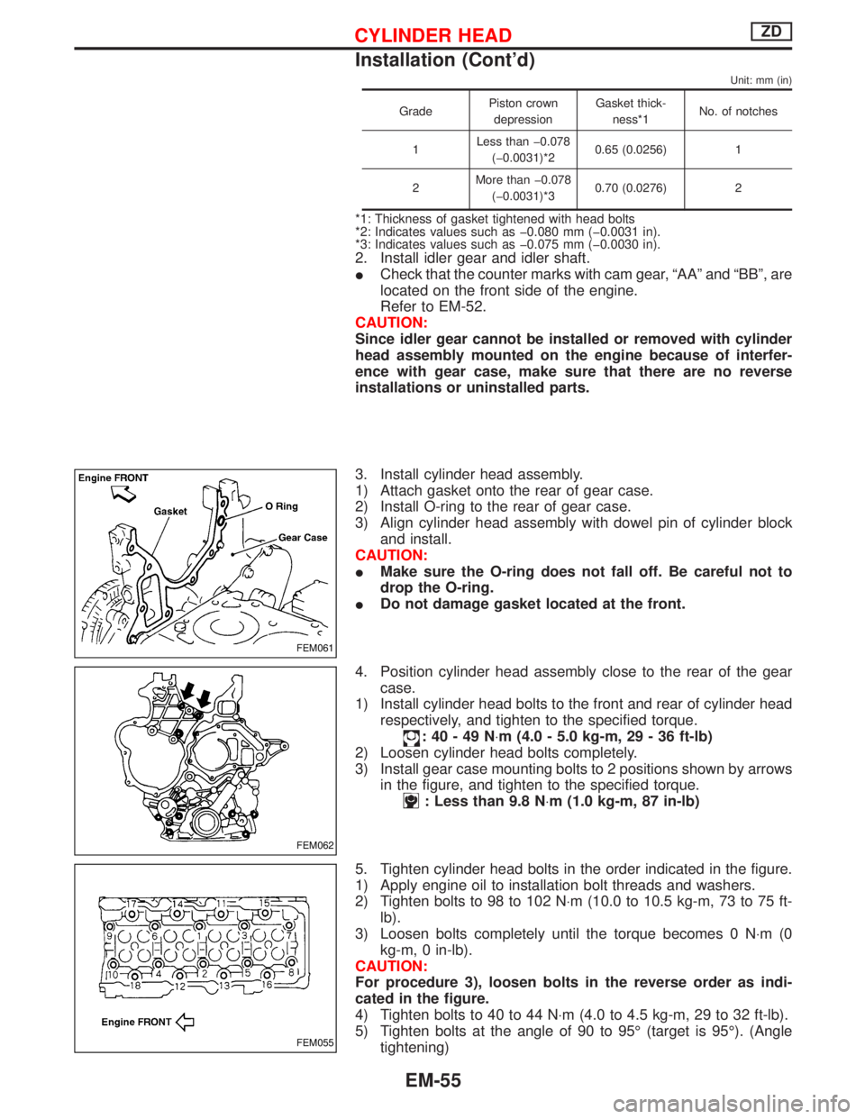
5. Tighten cylinder head bolts in the order indicated in the figure.
1) Apply engine oil to installation bolt threads and washers.
2) Tighten bolts to 98 to 102 N×m (10.0 to 10.5 kg-m, 73 to 75 ft-
lb).
3) Loosen bolts completely until the torque becomes 0 N×m(0
kg-m, 0 in-lb).
CAUTION:
For procedure 3), loosen bolts in the reverse order as indi-
cated in the figure.
4) Tighten bolts to 40 to 44 N×m (4.0 to 4.5 kg-m, 29 to 32 ft-lb).
5) Tighten bolts at the angle of 90 to 95É (target is 95É). (Angle
tightening)
FEM061
FEM062
FEM055
CYLINDER HEADZD
Installation (Cont'd)
EM-55
Page 1164 of 1767
6) Once again, tighten bolts at the angle of 90 to 95É (target is
95É). (Angle tightening)
CAUTION:
Perform the following procedure to check turning angle of
angle tightening, and do not judge by visual check.
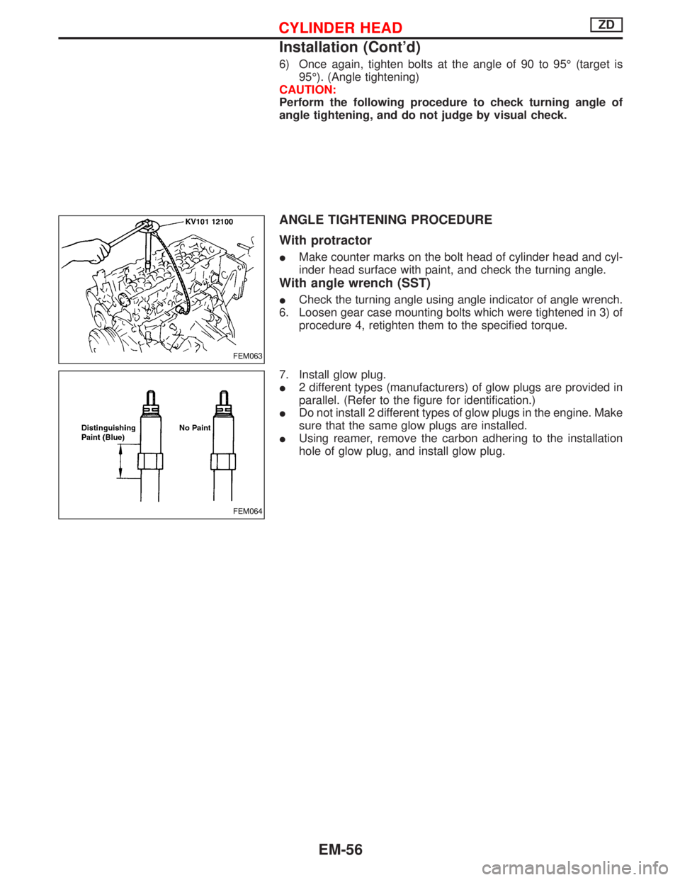
ANGLE TIGHTENING PROCEDURE
With protractor
IMake counter marks on the bolt head of cylinder head and cyl-
inder head surface with paint, and check the turning angle.
With angle wrench (SST)
ICheck the turning angle using angle indicator of angle wrench.
6. Loosen gear case mounting bolts which were tightened in 3) of
procedure 4, retighten them to the specified torque.
7. Install glow plug.
I2 different types (manufacturers) of glow plugs are provided in
parallel. (Refer to the figure for identification.)
IDo not install 2 different types of glow plugs in the engine. Make
sure that the same glow plugs are installed.
IUsing reamer, remove the carbon adhering to the installation
hole of glow plug, and install glow plug.
FEM063
FEM064
CYLINDER HEADZD
Installation (Cont'd)
EM-56
Page 1172 of 1767
Engine room (Left)
3. Remove air duct and air cleaner case.
4. Disconnect vacuum hose to the vehicle on the engine.
5. Disconnect harness connectors from alternator and air com-
pressor.
6. Remove alternator.
7. After removing refrigerant, remove pipes of air compressor and
inlet/outlet.
8. Disconnect heating hose, install blank cap to hose to prevent
coolant from leaking.
9. Remove heating pipe.
10. Remove heat insulator.
11. Remove catalytic converter.
Engine room (Right)
12. Remove power steering reservoir tank from bracket, and fix it
to the vehicle with a rope.
CAUTION:
Keep the reservoir tank level when fixing to prevent oil leak.
13. Remove fuel feed and return hoses.
CAUTION:
Install blank caps immediately to avoid fuel leakage.
14. Remove all harness connectors on the engine, and move har-
nesses to the side of the vehicle.
Vehicle underfloor
15. Remove starter motor.
16. Detach A/T oil cooler pipes from oil pan. (A/T model)
17. Remove rear propeller shaft.
18. Remove mounting bolts to secure the engine to transmission.
1) Remove torque converter installation bolt. (A/T model)
2) Lift transmission bottom with transmission jack, and remove
rear mount members from the vehicle.
3) Lower transmission with the jack, and remove upper mounting
bolts securing the engine to transmission.
4) Lift transmission with the jack, and reinstall rear mount mem-
bers to the vehicle.
5) Position the jack to the front side of transmission.
6) Remove remaining mounting bolts securing the engine to trans-
mission.
Removal operation
19. Remove air conditioner high pressure pipes at the rear of the
engine room.
IThis is due to some inconvenience in the rear slinger installa-
tion.
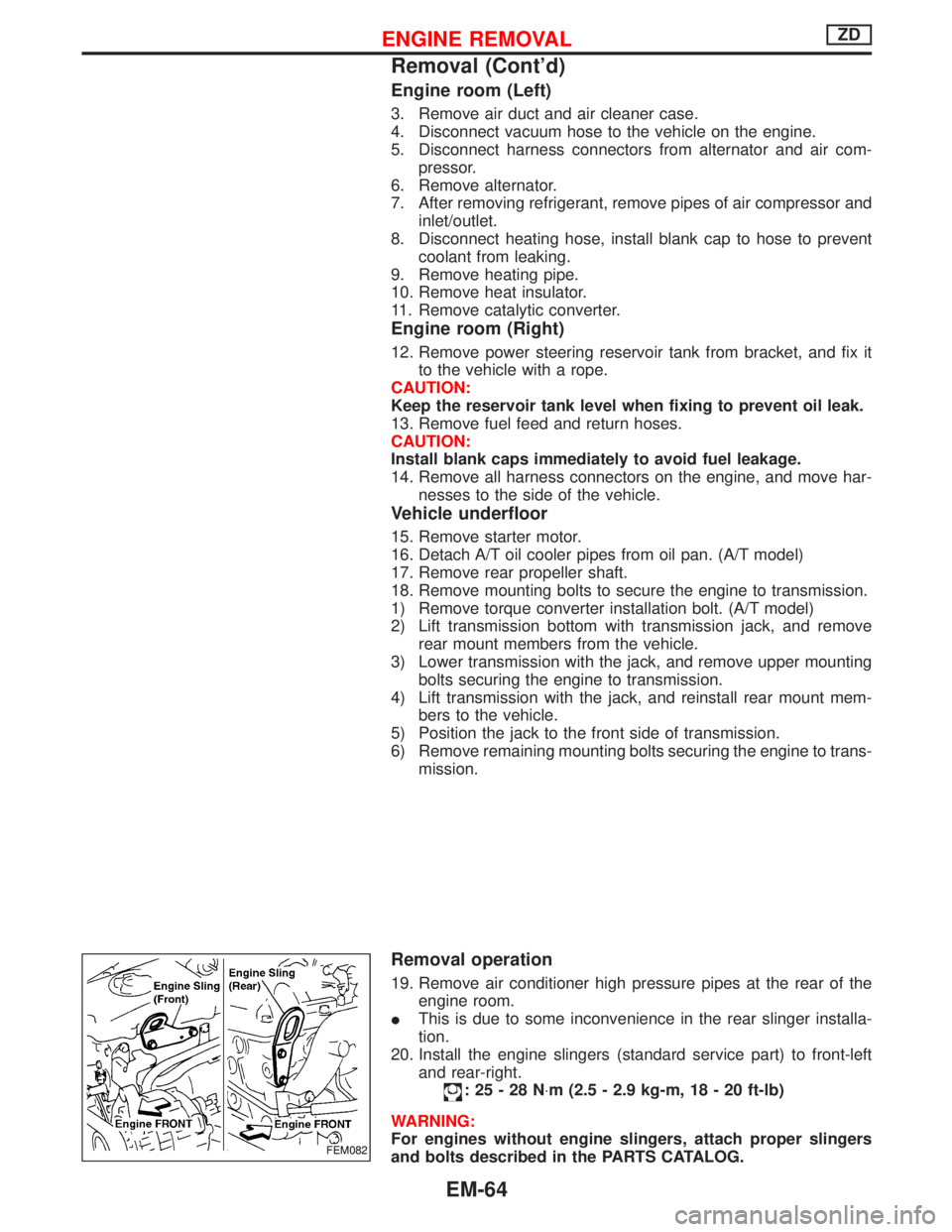
20. Install the engine slingers (standard service part) to front-left
and rear-right.
:25-28N×m (2.5 - 2.9 kg-m, 18 - 20 ft-lb)
WARNING:
For engines without engine slingers, attach proper slingers
and bolts described in the PARTS CATALOG.
FEM082
ENGINE REMOVALZD
Removal (Cont'd)
EM-64
Page 1181 of 1767
CONNECTING ROD BEND AND TORSION
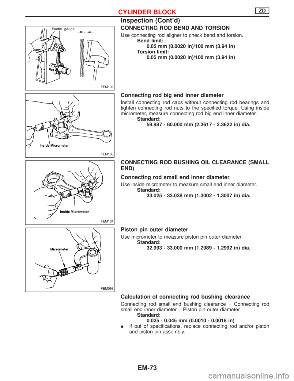
Use connecting rod aligner to check bend and torsion.
Bend limit:
0.05 mm (0.0020 in)/100 mm (3.94 in)
Torsion limit:
0.05 mm (0.0020 in)/100 mm (3.94 in)
Connecting rod big end inner diameter
Install connecting rod caps without connecting rod bearings and
tighten connecting rod nuts to the specified torque. Using inside
micrometer, measure connecting rod big end inner diameter.
Standard:
59.987 - 60.000 mm (2.3617 - 2.3622 in) dia.
CONNECTING ROD BUSHING OIL CLEARANCE (SMALL
END)
Connecting rod small end inner diameter
Use inside micrometer to measure small end inner diameter.
Standard:
33.025 - 33.038 mm (1.3002 - 1.3007 in) dia.
Piston pin outer diameter
Use micrometer to measure piston pin outer diameter.
Standard:
32.993 - 33.000 mm (1.2989 - 1.2992 in) dia.
Calculation of connecting rod bushing clearance
Connecting rod small end bushing clearance = Connecting rod
small end inner diameter þ Piston pin outer diameter
Standard:
0.025 - 0.045 mm (0.0010 - 0.0018 in)
IIf out of specifications, replace connecting rod and/or piston
and piston pin assembly.
FEM102
FEM103
FEM104
FEM098
CYLINDER BLOCKZD
Inspection (Cont'd)
EM-73
Page 1182 of 1767
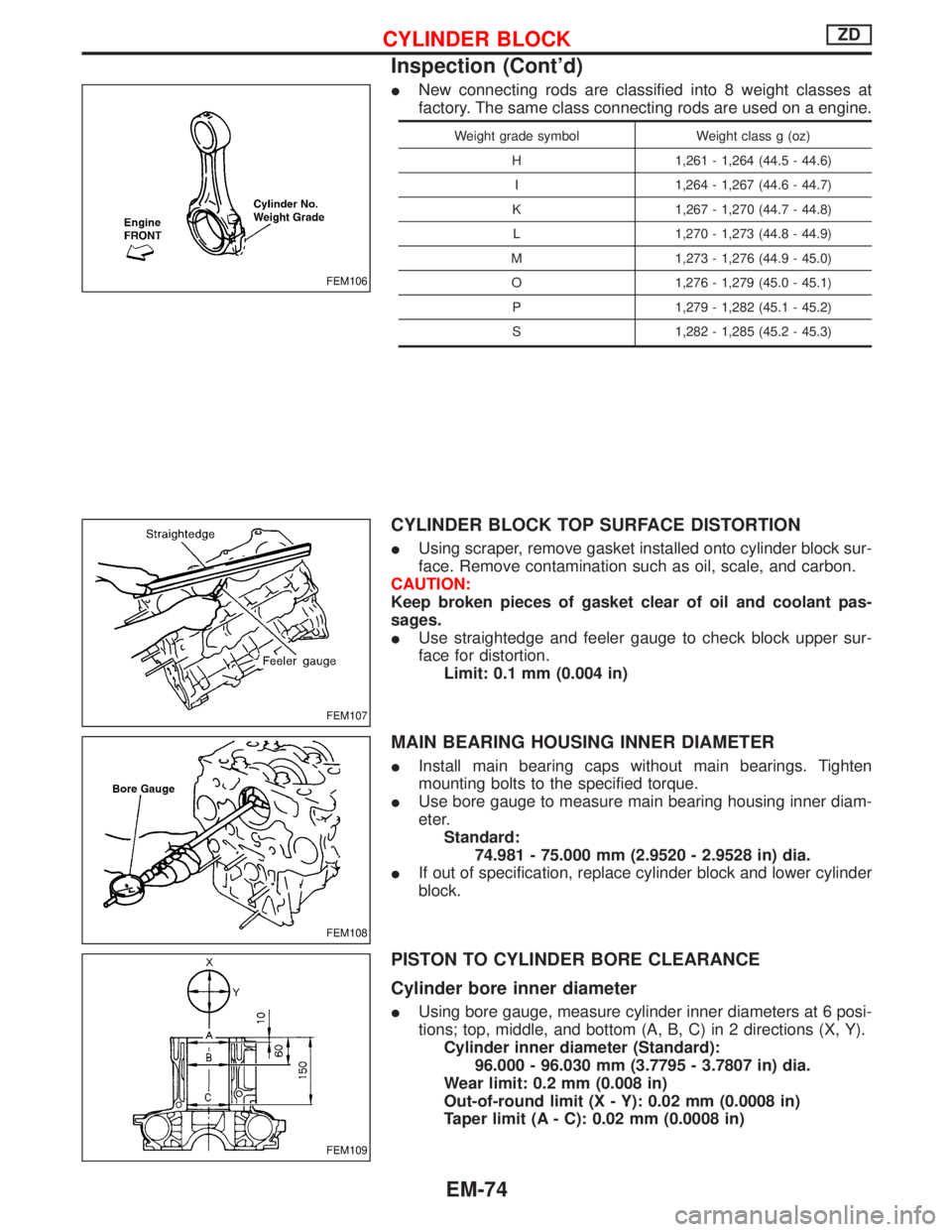
INew connecting rods are classified into 8 weight classes at
factory. The same class connecting rods are used on a engine.
Weight grade symbol Weight class g (oz)
H 1,261 - 1,264 (44.5 - 44.6)
I 1,264 - 1,267 (44.6 - 44.7)
K 1,267 - 1,270 (44.7 - 44.8)
L 1,270 - 1,273 (44.8 - 44.9)
M 1,273 - 1,276 (44.9 - 45.0)
O 1,276 - 1,279 (45.0 - 45.1)
P 1,279 - 1,282 (45.1 - 45.2)
S 1,282 - 1,285 (45.2 - 45.3)
CYLINDER BLOCK TOP SURFACE DISTORTION
IUsing scraper, remove gasket installed onto cylinder block sur-
face. Remove contamination such as oil, scale, and carbon.
CAUTION:
Keep broken pieces of gasket clear of oil and coolant pas-
sages.
IUse straightedge and feeler gauge to check block upper sur-
face for distortion.
Limit: 0.1 mm (0.004 in)
MAIN BEARING HOUSING INNER DIAMETER
IInstall main bearing caps without main bearings. Tighten
mounting bolts to the specified torque.
IUse bore gauge to measure main bearing housing inner diam-
eter.
Standard:
74.981 - 75.000 mm (2.9520 - 2.9528 in) dia.
IIf out of specification, replace cylinder block and lower cylinder
block.
PISTON TO CYLINDER BORE CLEARANCE
Cylinder bore inner diameter
IUsing bore gauge, measure cylinder inner diameters at 6 posi-
tions; top, middle, and bottom (A, B, C) in 2 directions (X, Y).
Cylinder inner diameter (Standard):
96.000 - 96.030 mm (3.7795 - 3.7807 in) dia.
Wear limit: 0.2 mm (0.008 in)
Out-of-round limit (X - Y): 0.02 mm (0.0008 in)
Taper limit (A - C): 0.02 mm (0.0008 in)
FEM106
FEM107
FEM108
FEM109
CYLINDER BLOCKZD
Inspection (Cont'd)
EM-74
Page 1185 of 1767
CONNECTING ROD BEARING OIL CLEARANCE
Method by measurement
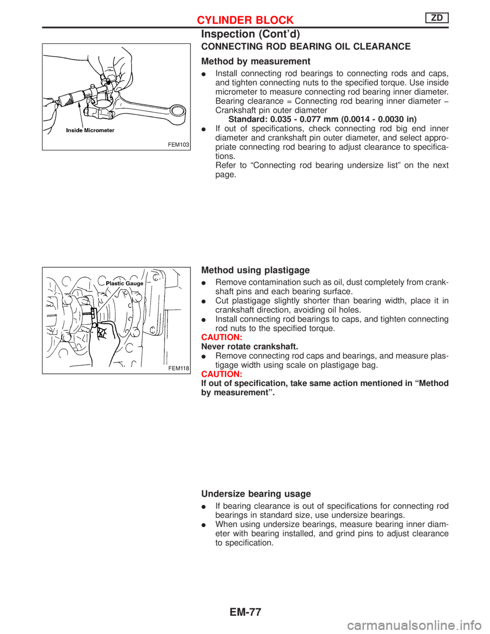
IInstall connecting rod bearings to connecting rods and caps,
and tighten connecting nuts to the specified torque. Use inside
micrometer to measure connecting rod bearing inner diameter.
Bearing clearance = Connecting rod bearing inner diameter þ
Crankshaft pin outer diameter
Standard: 0.035 - 0.077 mm (0.0014 - 0.0030 in)
IIf out of specifications, check connecting rod big end inner
diameter and crankshaft pin outer diameter, and select appro-
priate connecting rod bearing to adjust clearance to specifica-
tions.
Refer to ªConnecting rod bearing undersize listº on the next
page.
Method using plastigage
IRemove contamination such as oil, dust completely from crank-
shaft pins and each bearing surface.
ICut plastigage slightly shorter than bearing width, place it in
crankshaft direction, avoiding oil holes.
IInstall connecting rod bearings to caps, and tighten connecting
rod nuts to the specified torque.
CAUTION:
Never rotate crankshaft.
IRemove connecting rod caps and bearings, and measure plas-
tigage width using scale on plastigage bag.
CAUTION:
If out of specification, take same action mentioned in ªMethod
by measurementº.
Undersize bearing usage
IIf bearing clearance is out of specifications for connecting rod
bearings in standard size, use undersize bearings.
IWhen using undersize bearings, measure bearing inner diam-
eter with bearing installed, and grind pins to adjust clearance
to specification.
FEM103
FEM118
CYLINDER BLOCKZD
Inspection (Cont'd)
EM-77