Page 116 of 1767
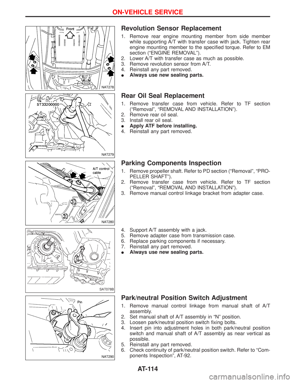
Revolution Sensor Replacement
1. Remove rear engine mounting member from side member
while supporting A/T with transfer case with jack. Tighten rear
engine mounting member to the specified torque. Refer to EM
section (ªENGINE REMOVALº).
2. Lower A/T with transfer case as much as possible.
3. Remove revolution sensor from A/T.
4. Reinstall any part removed.
IAlways use new sealing parts.
Rear Oil Seal Replacement
1. Remove transfer case from vehicle. Refer to TF section
(ªRemovalº, ªREMOVAL AND INSTALLATIONº).
2. Remove rear oil seal.
3. Install rear oil seal.
IApply ATF before installing.
4. Reinstall any part removed.
Parking Components Inspection
1. Remove propeller shaft. Refer to PD section (ªRemovalº, ªPRO-
PELLER SHAFTº).
2. Remove transfer case from vehicle. Refer to TF section
(ªRemovalº, ªREMOVAL AND INSTALLATIONº).
3. Remove manual control linkage bracket from adapter case.
4. Support A/T assembly with a jack.
5. Remove adapter case from transmission case.
6. Replace parking components if necessary.
7. Reinstall any part removed.
IAlways use new sealing parts.
Park/neutral Position Switch Adjustment
1. Remove manual control linkage from manual shaft of A/T
assembly.
2. Set manual shaft of A/T assembly in ªNº position.
3. Loosen park/neutral position switch fixing bolts.
4. Insert pin into adjustment holes in both park/neutral position
switch and manual shaft of A/T assembly as near vertical as
possible.
5. Reinstall any part removed.
6. Check continuity of park/neutral position switch. Refer to ªCom-
ponents Inspectionº, AT-92.
NAT278
NAT279
NAT280
SAT078B
NAT290
ON-VEHICLE SERVICE
AT-114
Page 117 of 1767
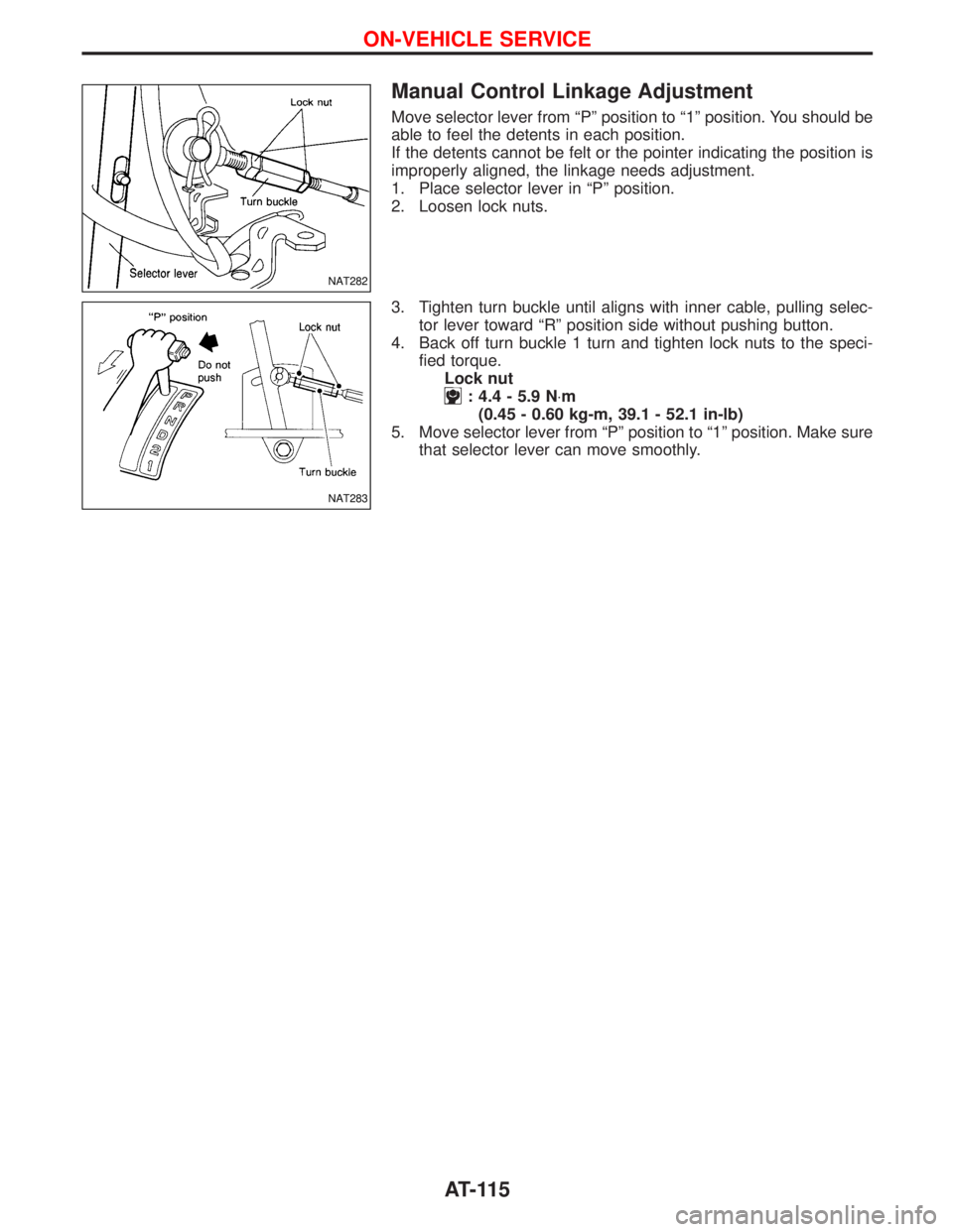
Manual Control Linkage Adjustment
Move selector lever from ªPº position to ª1º position. You should be
able to feel the detents in each position.
If the detents cannot be felt or the pointer indicating the position is
improperly aligned, the linkage needs adjustment.
1. Place selector lever in ªPº position.
2. Loosen lock nuts.
3. Tighten turn buckle until aligns with inner cable, pulling selec-
tor lever toward ªRº position side without pushing button.
4. Back off turn buckle 1 turn and tighten lock nuts to the speci-
fied torque.
Lock nut
: 4.4 - 5.9 N×m
(0.45 - 0.60 kg-m, 39.1 - 52.1 in-lb)
5. Move selector lever from ªPº position to ª1º position. Make sure
that selector lever can move smoothly.
NAT282
NAT283
ON-VEHICLE SERVICE
AT-115
Page 119 of 1767
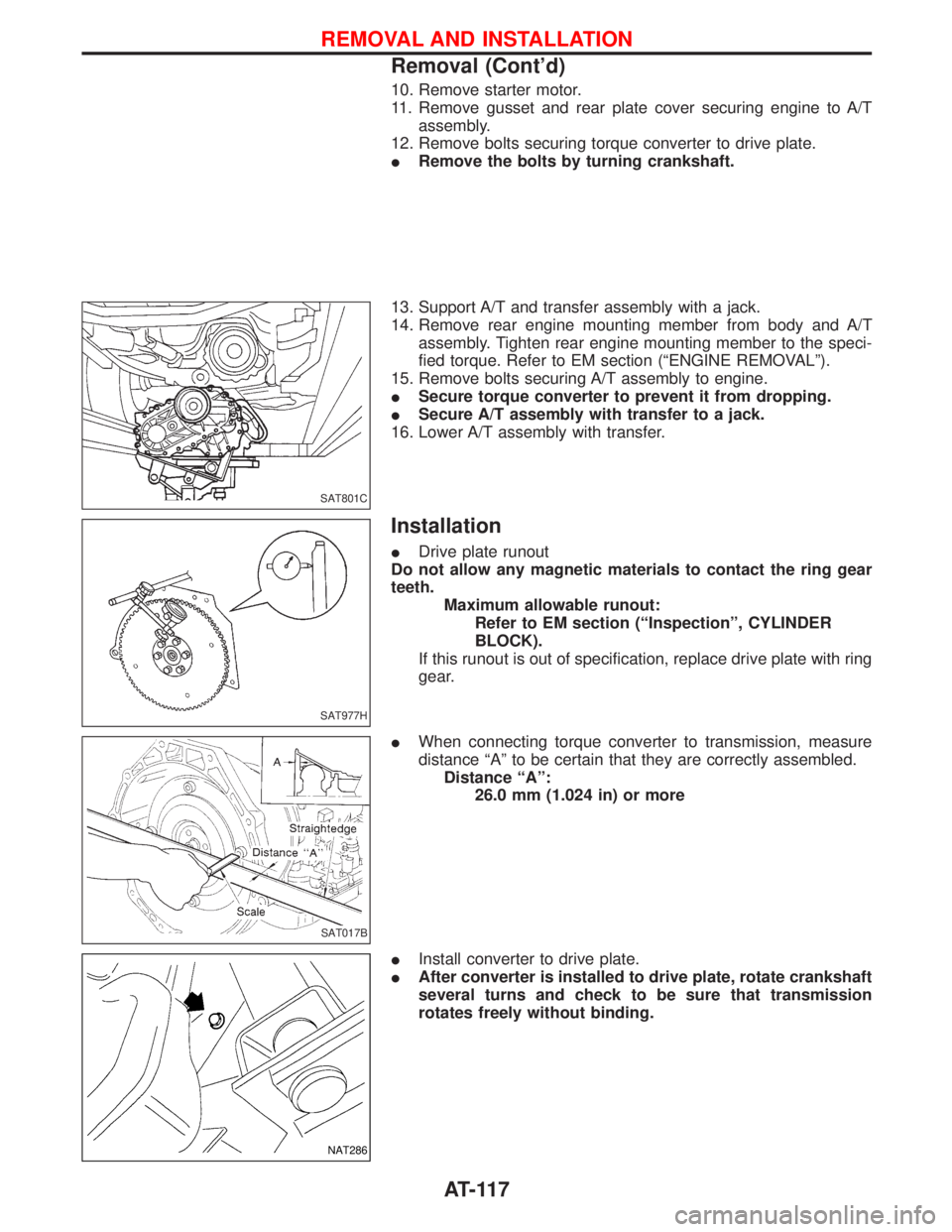
10. Remove starter motor.
11. Remove gusset and rear plate cover securing engine to A/T
assembly.
12. Remove bolts securing torque converter to drive plate.
IRemove the bolts by turning crankshaft.
13. Support A/T and transfer assembly with a jack.
14. Remove rear engine mounting member from body and A/T
assembly. Tighten rear engine mounting member to the speci-
fied torque. Refer to EM section (ªENGINE REMOVALº).
15. Remove bolts securing A/T assembly to engine.
ISecure torque converter to prevent it from dropping.
ISecure A/T assembly with transfer to a jack.
16. Lower A/T assembly with transfer.
Installation
IDrive plate runout
Do not allow any magnetic materials to contact the ring gear
teeth.
Maximum allowable runout:
Refer to EM section (ªInspectionº, CYLINDER
BLOCK).
If this runout is out of specification, replace drive plate with ring
gear.
IWhen connecting torque converter to transmission, measure
distance ªAº to be certain that they are correctly assembled.
Distance ªAº:
26.0 mm (1.024 in) or more
IInstall converter to drive plate.
IAfter converter is installed to drive plate, rotate crankshaft
several turns and check to be sure that transmission
rotates freely without binding.
SAT801C
SAT977H
SAT017B
NAT286
REMOVAL AND INSTALLATION
Removal (Cont'd)
AT-117
Page 120 of 1767
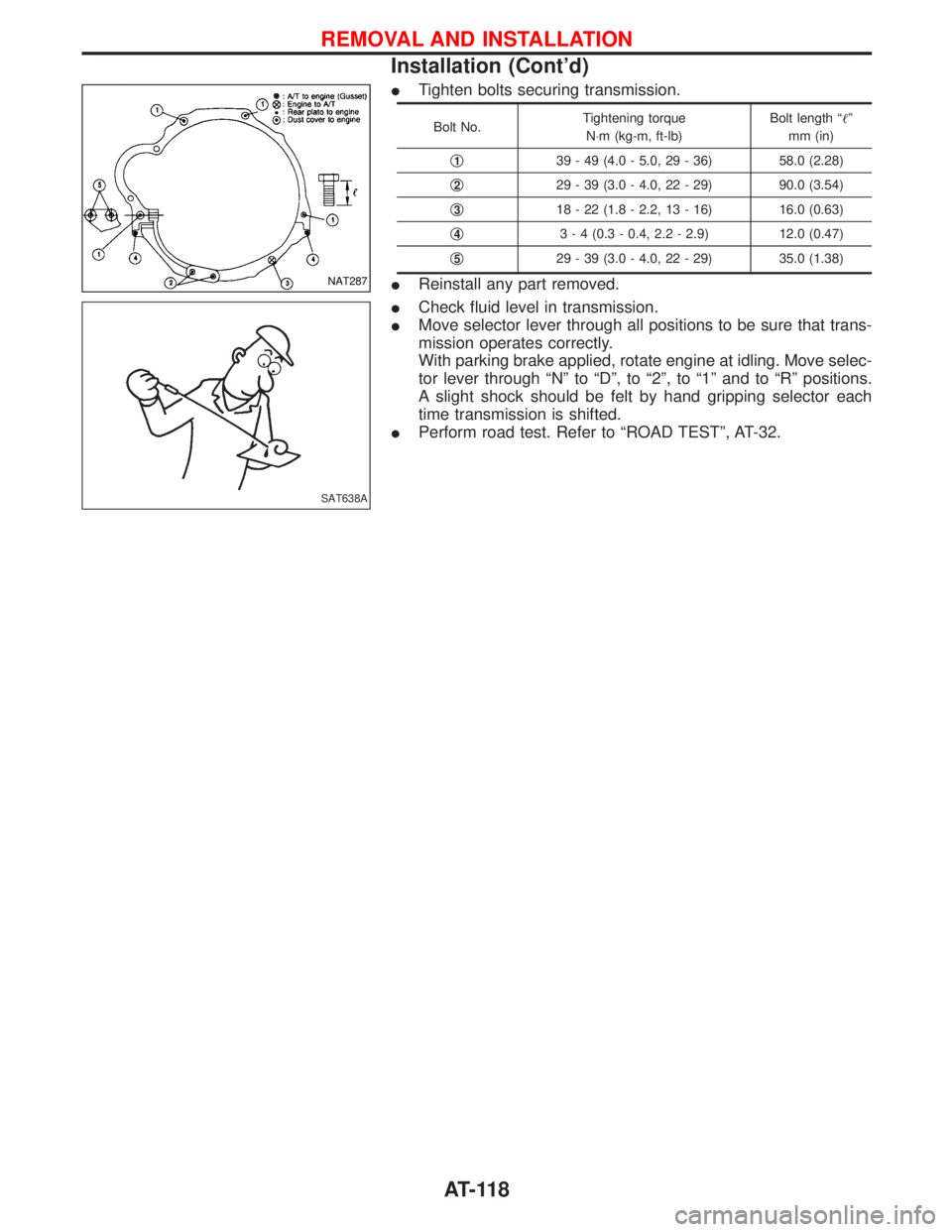
ITighten bolts securing transmission.
Bolt No.Tightening torque
N×m (kg-m, ft-lb)Bolt length ªº
mm (in)
q
139 - 49 (4.0 - 5.0, 29 - 36) 58.0 (2.28)
q
229 - 39 (3.0 - 4.0, 22 - 29) 90.0 (3.54)
q
318 - 22 (1.8 - 2.2, 13 - 16) 16.0 (0.63)
q
43 - 4 (0.3 - 0.4, 2.2 - 2.9) 12.0 (0.47)
q
529 - 39 (3.0 - 4.0, 22 - 29) 35.0 (1.38)
IReinstall any part removed.
ICheck fluid level in transmission.
IMove selector lever through all positions to be sure that trans-
mission operates correctly.
With parking brake applied, rotate engine at idling. Move selec-
tor lever through ªNº to ªDº, to ª2º, to ª1º and to ªRº positions.
A slight shock should be felt by hand gripping selector each
time transmission is shifted.
IPerform road test. Refer to ªROAD TESTº, AT-32.NAT287
SAT638A
REMOVAL AND INSTALLATION
Installation (Cont'd)
AT-118
Page 125 of 1767
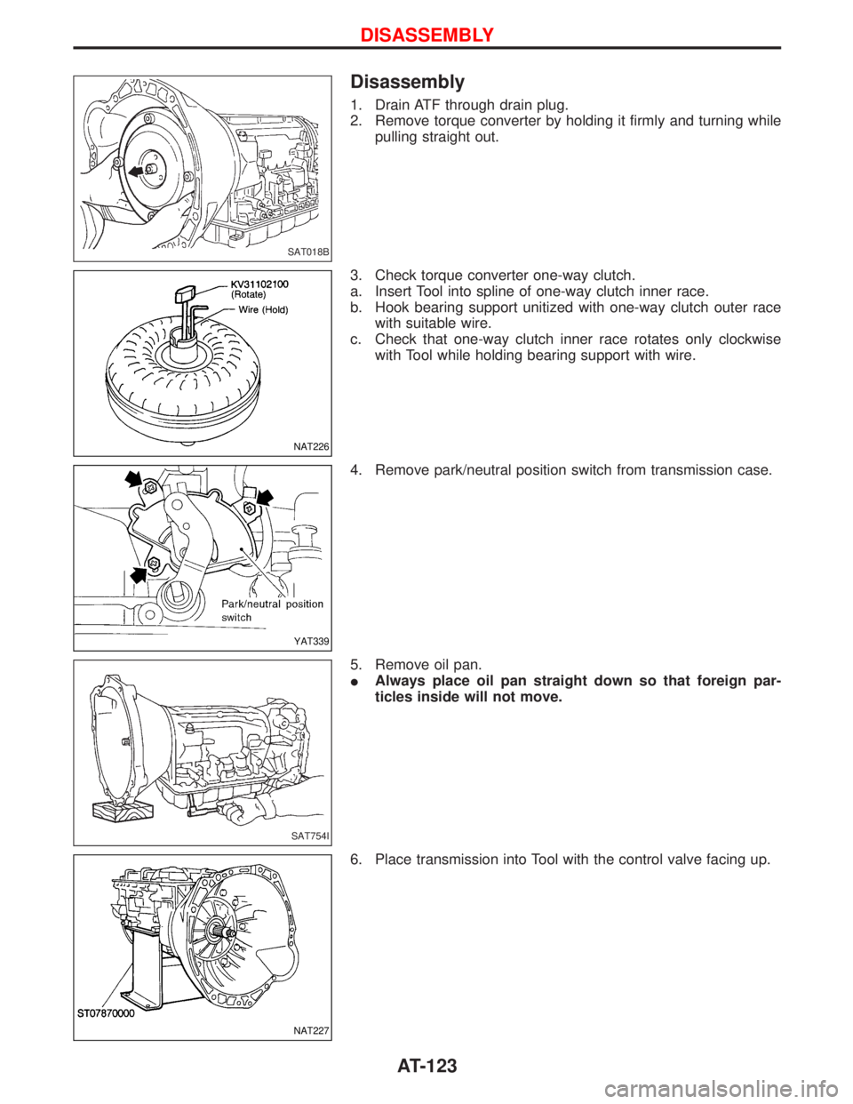
Disassembly
1. Drain ATF through drain plug.
2. Remove torque converter by holding it firmly and turning while
pulling straight out.
3. Check torque converter one-way clutch.
a. Insert Tool into spline of one-way clutch inner race.
b. Hook bearing support unitized with one-way clutch outer race
with suitable wire.
c. Check that one-way clutch inner race rotates only clockwise
with Tool while holding bearing support with wire.
4. Remove park/neutral position switch from transmission case.
5. Remove oil pan.
IAlways place oil pan straight down so that foreign par-
ticles inside will not move.
6. Place transmission into Tool with the control valve facing up.
SAT018B
NAT226
YAT339
SAT754I
NAT227
DISASSEMBLY
AT-123
Page 126 of 1767
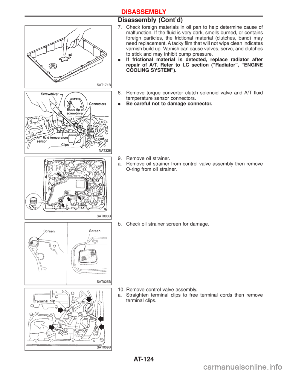
7. Check foreign materials in oil pan to help determine cause of
malfunction. If the fluid is very dark, smells burned, or contains
foreign particles, the frictional material (clutches, band) may
need replacement. A tacky film that will not wipe clean indicates
varnish build up. Varnish can cause valves, servo, and clutches
to stick and may inhibit pump pressure.
IIf frictional material is detected, replace radiator after
repair of A/T. Refer to LC section (ªRadiatorº, ªENGINE
COOLING SYSTEMº).
8. Remove torque converter clutch solenoid valve and A/T fluid
temperature sensor connectors.
IBe careful not to damage connector.
9. Remove oil strainer.
a. Remove oil strainer from control valve assembly then remove
O-ring from oil strainer.
b. Check oil strainer screen for damage.
10. Remove control valve assembly.
a. Straighten terminal clips to free terminal cords then remove
terminal clips.
SAT171B
NAT228
SAT008B
SAT025B
SAT009B
DISASSEMBLY
Disassembly (Cont'd)
AT-124
Page 141 of 1767
DISASSEMBLY
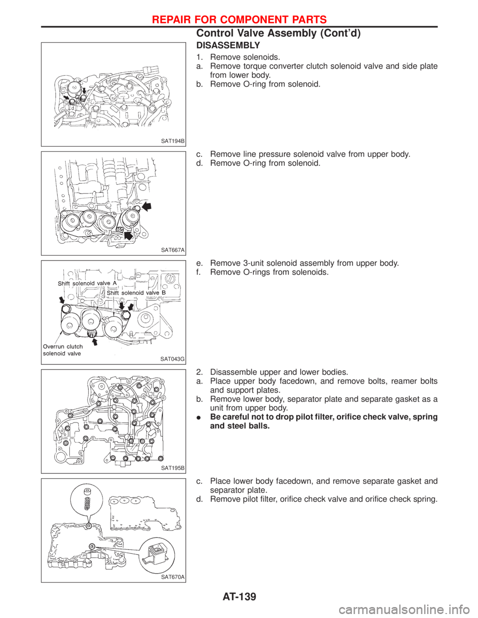
1. Remove solenoids.
a. Remove torque converter clutch solenoid valve and side plate
from lower body.
b. Remove O-ring from solenoid.
c. Remove line pressure solenoid valve from upper body.
d. Remove O-ring from solenoid.
e. Remove 3-unit solenoid assembly from upper body.
f. Remove O-rings from solenoids.
2. Disassemble upper and lower bodies.
a. Place upper body facedown, and remove bolts, reamer bolts
and support plates.
b. Remove lower body, separator plate and separate gasket as a
unit from upper body.
IBe careful not to drop pilot filter, orifice check valve, spring
and steel balls.
c. Place lower body facedown, and remove separate gasket and
separator plate.
d. Remove pilot filter, orifice check valve and orifice check spring.
SAT194B
SAT667A
SAT043G
SAT195B
SAT670A
REPAIR FOR COMPONENT PARTS
Control Valve Assembly (Cont'd)
AT-139
Page 143 of 1767
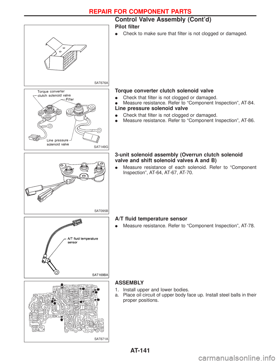
Pilot filter
ICheck to make sure that filter is not clogged or damaged.
Torque converter clutch solenoid valve
ICheck that filter is not clogged or damaged.
IMeasure resistance. Refer to ªComponent Inspectionº, AT-84.
Line pressure solenoid valve
ICheck that filter is not clogged or damaged.
IMeasure resistance. Refer to ªComponent Inspectionº, AT-86.
3-unit solenoid assembly (Overrun clutch solenoid
valve and shift solenoid valves A and B)
IMeasure resistance of each solenoid. Refer to ªComponent
Inspectionº, AT-64, AT-67, AT-70.
A/T fluid temperature sensor
IMeasure resistance. Refer to ªComponent Inspectionº, AT-78.
ASSEMBLY
1. Install upper and lower bodies.
a. Place oil circuit of upper body face up. Install steel balls in their
proper positions.
SAT676A
SAT149G
SAT095B
SAT169BA
SAT671A
REPAIR FOR COMPONENT PARTS
Control Valve Assembly (Cont'd)
AT-141