Page 609 of 1767
17 CHECK GLOW PLUG
1. Remove glow plug connecting plate.
2. Check glow plug resistance.
MEC005EResistance: Approx. 0.5W[at 20ÉC (68ÉF)]
NOTE:
IDo not bump glow plug heating element. If it is bumped, replace glow plug with a new one.
IIf glow plug is dropped from a height of 10 cm (3.94 in) or higher, replace with a new one.
IIf glow plug installation hole is contaminated with carbon, remove it with a reamer or suitable tool.
IHand-tighten glow plug by turning it two or three times, then tighten using a tool to specified torque.
:15-20N×m (1.5 - 2.1 kg-m, 11 - 15 ft-lb)
OK or NG
OKEGO TO 18.
NGEReplace glow plug.
18 CHECK INTERMITTENT INCIDENT
Refer to ªTROUBLE DIAGNOSIS FOR INTERMITTENT INCIDENTº, EC-78.
EINSPECTION END
GLOW CONTROL SYSTEMZD30DDTi
Diagnostic Procedure (Cont'd)
EC-247
Page 758 of 1767
Component Inspection
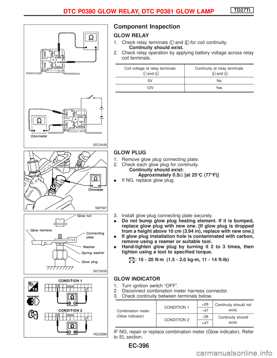
GLOW RELAY
1. Check relay terminalsq1andq2for coil continuity.
Continuity should exist.
2. Check relay operation by applying battery voltage across relay
coil terminals.
Coil voltage at relay terminals
q
1andq2
Continuity at relay terminals
q
5andq3
0V No
12V Yes
GLOW PLUG
1. Remove glow plug connecting plate.
2. Check each glow plug for continuity.
Continuity should exist:
Approximately 0.5W[at 25ÉC (77ÉF)]
IIf NG, replace glow plug.
3. Install glow plug connecting plate securely.
IDo not bump glow plug heating element. If it is bumped,
replace glow plug with new one. [If glow plug is dropped
from a height above 10 cm (3.94 in), replace with new one.]
IIf glow plug installation hole is contaminated with carbon,
remove using a reamer or suitable tool.
IHand-tighten glow plug by turning it 2 to 3 times, then
tighten using a tool to specified torque.
:15-20N×m (1.5 - 2.0 kg-m, 11 - 14 ft-lb)
GLOW INDICATOR
1. Turn ignition switch ªOFFº.
2. Disconnect combination meter harness connector.
3. Check continuity between terminals below.
Combination meter
(Glow indicator)CONDITION 1+28
Continuity should not
exist.
þ47
CONDITION 2þ28
Continuity should
exist.
+47
IF NG, repair or replace combination meter (Glow indicator). Refer
to EL section.
SEC564B
NEF507
SEC565B
YEC258A
DTC P0380 GLOW RELAY, DTC P0381 GLOW LAMPTD27Ti
EC-396
Page 914 of 1767
Installation
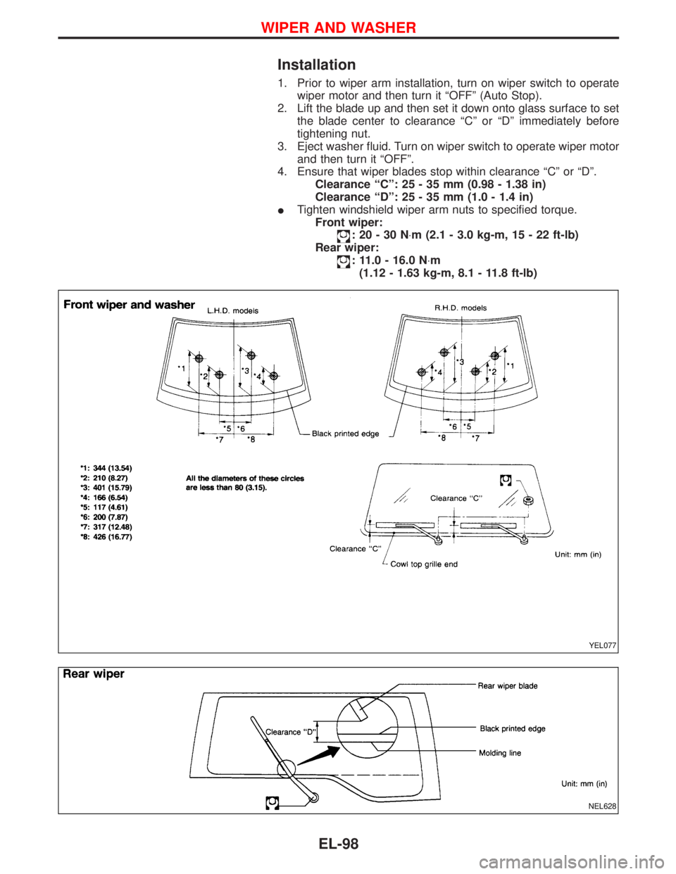
1. Prior to wiper arm installation, turn on wiper switch to operate
wiper motor and then turn it ªOFFº (Auto Stop).
2. Lift the blade up and then set it down onto glass surface to set
the blade center to clearance ªCº or ªDº immediately before
tightening nut.
3. Eject washer fluid. Turn on wiper switch to operate wiper motor
and then turn it ªOFFº.
4. Ensure that wiper blades stop within clearance ªCº or ªDº.
Clearance ªCº: 25 - 35 mm (0.98 - 1.38 in)
Clearance ªDº: 25 - 35 mm (1.0 - 1.4 in)
ITighten windshield wiper arm nuts to specified torque.
Front wiper:
:20-30N×m (2.1 - 3.0 kg-m, 15 - 22 ft-lb)
Rear wiper:
: 11.0 - 16.0 N×m
(1.12 - 1.63 kg-m, 8.1 - 11.8 ft-lb)
YEL077
NEL628
WIPER AND WASHER
EL-98
Page 1108 of 1767
Code Section Wiring Diagram Name
SROOF EL SUNROOF
SRS RSSUPPLEMENTAL RESTRAINT SYS-
TEM
SSV/A AT SHIFT SOLENOID VALVE A
SSV/B AT SHIFT SOLENOID VALVE B
START SC STARTING SYSTEM
STOP/L EL STOP LAMP
SWL/V ECSWIRL CONTROL VALVE CON-
TROL SOLENOID VALVE
TAIL/L ELPARKING, LICENSE, TAIL AND
STOP LAMPS
TCV ATTORQUE CONVERTER CLUTCH
SOLENOID VALVE
THEFT ELVEHICLE SECURITY (THEFT
WARNING) SYSTEM
THLCNT ECTHROTTLE CONTROL SOLENOID
VA LV ECode Section Wiring Diagram Name
TURN ELTURN SIGNAL AND HAZARD
WARNING LAMP
TVC&SO EC TVC AND SHUT OFF
VNT ECVARIABLE NOZZLE TURBO-
CHARGER CONTROL SOLENOID
VA LV E
VSS EC VEHICLE SPEED SENSOR
VSSA/T ATVEHICLE SPEED SENSOR A/T
(REVOLUTION SENSOR)
VSSMTR AT VEHICLE SPEED SENSOR MTR
WARN EL WARNING LAMPS
WINDOW EL POWER WINDOW
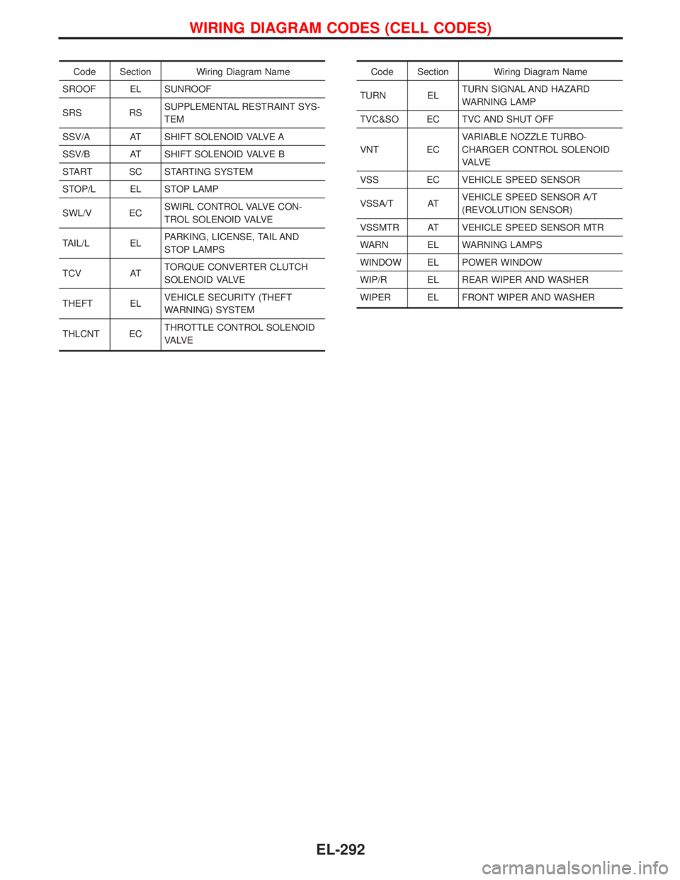
WIP/R EL REAR WIPER AND WASHER
WIPER EL FRONT WIPER AND WASHER
WIRING DIAGRAM CODES (CELL CODES)
EL-292
Page 1111 of 1767
Parts Requiring Angular Tightening
IUse an angle wrench for the final tightening of the cylinder head
bolts.
IDo not use a torque value for final tightening.
IThe torque value for these parts are for a preliminary step.
IEnsure thread and seat surfaces are clean and coated with
engine oil.
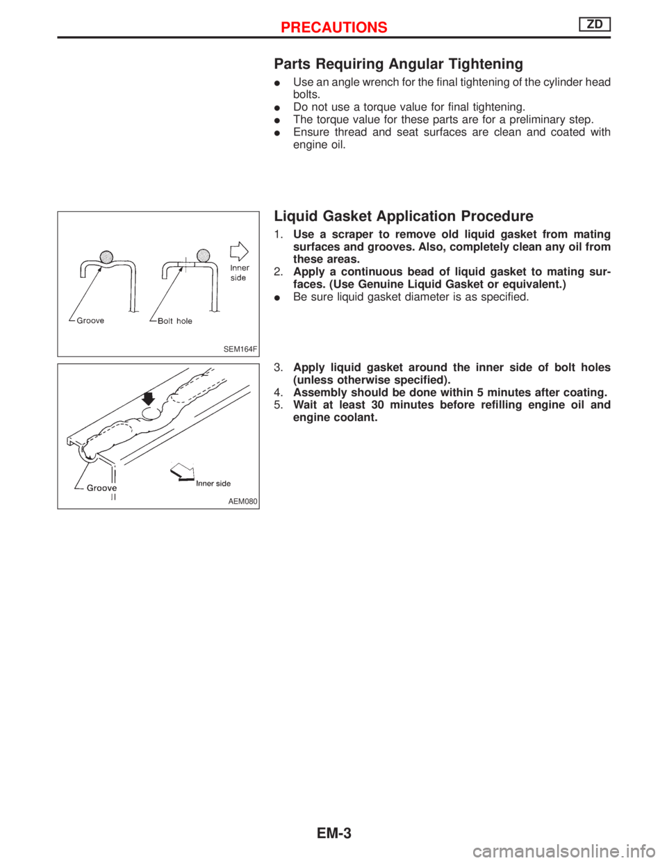
Liquid Gasket Application Procedure
1.Use a scraper to remove old liquid gasket from mating
surfaces and grooves. Also, completely clean any oil from
these areas.
2.Apply a continuous bead of liquid gasket to mating sur-
faces. (Use Genuine Liquid Gasket or equivalent.)
IBe sure liquid gasket diameter is as specified.
3.Apply liquid gasket around the inner side of bolt holes
(unless otherwise specified).
4.Assembly should be done within 5 minutes after coating.
5.Wait at least 30 minutes before refilling engine oil and
engine coolant.
SEM164F
AEM080
PRECAUTIONSZD
EM-3
Page 1129 of 1767
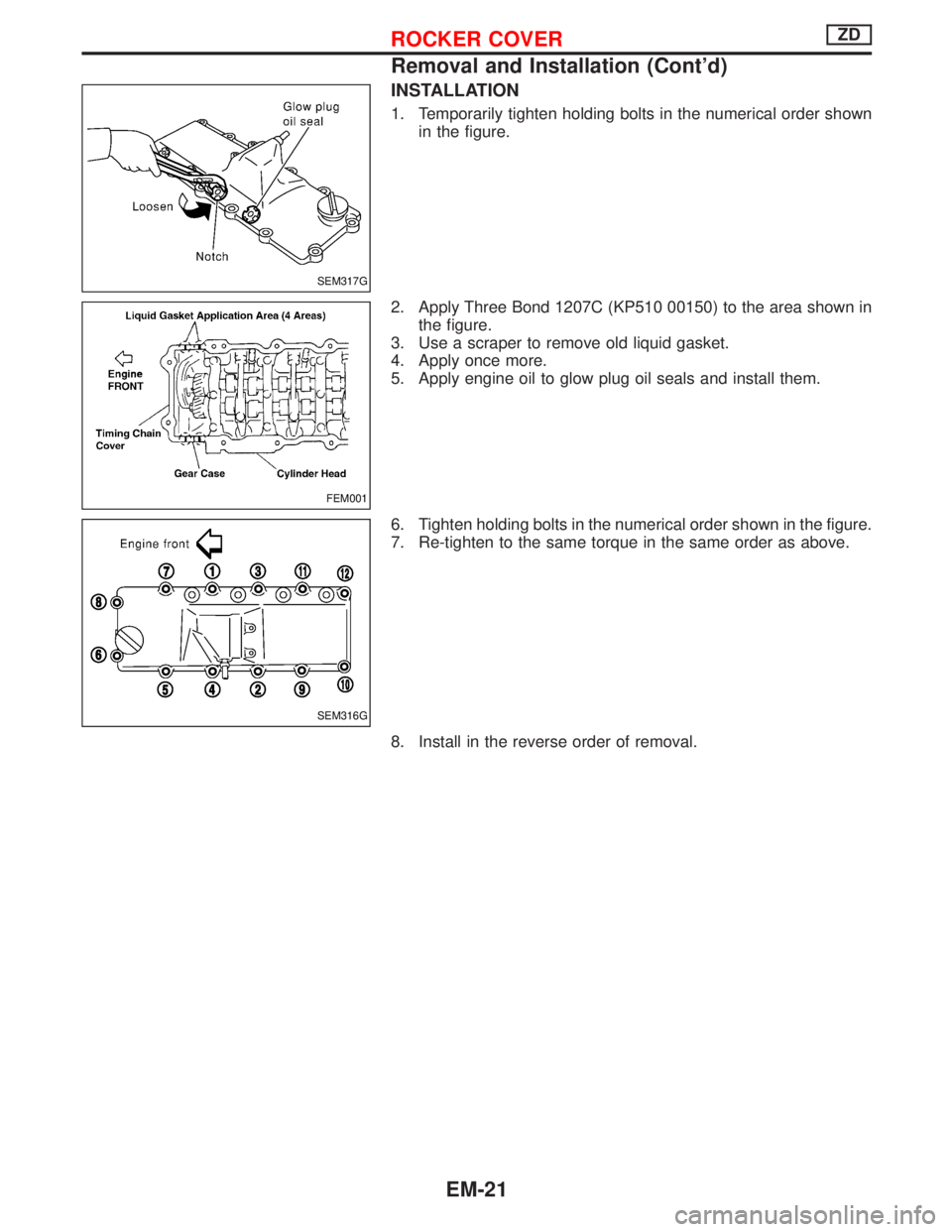
INSTALLATION
1. Temporarily tighten holding bolts in the numerical order shown
in the figure.
2. Apply Three Bond 1207C (KP510 00150) to the area shown in
the figure.
3. Use a scraper to remove old liquid gasket.
4. Apply once more.
5. Apply engine oil to glow plug oil seals and install them.
6. Tighten holding bolts in the numerical order shown in the figure.
7. Re-tighten to the same torque in the same order as above.
8. Install in the reverse order of removal.
SEM317G
FEM001
SEM316G
ROCKER COVERZD
Removal and Installation (Cont'd)
EM-21
Page 1131 of 1767
INSTALLATION
1. Install oil strainer.
2. Install oil pan.
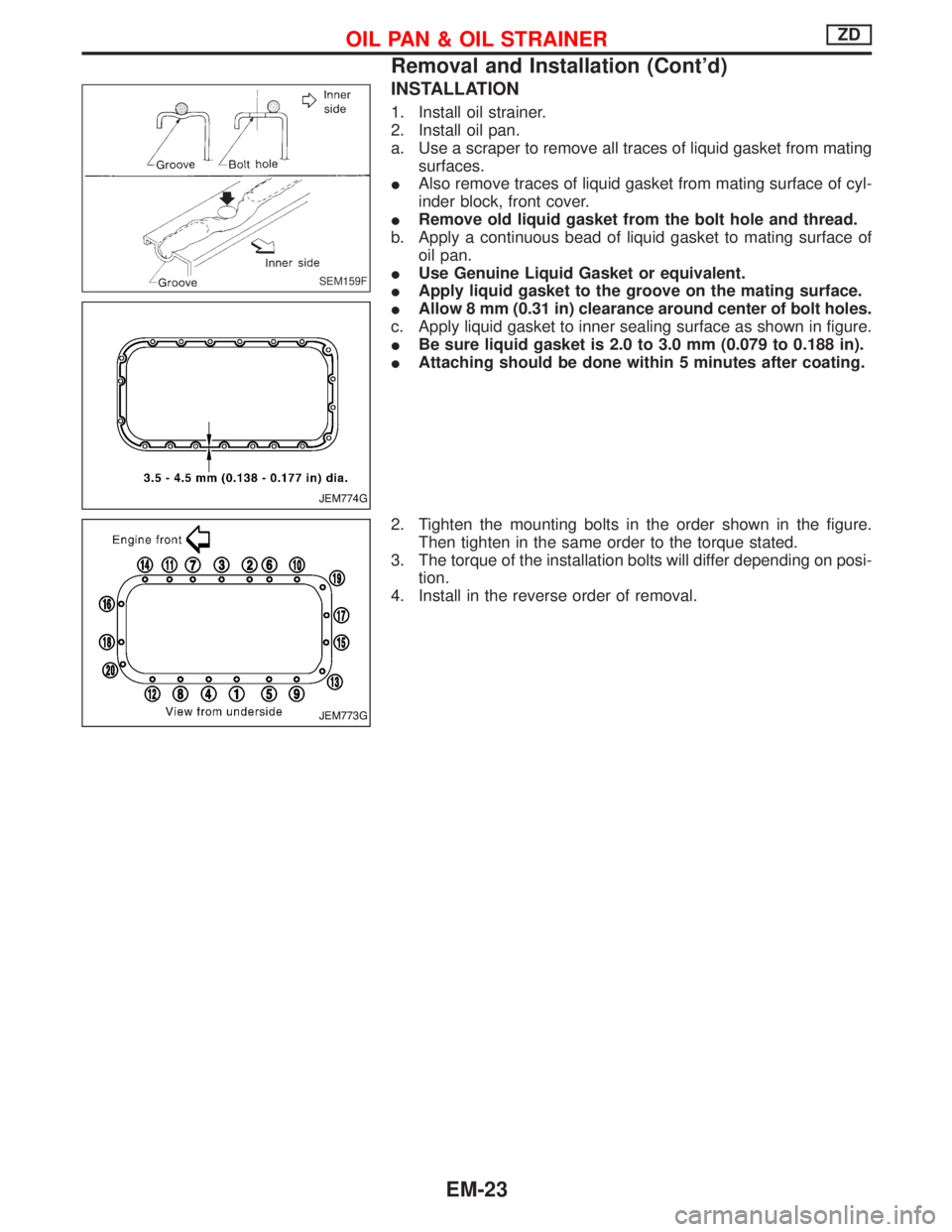
a. Use a scraper to remove all traces of liquid gasket from mating
surfaces.
IAlso remove traces of liquid gasket from mating surface of cyl-
inder block, front cover.
IRemove old liquid gasket from the bolt hole and thread.
b. Apply a continuous bead of liquid gasket to mating surface of
oil pan.
IUse Genuine Liquid Gasket or equivalent.
IApply liquid gasket to the groove on the mating surface.
IAllow 8 mm (0.31 in) clearance around center of bolt holes.
c. Apply liquid gasket to inner sealing surface as shown in figure.
IBe sure liquid gasket is 2.0 to 3.0 mm (0.079 to 0.188 in).
IAttaching should be done within 5 minutes after coating.
2. Tighten the mounting bolts in the order shown in the figure.
Then tighten in the same order to the torque stated.
3. The torque of the installation bolts will differ depending on posi-
tion.
4. Install in the reverse order of removal.
SEM159F
JEM774G
JEM773G
OIL PAN & OIL STRAINERZD
Removal and Installation (Cont'd)
EM-23
Page 1136 of 1767
6. Remove the timing chain slack guide.
7. Remove the timing chain with cam sprocket.
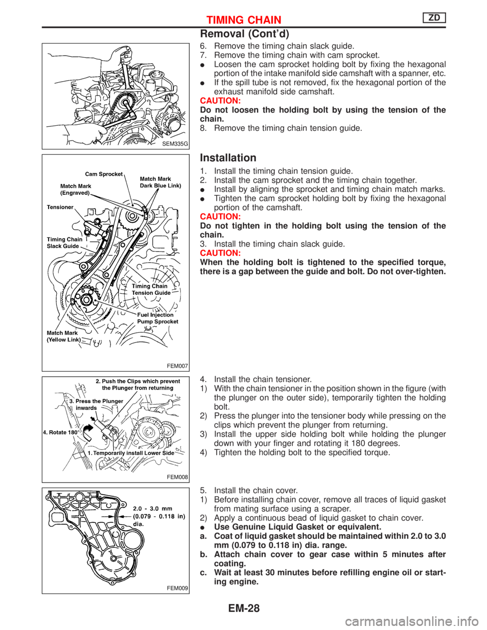
ILoosen the cam sprocket holding bolt by fixing the hexagonal
portion of the intake manifold side camshaft with a spanner, etc.
IIf the spill tube is not removed, fix the hexagonal portion of the
exhaust manifold side camshaft.
CAUTION:
Do not loosen the holding bolt by using the tension of the
chain.
8. Remove the timing chain tension guide.
Installation
1. Install the timing chain tension guide.
2. Install the cam sprocket and the timing chain together.
IInstall by aligning the sprocket and timing chain match marks.
ITighten the cam sprocket holding bolt by fixing the hexagonal
portion of the camshaft.
CAUTION:
Do not tighten in the holding bolt using the tension of the
chain.
3. Install the timing chain slack guide.
CAUTION:
When the holding bolt is tightened to the specified torque,
there is a gap between the guide and bolt. Do not over-tighten.
4. Install the chain tensioner.
1) With the chain tensioner in the position shown in the figure (with
the plunger on the outer side), temporarily tighten the holding
bolt.
2) Press the plunger into the tensioner body while pressing on the
clips which prevent the plunger from returning.
3) Install the upper side holding bolt while holding the plunger
down with your finger and rotating it 180 degrees.
4) Tighten the holding bolt to the specified torque.
5. Install the chain cover.
1) Before installing chain cover, remove all traces of liquid gasket
from mating surface using a scraper.
2) Apply a continuous bead of liquid gasket to chain cover.
IUse Genuine Liquid Gasket or equivalent.
a. Coat of liquid gasket should be maintained within 2.0 to 3.0
mm (0.079 to 0.118 in) dia. range.
b. Attach chain cover to gear case within 5 minutes after
coating.
c. Wait at least 30 minutes before refilling engine oil or start-
ing engine.
SEM335G
FEM007
FEM008
FEM009
TIMING CHAINZD
Removal (Cont'd)
EM-28
![NISSAN TERRANO 2002 Service Repair Manual 17 CHECK GLOW PLUG
1. Remove glow plug connecting plate.
2. Check glow plug resistance.
MEC005EResistance: Approx. 0.5W[at 20ÉC (68ÉF)]
NOTE:
IDo not bump glow plug heating element. If it is bumped,](/manual-img/5/57393/w960_57393-608.png "NISSAN TERRANO 2002 Service Repair Manual 17 CHECK GLOW PLUG
1. Remove glow plug connecting plate.
2. Check glow plug resistance.
MEC005EResistance: Approx. 0.5W[at 20ÉC (68ÉF)]
NOTE:
IDo not bump glow plug heating element. If it is bumped,")