Page 1186 of 1767
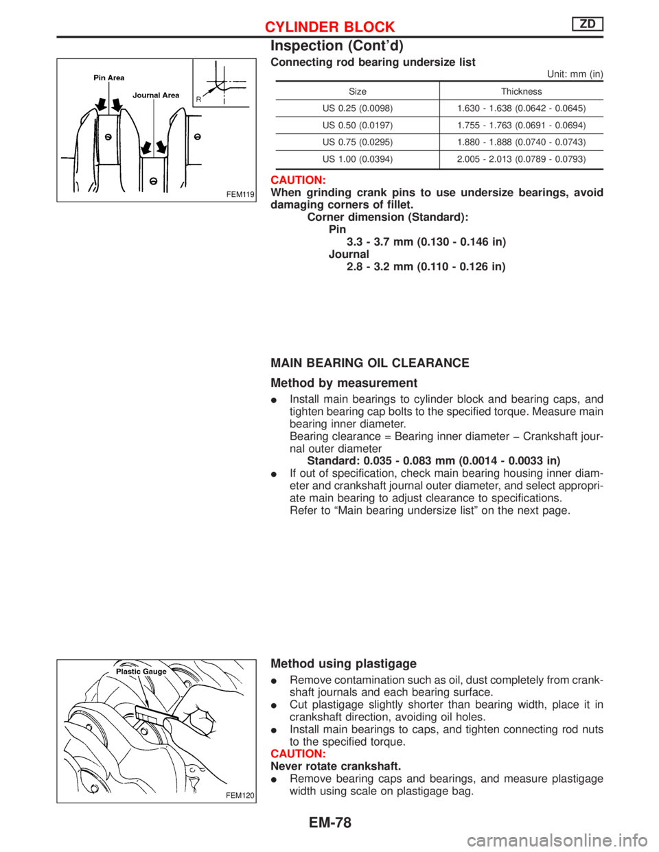
Connecting rod bearing undersize list
Unit: mm (in)
Size Thickness
US 0.25 (0.0098) 1.630 - 1.638 (0.0642 - 0.0645)
US 0.50 (0.0197) 1.755 - 1.763 (0.0691 - 0.0694)
US 0.75 (0.0295) 1.880 - 1.888 (0.0740 - 0.0743)
US 1.00 (0.0394) 2.005 - 2.013 (0.0789 - 0.0793)
CAUTION:
When grinding crank pins to use undersize bearings, avoid
damaging corners of fillet.
Corner dimension (Standard):
Pin
3.3 - 3.7 mm (0.130 - 0.146 in)
Journal
2.8 - 3.2 mm (0.110 - 0.126 in)
MAIN BEARING OIL CLEARANCE
Method by measurement
IInstall main bearings to cylinder block and bearing caps, and
tighten bearing cap bolts to the specified torque. Measure main
bearing inner diameter.
Bearing clearance = Bearing inner diameter þ Crankshaft jour-
nal outer diameter
Standard: 0.035 - 0.083 mm (0.0014 - 0.0033 in)
IIf out of specification, check main bearing housing inner diam-
eter and crankshaft journal outer diameter, and select appropri-
ate main bearing to adjust clearance to specifications.
Refer to ªMain bearing undersize listº on the next page.
Method using plastigage
IRemove contamination such as oil, dust completely from crank-
shaft journals and each bearing surface.
ICut plastigage slightly shorter than bearing width, place it in
crankshaft direction, avoiding oil holes.
IInstall main bearings to caps, and tighten connecting rod nuts
to the specified torque.
CAUTION:
Never rotate crankshaft.
IRemove bearing caps and bearings, and measure plastigage
width using scale on plastigage bag.
FEM119
FEM120
CYLINDER BLOCKZD
Inspection (Cont'd)
EM-78
Page 1187 of 1767
CAUTION:
If out of specification, take same action mentioned in ªMethod
by measurementº.
Undersize bearing usage
IIf bearing clearance is out of specifications for main bearings
in standard size, use undersize bearings.
IWhen using undersize bearings, measure bearing inner diam-
eter with bearing installed, and grind crank journals to adjust
clearance to specification.
Main bearing undersize list
Unit: mm (in)
Size Thickness
US 0.25 (0.0098) 2.130 - 2.138 (0.0839 - 0.0842)
US 0.50 (0.0197) 2.255 - 2.263 (0.0888 - 0.0891)
US 0.75 (0.0295) 2.380 - 2.388 (0.0937 - 0.0940)
US 1.00 (0.0394) 2.505 - 2.513 (0.0986 - 0.0989)
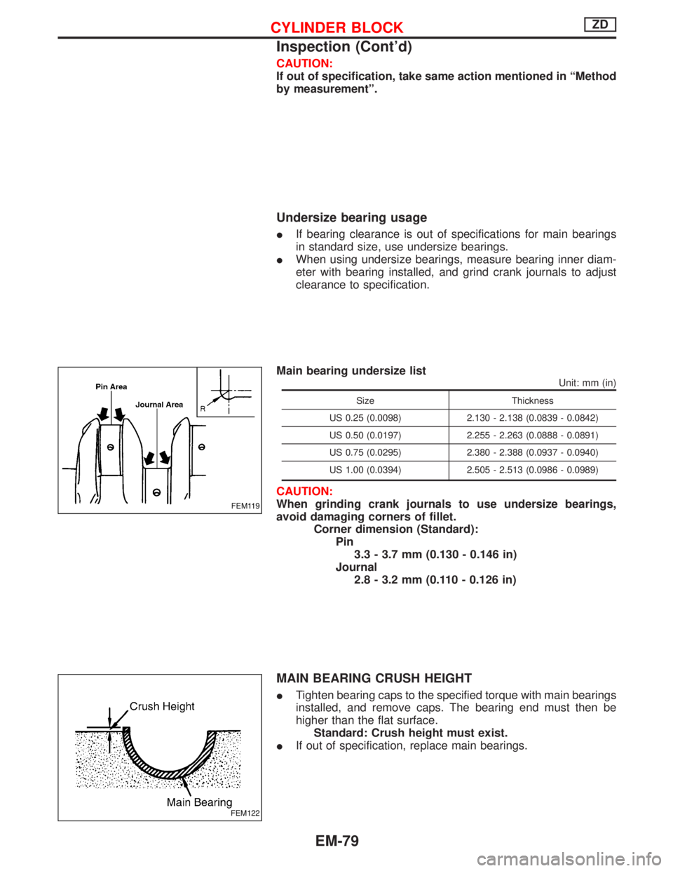
CAUTION:
When grinding crank journals to use undersize bearings,
avoid damaging corners of fillet.
Corner dimension (Standard):
Pin
3.3 - 3.7 mm (0.130 - 0.146 in)
Journal
2.8 - 3.2 mm (0.110 - 0.126 in)
MAIN BEARING CRUSH HEIGHT
ITighten bearing caps to the specified torque with main bearings
installed, and remove caps. The bearing end must then be
higher than the flat surface.
Standard: Crush height must exist.
IIf out of specification, replace main bearings.
FEM119
FEM122
CYLINDER BLOCKZD
Inspection (Cont'd)
EM-79
Page 1188 of 1767
Assembly
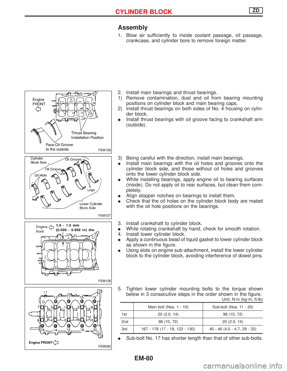
1. Blow air sufficiently to inside coolant passage, oil passage,
crankcase, and cylinder bore to remove foreign matter.
2. Install main bearings and thrust bearings.
1) Remove contamination, dust and oil from bearing mounting
positions on cylinder block and main bearing caps.
2) Install thrust bearings on both sides of No. 4 housing on cylin-
der block.
IInstall thrust bearings with oil groove facing to crankshaft arm
(outside).
3) Being careful with the direction, install main bearings.
IInstall main bearings with the oil holes and grooves onto the
cylinder block side, and those without oil holes and grooves
onto the lower cylinder block side.
IWhile installing bearings, apply engine oil to bearing surfaces
(inside). Do not apply oil to rear surfaces, but clean them com-
pletely.
IAlign stopper notches on bearings to install them.
ICheck that the oil holes on the cylinder block body are mated
with the oil hole positions on the bearings.
3. Install crankshaft to cylinder block.
IWhile rotating crankshaft by hand, check for smooth rotation.
4. Install lower cylinder block.
IApply a continuous bead of liquid gasket to lower cylinder block
as shown in the figure.
IUsing slots on engine sub-attachment, install the lower cylinder
block to the cylinder block, avoiding interference of dowel pins.
5. Tighten lower cylinder mounting bolts to the torque shown
below in 3 consecutive steps in the order shown in the figure.
Unit: N×m (kg-m, ft-lb)
Main bolt (Nos. 1 - 10) Sub-bolt (Nos. 11 - 20)
1st 20 (2.0, 14) 98 (10, 72)
2nd 98 (10, 72) 20 (2.0, 14)
3rd 167 - 176 (17 - 18, 123 - 130) 40 - 46 (4.0 - 4.7, 29 - 33)
ISub-bolt No. 17 has shorter length than that of other sub-bolts.
FEM126
FEM127
FEM128
FEM092
CYLINDER BLOCKZD
EM-80
Page 1189 of 1767
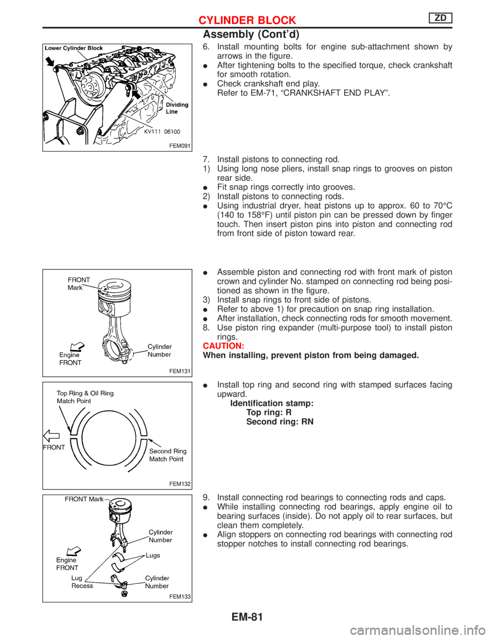
6. Install mounting bolts for engine sub-attachment shown by
arrows in the figure.
IAfter tightening bolts to the specified torque, check crankshaft
for smooth rotation.
ICheck crankshaft end play.
Refer to EM-71, ªCRANKSHAFT END PLAYº.
7. Install pistons to connecting rod.
1) Using long nose pliers, install snap rings to grooves on piston
rear side.
IFit snap rings correctly into grooves.
2) Install pistons to connecting rods.
IUsing industrial dryer, heat pistons up to approx. 60 to 70ÉC
(140 to 158ÉF) until piston pin can be pressed down by finger
touch. Then insert piston pins into piston and connecting rod
from front side of piston toward rear.
IAssemble piston and connecting rod with front mark of piston
crown and cylinder No. stamped on connecting rod being posi-
tioned as shown in the figure.
3) Install snap rings to front side of pistons.
IRefer to above 1) for precaution on snap ring installation.
IAfter installation, check connecting rods for smooth movement.
8. Use piston ring expander (multi-purpose tool) to install piston
rings.
CAUTION:
When installing, prevent piston from being damaged.
IInstall top ring and second ring with stamped surfaces facing
upward.
Identification stamp:
Top ring: R
Second ring: RN
9. Install connecting rod bearings to connecting rods and caps.
IWhile installing connecting rod bearings, apply engine oil to
bearing surfaces (inside). Do not apply oil to rear surfaces, but
clean them completely.
IAlign stoppers on connecting rod bearings with connecting rod
stopper notches to install connecting rod bearings.
FEM091
FEM131
FEM132
FEM133
CYLINDER BLOCKZD
Assembly (Cont'd)
EM-81
Page 1203 of 1767
Parts Requiring Angular Tightening
ISome important engine parts are tightened using an angular-
tightening method rather than a torque setting method.
IIf these parts are tightened using a torque setting method, dis-
persal of the tightening force (axial bolt force) will be two or
three times that of the dispersal produced by using the correct
angular-tightening method.
IAlthough the torque setting values (described in this manual)
are equivalent to those used when bolts and nuts are tightened
with an angular-tightening method, they should be used for
reference only.
ITo assure the satisfactory maintenance of the engine, bolts and
nuts must be tightened using an angular-tightening method.
IBefore tightening the bolts and nuts, ensure that the thread and
seating surfaces are clean and then coated with engine oil.
IThe bolts and nuts which require the angular-tightening method
are as follows:
(1) Cylinder head bolts
(2) Connecting rod cap nuts
Liquid Gasket Application Procedure
a. Before applying liquid gasket, use a scraper to remove all
traces of old liquid gasket from mating surface and
grooves, and then completely clean any oil stains from
these portions.
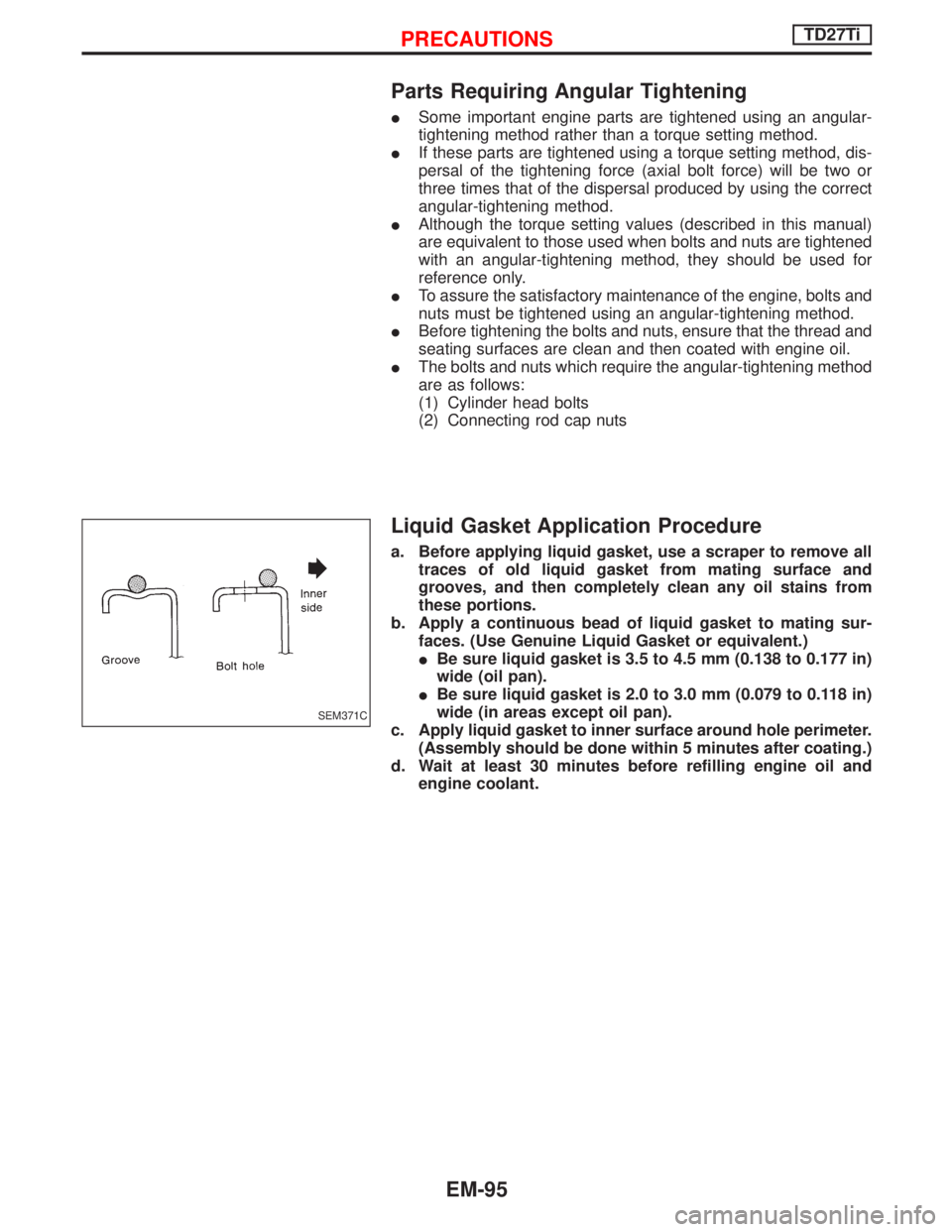
b. Apply a continuous bead of liquid gasket to mating sur-
faces. (Use Genuine Liquid Gasket or equivalent.)
IBe sure liquid gasket is 3.5 to 4.5 mm (0.138 to 0.177 in)
wide (oil pan).
IBe sure liquid gasket is 2.0 to 3.0 mm (0.079 to 0.118 in)
wide (in areas except oil pan).
c. Apply liquid gasket to inner surface around hole perimeter.
(Assembly should be done within 5 minutes after coating.)
d. Wait at least 30 minutes before refilling engine oil and
engine coolant.
SEM371C
PRECAUTIONSTD27Ti
EM-95
Page 1261 of 1767
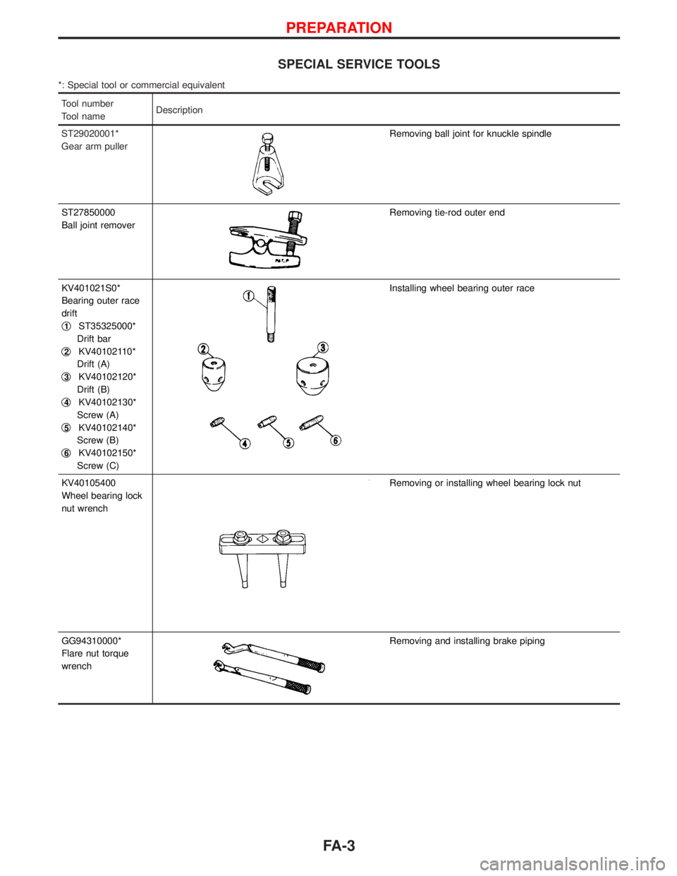
SPECIAL SERVICE TOOLS
*: Special tool or commercial equivalent
Tool number
Tool nameDescription
ST29020001*
Gear arm puller
Removing ball joint for knuckle spindle
ST27850000
Ball joint remover
Removing tie-rod outer end
KV401021S0*
Bearing outer race
drift
q
1ST35325000*
Drift bar
q
2KV40102110*
Drift (A)
q
3KV40102120*
Drift (B)
q
4KV40102130*
Screw (A)
q
5KV40102140*
Screw (B)
q
6KV40102150*
Screw (C)
Installing wheel bearing outer race
KV40105400
Wheel bearing lock
nut wrench
Removing or installing wheel bearing lock nut
GG94310000*
Flare nut torque
wrench
Removing and installing brake piping
PREPARATION
FA-3
Page 1263 of 1767
Front Axle and Front Suspension Parts
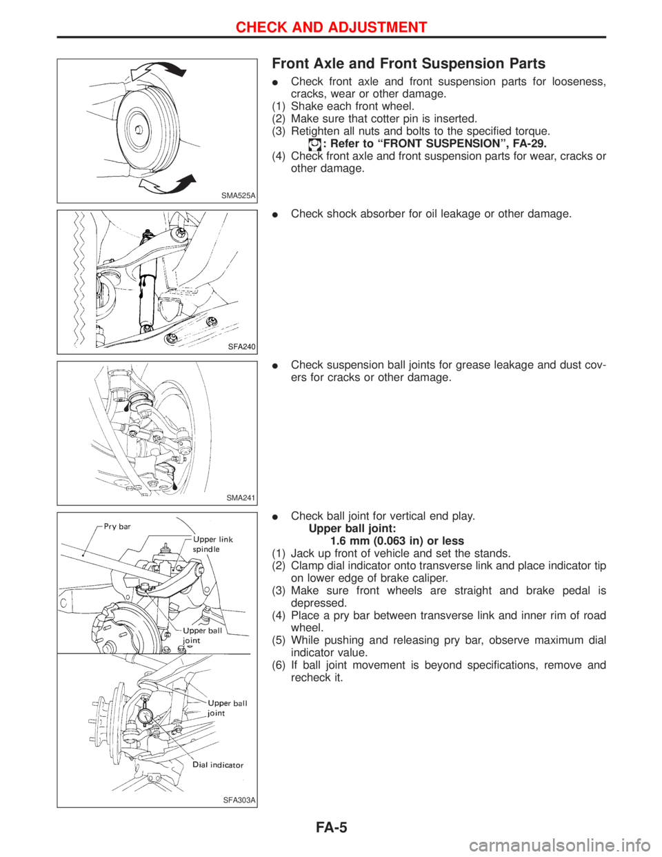
ICheck front axle and front suspension parts for looseness,
cracks, wear or other damage.
(1) Shake each front wheel.
(2) Make sure that cotter pin is inserted.
(3) Retighten all nuts and bolts to the specified torque.
: Refer to ªFRONT SUSPENSIONº, FA-29.
(4) Check front axle and front suspension parts for wear, cracks or
other damage.
ICheck shock absorber for oil leakage or other damage.
ICheck suspension ball joints for grease leakage and dust cov-
ers for cracks or other damage.
ICheck ball joint for vertical end play.
Upper ball joint:
1.6 mm (0.063 in) or less
(1) Jack up front of vehicle and set the stands.
(2) Clamp dial indicator onto transverse link and place indicator tip
on lower edge of brake caliper.
(3) Make sure front wheels are straight and brake pedal is
depressed.
(4) Place a pry bar between transverse link and inner rim of road
wheel.
(5) While pushing and releasing pry bar, observe maximum dial
indicator value.
(6) If ball joint movement is beyond specifications, remove and
recheck it.
SMA525A
SFA240
SMA241
SFA303A
CHECK AND ADJUSTMENT
FA-5
Page 1265 of 1767
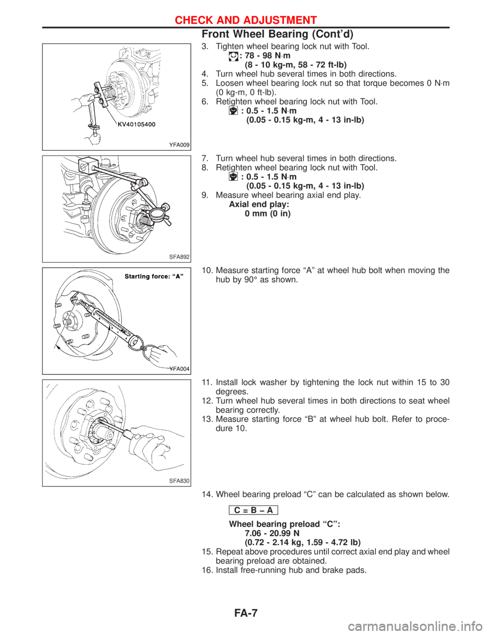
3. Tighten wheel bearing lock nut with Tool.
:78-98N×m
(8 - 10 kg-m, 58 - 72 ft-lb)
4. Turn wheel hub several times in both directions.
5. Loosen wheel bearing lock nut so that torque becomes 0 N×m
(0 kg-m, 0 ft-lb).
6. Retighten wheel bearing lock nut with Tool.
: 0.5 - 1.5 N×m
(0.05 - 0.15 kg-m,4-13in-lb)
7. Turn wheel hub several times in both directions.
8. Retighten wheel bearing lock nut with Tool.
: 0.5 - 1.5 N×m
(0.05 - 0.15 kg-m,4-13in-lb)
9. Measure wheel bearing axial end play.
Axial end play:
0mm(0in)
10. Measure starting force ªAº at wheel hub bolt when moving the
hub by 90É as shown.
11. Install lock washer by tightening the lock nut within 15 to 30
degrees.
12. Turn wheel hub several times in both directions to seat wheel
bearing correctly.
13. Measure starting force ªBº at wheel hub bolt. Refer to proce-
dure 10.
14. Wheel bearing preload ªCº can be calculated as shown below.
C=BþA
Wheel bearing preload ªCº:
7.06 - 20.99 N
(0.72 - 2.14 kg, 1.59 - 4.72 lb)
15. Repeat above procedures until correct axial end play and wheel
bearing preload are obtained.
16. Install free-running hub and brake pads.
YFA009
SFA892
YFA004
SFA830
CHECK AND ADJUSTMENT
Front Wheel Bearing (Cont'd)
FA-7