2002 NISSAN TERRANO torque
[x] Cancel search: torquePage 200 of 1767
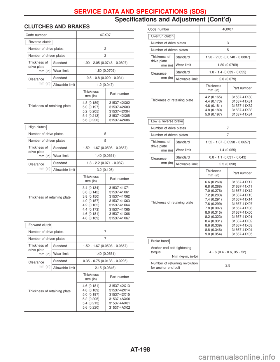
CLUTCHES AND BRAKES
Code number 4GX07
Reverse clutch
Number of drive plates 2
Number of driven plates 2
Thickness of
drive plate
mm (in)Standard 1.90 - 2.05 (0.0748 - 0.0807)
Wear limit 1.80 (0.0709)
Clearance
mm (in)Standard 0.5 - 0.8 (0.020 - 0.031)
Allowable limit 1.2 (0.047)
Thickness of retaining plateThickness
mm (in)Part number
4.8 (0.189)
5.0 (0.197)
5.2 (0.205)
5.4 (0.213)
5.6 (0.220)31537-42X02
31537-42X03
31537-42X04
31537-42X05
31537-42X06
High clutch
Number of drive plates 5
Number of driven plates 5
Thickness of
drive plate
mm (in)Standard 1.52 - 1.67 (0.0598 - 0.0657)
Wear limit 1.40 (0.0551)
Clearance
mm (in)Standard 1.8 - 2.2 (0.071 - 0.087)
Allowable limit 3.2 (0.126)
Thickness of retaining plateThickness
mm (in)Part number
3.4 (0.134)
3.6 (0.142)
3.8 (0.150)
4.0 (0.157)
4.2 (0.165)
4.4 (0.173)
4.6 (0.181)
4.8 (0.189)31537-41X71
31537-41X61
31537-41X62
31537-41X63
31537-41X64
31537-41X65
31537-41X66
31537-41X67
Forward clutch
Number of drive plates 7
Number of driven plates 7
Thickness of
drive plate
mm (in)Standard 1.52 - 1.67 (0.0598 - 0.0657)
Wear limit 1.40 (0.0551)
Clearance
mm (in)Standard 0.35 - 0.75 (0.0138 - 0.0295)
Allowable limit 2.15 (0.0846)
Thickness of retaining plateThickness
mm (in)Part number
4.6 (0.181)
4.8 (0.189)
5.0 (0.197)
5.2 (0.205)
5.4 (0.213)
5.6 (0.220)31537-42X13
31537-42X14
31537-42X15
31537-4AX00
31537-4AX01
31537-4AX02
Code number 4GX07
Overrun clutch
Number of drive plates 3
Number of driven plates 5
Thickness of
drive plate
mm (in)Standard 1.90 - 2.05 (0.0748 - 0.0807)
Wear limit 1.80 (0.0709)
Clearance
mm (in)Standard 1.0 - 1.4 (0.039 - 0.055)
Allowable limit 2.0 (0.079)
Thickness of retaining plateThickness
mm (in)Part number
4.2 (0.165)
4.4 (0.173)
4.6 (0.181)
4.8 (0.189)
5.0 (0.197)31537-41X80
31537-41X81
31537-41X82
31537-41X83
31537-41X84
Low & reverse brake
Number of drive plates 7
Number of driven plates 7
Thickness of
drive plate
mm (in)Standard 1.52 - 1.67 (0.0598 - 0.0657)
Wear limit 1.4 (0.055)
Clearance
mm (in)Standard 0.8 - 1.1 (0.031 - 0.043)
Allowable limit 2.5 (0.098)
Thickness of retaining plateThickness
mm (in)Part number
6.6 (0.260)
6.8 (0.268)
7.0 (0.276)
7.2 (0.283)
7.4 (0.291)
7.6 (0.299)
7.8 (0.307)
8.0 (0.315)
8.2 (0.323)
8.4 (0.331)
8.6 (0.339)
8.8 (0.346)
9.0 (0.354)31667-41X17
31667-41X11
31667-41X12
31667-41X13
31667-41X14
31667-41X07
31667-41X08
31667-41X00
31667-41X01
31667-41X02
31667-41X03
31667-41X04
31667-41X05
Brake band
Anchor end bolt tightening
torque
N×m (kg-m, in-lb)4 - 6 (0.4 - 0.6, 35 - 52)
Number of returning revolution
for anchor end bolt2.5
SERVICE DATA AND SPECIFICATIONS (SDS)
Specifications and Adjustment (Cont'd)
AT-198
Page 201 of 1767
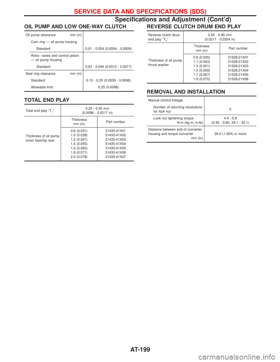
OIL PUMP AND LOW ONE-WAY CLUTCH
Oil pump clearance mm (in)
Cam ring Ð oil pump housing
Standard 0.01 - 0.024 (0.0004 - 0.0009)
Rotor, vanes and control piston
Ð oil pump housing
Standard 0.03 - 0.044 (0.0012 - 0.0017)
Seal ring clearance mm (in)
Standard 0.10 - 0.25 (0.0039 - 0.0098)
Allowable limit 0.25 (0.0098)
TOTAL END PLAY
Total end play ªT1º0.25 - 0.55 mm
(0.0098 - 0.0217 in)
Thickness of oil pump
cover bearing raceThickness
mm (in)Part number
0.8 (0.031)
1.0 (0.039)
1.2 (0.047)
1.4 (0.055)
1.6 (0.063)
1.8 (0.071)
2.0 (0.079)31435-41X01
31435-41X02
31435-41X03
31435-41X04
31435-41X05
31435-41X06
31435-41X07
REVERSE CLUTCH DRUM END PLAY
Reverse clutch drum
end play ªT
2º0.55 - 0.90 mm
(0.0217 - 0.0354 in)
Thickness of oil pump
thrust washerThickness
mm (in)Part number
0.9 (0.035)
1.1 (0.043)
1.3 (0.051)
1.5 (0.059)
1.7 (0.067)
1.9 (0.075)31528-21X01
31528-21X02
31528-21X03
31528-21X04
31528-21X05
31528-21X06
REMOVAL AND INSTALLATION
Manual control linkage
Number of returning revolutions
for lock nut2
Lock nut tightening torque
N×m (kg-m, in-lb)4.4 - 5.9
(0.45 - 0.60, 39.1 - 52.1)
Distance between end of converter
housing and torque converter
mm (in)26.0 (1.024) or more
SERVICE DATA AND SPECIFICATIONS (SDS)
Specifications and Adjustment (Cont'd)
AT-199
Page 205 of 1767
Supplement Restraint System (SRS) ªAIR BAGº
and ªSEAT BELT PRE-TENSIONERº
The Supplemental Restraint System ªAir Bagº and ªSeat Belt Pre-tensionerº, used along with a seat belt, help
to reduce the risk or severity or injury to the driver and front passenger in a collision. The Supplemental
Restraint System consists of an air bag module (located in the center of the steering wheel and on the instru-
ment panel on the passenger side, where fitted), seat belt pre-tensioners, a diagnosis sensor unit, warning
lamp, wiring harness and spiral cable. Information necessary to service the system safely is included in the
BT sectionof this Service Manual.
WARNING:
ITo avoid rendering the SRS inoperative (which could increase the risk of personal injury or death
in the event of a collision which would result in air bag inflation), all maintenance must be per-
formed by an authorized NISSAN dealer.
IImproper maintenance, including incorrect removal and installation of the SRS, can lead to per-
sonal injury caused by unintentional activation of the system.
IDo not use electrical test equipment on any circuit related to the SRS unless instructed to in this
Service Manual. SRS wiring harnesses (except ªSEAT BELT-TENSIONERº connector) can be iden-
tified with yellow harness connector and with yellow harness protector or yellow insulation tape
before the harness connectors.
Precautions
IUse only ªDOT 4º fluid from a sealed container.
INever reuse drained brake fluid.
IBe careful not to splash brake fluid on painted areas; it
may cause paint damage. If brake fluid is splashed on
painted areas, wash it away with water immediately.
ITo clean master cylinder parts, disc brake caliper parts or
wheel cylinder parts, use clean brake fluid.
INever use mineral oils such as Petrol or kerosene. They
will ruin rubber parts of hydraulic system.
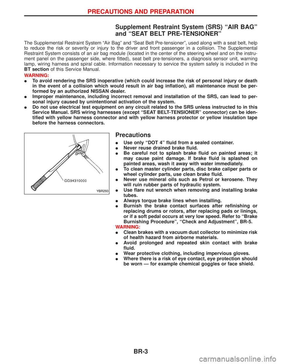
IUse flare nut wrench when removing and installing brake
tubes.
IAlways torque brake lines when installing.
IBurnish the brake contact surfaces after refinishing or
replacing drums or rotors, after replacing pads or linings,
or if a soft pedal occurs at very low speed. Refer to ªBrake
Burnishing Procedureº, ªCheck and Adjustmentº, BR-5.
WARNING:
IClean brakes with a vacuum dust collector to minimize risk
of health hazard from airborne materials.
IAvoid prolonged and repeated skin contact with brake
fluid.
IWear protective clothing, including impervious gloves.
IWhere there is a risk of eye contact, eye protection should
be worn Ð for example chemical goggles or face shield.
YBR293
PRECAUTIONS AND PREPARATION
BR-3
Page 206 of 1767
Preparation
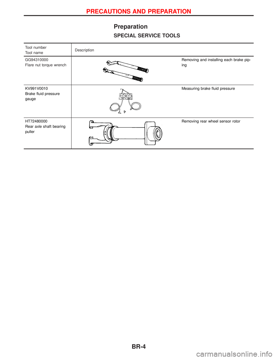
SPECIAL SERVICE TOOLS
Tool number
Tool nameDescription
GG94310000
Flare nut torque wrench
Removing and installing each brake pip-
ing
KV991V0010
Brake fluid pressure
gauge
Measuring brake fluid pressure
HT72480000
Rear axle shaft bearing
puller
Removing rear wheel sensor rotor
PRECAUTIONS AND PREPARATION
BR-4
Page 229 of 1767
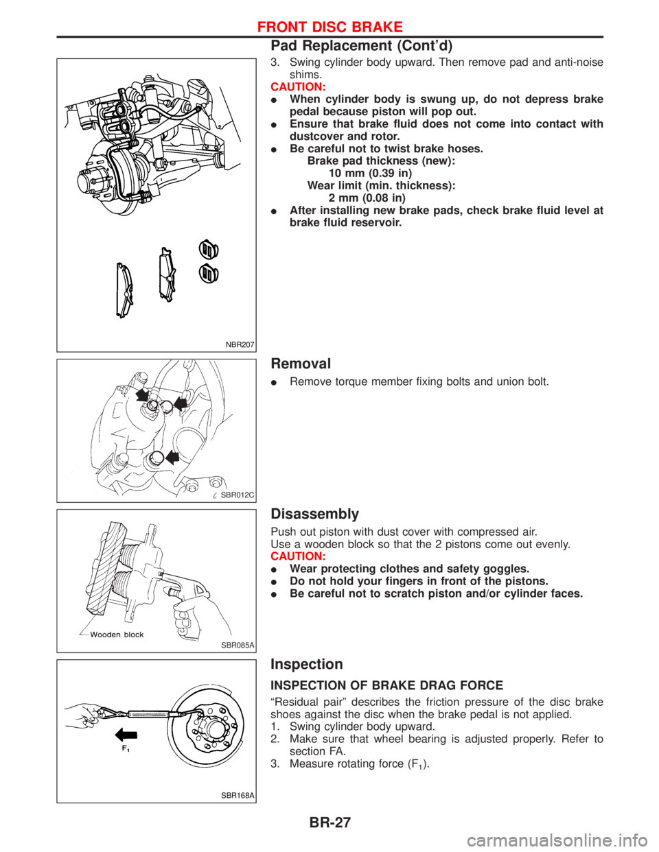
3. Swing cylinder body upward. Then remove pad and anti-noise
shims.
CAUTION:
IWhen cylinder body is swung up, do not depress brake
pedal because piston will pop out.
IEnsure that brake fluid does not come into contact with
dustcover and rotor.
IBe careful not to twist brake hoses.
Brake pad thickness (new):
10 mm (0.39 in)
Wear limit (min. thickness):
2 mm (0.08 in)
IAfter installing new brake pads, check brake fluid level at
brake fluid reservoir.
Removal
IRemove torque member fixing bolts and union bolt.
Disassembly
Push out piston with dust cover with compressed air.
Use a wooden block so that the 2 pistons come out evenly.
CAUTION:
IWear protecting clothes and safety goggles.
IDo not hold your fingers in front of the pistons.
IBe careful not to scratch piston and/or cylinder faces.
Inspection
INSPECTION OF BRAKE DRAG FORCE
ªResidual pairº describes the friction pressure of the disc brake
shoes against the disc when the brake pedal is not applied.
1. Swing cylinder body upward.
2. Make sure that wheel bearing is adjusted properly. Refer to
section FA.
3. Measure rotating force (F
1).
NBR207
SBR012C
SBR085A
SBR168A
FRONT DISC BRAKE
Pad Replacement (Cont'd)
BR-27
Page 248 of 1767
6. Loosen/remove mounting nuts between actuator and bracket.
Installation
CAUTION:
After installation, pay attention to the following points:
IRefill brake fluid and bleed air. Refer to ªCHECK AND
ADJUSTMENTº, BR-5 and ªBleeding Brake Systemº,
ªBRAKE HYDRAULIC LINEº, BR-8, respectively.
1. Install actuator on bracket without tightening fixings.
2. Assemble brake tubes to actuator without tightening tube nuts.
Ensure that correct tubes are connected to each port.
3. Fully tighten actuator and bracket fixings to specified torque.
4. Fully tighten flare nuts to specified torque, BR-9.
5. Secure ABS control unit harness connector and battery cable.
ANTI-LOCK BRAKE SYSTEM
Removal and Installation (Cont'd)
BR-46
Page 350 of 1767
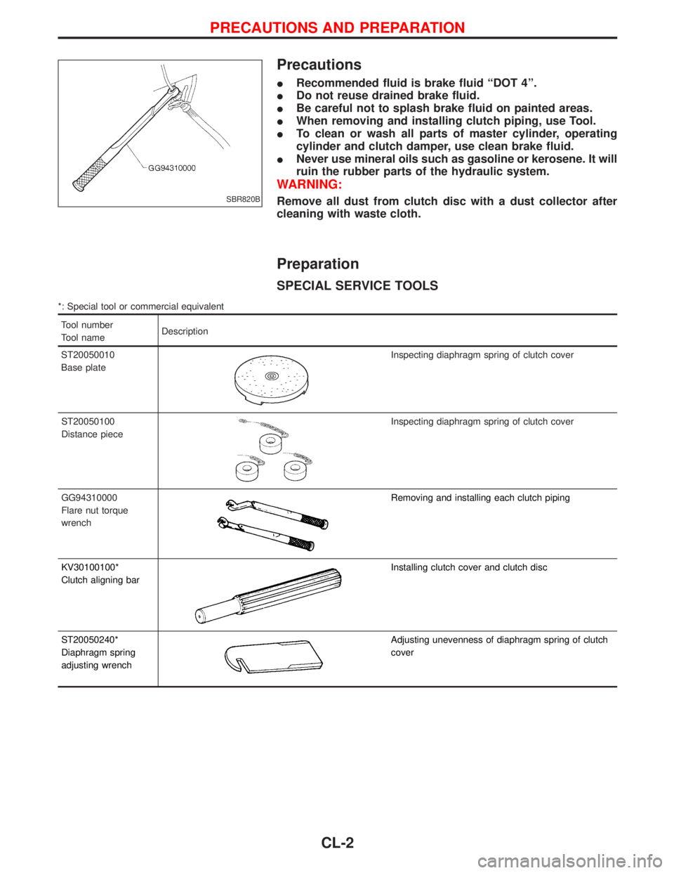
Precautions
IRecommended fluid is brake fluid ªDOT 4º.
IDo not reuse drained brake fluid.
IBe careful not to splash brake fluid on painted areas.
IWhen removing and installing clutch piping, use Tool.
ITo clean or wash all parts of master cylinder, operating
cylinder and clutch damper, use clean brake fluid.
INever use mineral oils such as gasoline or kerosene. It will
ruin the rubber parts of the hydraulic system.
WARNING:
Remove all dust from clutch disc with a dust collector after
cleaning with waste cloth.
Preparation
SPECIAL SERVICE TOOLS
*: Special tool or commercial equivalent
Tool number
Tool nameDescription
ST20050010
Base plate
Inspecting diaphragm spring of clutch cover
ST20050100
Distance piece
Inspecting diaphragm spring of clutch cover
GG94310000
Flare nut torque
wrench
Removing and installing each clutch piping
KV30100100*
Clutch aligning bar
Installing clutch cover and clutch disc
ST20050240*
Diaphragm spring
adjusting wrench
Adjusting unevenness of diaphragm spring of clutch
cover
SBR820B
PRECAUTIONS AND PREPARATION
CL-2
Page 391 of 1767
![NISSAN TERRANO 2002 Service Repair Manual c. Install the tightening bolt [Part No.: 81-20620-28, thread diam-
eter: M6, under head: 20 mm (0.79 in), pitch: 1.0 mm (0.039 in)]
to the idler gear tightening bolt hole, and tighten to the speci-
f](/manual-img/5/57393/w960_57393-390.png "NISSAN TERRANO 2002 Service Repair Manual c. Install the tightening bolt [Part No.: 81-20620-28, thread diam-
eter: M6, under head: 20 mm (0.79 in), pitch: 1.0 mm (0.039 in)]
to the idler gear tightening bolt hole, and tighten to the speci-
f")
c. Install the tightening bolt [Part No.: 81-20620-28, thread diam-
eter: M6, under head: 20 mm (0.79 in), pitch: 1.0 mm (0.039 in)]
to the idler gear tightening bolt hole, and tighten to the speci-
fied torque:
: 2.5 - 3.4 N×m (0.25 - 0.35 kg-m, 22 - 30 in-lb)
CAUTION:
ITo protect the idler gear from damage, do not use the sub-
stitute part for the tightening bolt.
IHereafter, do not turn the crankshaft to avoid hitting tight-
ening bolt head against the gear case.
IDo not remove the idler gear tightening bolt before instal-
lations of the timing chain and related parts are completed.
7. Make mating marks on the cam sprocket, fuel injection pump
sprocket, and timing chain with paint.
8. Make mating marks on the fuel injection pump gear and idler
gear with paint.
9. Remove the chain tensioner.
(1) Loosen the upper and lower installation bolts.
(2) While holding the chain tensioner by hand, remove the upper
installation bolt to release the spring tension.
(3) Remove the lower installation bolt first, and then the chain ten-
sioner.
ISince the chain tensioner does not have a mechanism to pre-
vent the plunger pop-out, watch out for the fall of the plunger
and spring. (Return prevention mechanism is available.)
10. Remove the timing chain slack guide.
11. Remove the cam sprocket and timing chain at the same time.
IMake mating marks on each sprocket and timing chain.
IHold the hexagon head of the camshaft on the exhaust mani-
fold side, and loosen the cam sprocket installation bolt.
CAUTION:
Do not loosen the installation bolt using a chain tension.
12. Remove the fuel injection pump sprocket and gear as an
assembly.
IFix the fuel injection pump gear with the pulley holder (SST),
and loosen the installation bolt for removal.
ITry not to move the pump shaft when removing.
IConnect the sprocket and gear with a dowel pin, and tighten
them together with the installation bolt.
JEF263Z
JEF264Z
JEF265Z
JEF266Z
JEF267Z
BASIC SERVICE PROCEDUREZD30DDTi
Electronic Control Fuel Injection Pump (Cont'd)
EC-29