Page 132 of 1767
f. Remove needle bearing from transmission case.
20. Remove rear side clutch and gear components.
a. Remove front internal gear.
b. Remove bearing race from front internal gear.
c. Remove needle bearing from rear internal gear.
d. Remove rear internal gear, forward clutch hub and overrun
clutch hub as a set from transmission case.
SAT033B
SAT954A
SAT110B
SAT111B
SAT951A
DISASSEMBLY
Disassembly (Cont'd)
AT-130
Page 133 of 1767
e. Remove needle bearing from overrun clutch hub.
f. Remove overrun clutch hub from rear internal gear and forward
clutch hub.
g. Remove thrust washer from overrun clutch hub.
h. Remove forward clutch assembly from transmission case.
21. Remove band servo and accumulator components.
a. Remove band servo retainer from transmission case.
b. Apply compressed air to oil hole until band servo piston comes
out of transmission case.
IHold piston with a rag and gradually direct air to oil hole.
c. Remove return springs.
SAT148G
SAT036B
SAT037B
SAT038B
SAT039B
DISASSEMBLY
Disassembly (Cont'd)
AT-131
Page 141 of 1767
DISASSEMBLY
1. Remove solenoids.
a. Remove torque converter clutch solenoid valve and side plate
from lower body.
b. Remove O-ring from solenoid.
c. Remove line pressure solenoid valve from upper body.
d. Remove O-ring from solenoid.
e. Remove 3-unit solenoid assembly from upper body.
f. Remove O-rings from solenoids.
2. Disassemble upper and lower bodies.
a. Place upper body facedown, and remove bolts, reamer bolts
and support plates.
b. Remove lower body, separator plate and separate gasket as a
unit from upper body.
IBe careful not to drop pilot filter, orifice check valve, spring
and steel balls.
c. Place lower body facedown, and remove separate gasket and
separator plate.
d. Remove pilot filter, orifice check valve and orifice check spring.
SAT194B
SAT667A
SAT043G
SAT195B
SAT670A
REPAIR FOR COMPONENT PARTS
Control Valve Assembly (Cont'd)
AT-139
Page 143 of 1767
Pilot filter
ICheck to make sure that filter is not clogged or damaged.
Torque converter clutch solenoid valve
ICheck that filter is not clogged or damaged.
IMeasure resistance. Refer to ªComponent Inspectionº, AT-84.
Line pressure solenoid valve
ICheck that filter is not clogged or damaged.
IMeasure resistance. Refer to ªComponent Inspectionº, AT-86.
3-unit solenoid assembly (Overrun clutch solenoid
valve and shift solenoid valves A and B)
IMeasure resistance of each solenoid. Refer to ªComponent
Inspectionº, AT-64, AT-67, AT-70.
A/T fluid temperature sensor
IMeasure resistance. Refer to ªComponent Inspectionº, AT-78.
ASSEMBLY
1. Install upper and lower bodies.
a. Place oil circuit of upper body face up. Install steel balls in their
proper positions.
SAT676A
SAT149G
SAT095B
SAT169BA
SAT671A
REPAIR FOR COMPONENT PARTS
Control Valve Assembly (Cont'd)
AT-141
Page 145 of 1767
g. Install and temporarily tighten bolts and tube brackets in their
proper locations.
Bolt length and location:
Bolt symbolqaqbqcqd
Bolt length mm (in)70
(2.76)50
(1.97)33
(1.30)27
(1.06)
2. Install solenoids.
a. Attach O-ring and install torque converter clutch solenoid valve
and side plates onto lower body.
b. Attach O-rings and install 3-unit solenoids assembly onto upper
body.
c. Attach O-ring and install line pressure solenoid valve onto
upper body.
3. Tighten all bolts.
SAT199BA
SAT200B
SAT150G
REPAIR FOR COMPONENT PARTS
Control Valve Assembly (Cont'd)
AT-143
Page 153 of 1767
Reverse Clutch
DISASSEMBLY
1. Check operation of reverse clutch.
a. Install seal ring onto oil pump cover and install reverse clutch.
Apply compressed air to oil hole.
b. Check to see that retaining plate moves to snap ring.
c. If retaining plate does not contact snap ring,
ID-ring might be damaged.
IOil seal might be damaged.
IFluid might be leaking past piston check ball.
2. Remove drive plates, driven plates, retaining plate, dish plate
and snap ring.
NAT296
SAT841A
SAT842A
REPAIR FOR COMPONENT PARTS
AT-151
Page 154 of 1767

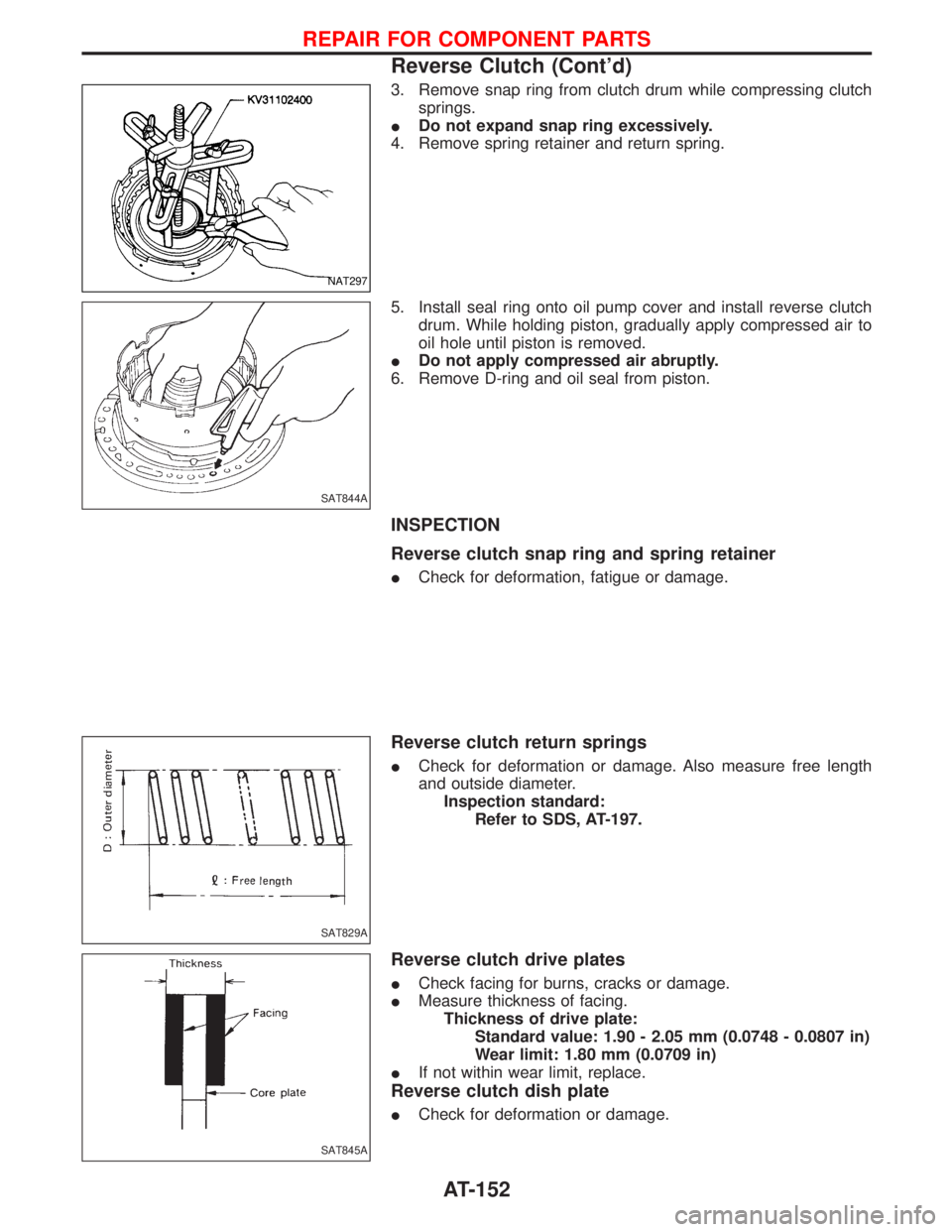
3. Remove snap ring from clutch drum while compressing clutch
springs.
IDo not expand snap ring excessively.
4. Remove spring retainer and return spring.
5. Install seal ring onto oil pump cover and install reverse clutch
drum. While holding piston, gradually apply compressed air to
oil hole until piston is removed.
IDo not apply compressed air abruptly.
6. Remove D-ring and oil seal from piston.
INSPECTION
Reverse clutch snap ring and spring retainer
ICheck for deformation, fatigue or damage.
Reverse clutch return springs
ICheck for deformation or damage. Also measure free length
and outside diameter.
Inspection standard:
Refer to SDS, AT-197.
Reverse clutch drive plates
ICheck facing for burns, cracks or damage.
IMeasure thickness of facing.
Thickness of drive plate:
Standard value: 1.90 - 2.05 mm (0.0748 - 0.0807 in)
Wear limit: 1.80 mm (0.0709 in)
IIf not within wear limit, replace.
Reverse clutch dish plate
ICheck for deformation or damage.
NAT297
SAT844A
SAT829A
SAT845A
REPAIR FOR COMPONENT PARTS
Reverse Clutch (Cont'd)
AT-152
Page 155 of 1767
Reverse clutch piston
IShake piston to assure that balls are not seized.
IApply compressed air to check ball oil hole opposite the return
spring. Make sure there is no air leakage.
IAlso apply compressed air to oil hole on return spring side to
assure that air leaks past ball.
ASSEMBLY
1. Install D-ring and oil seal on piston.
IApply ATF to both parts.
2. Install piston assembly by turning it slowly and evenly.
IApply ATF to inner surface of drum.
3. Install return springs and spring retainer.
4. Install snap ring while compressing clutch springs.
SAT846A
SAT847A
SAT848A
SAT849A
NAT297
REPAIR FOR COMPONENT PARTS
Reverse Clutch (Cont'd)
AT-153