Page 107 of 1767

14. A/T Does Not Shift: D3®D4
SYMPTOM:
IA/T does not shift from D3to D4at the specified speed.
IA/T must be warm before D
3to D4shift will occur.
Are 10. Vehicle Does Not Creep Forward
In ªDº, ª2º Or ª1º Position and 11. Vehicle
Cannot Be Started From D
1OK?
Ye s
ENo
Go to 10. Vehicle Does
Not Creep Forward In ªDº,
ª2º Or ª1º Position and 11.
Vehicle Cannot Be Started
From D
1, AT-101, AT-102.
Does self-diagnosis, after cruise test,
show damage to any of the following
circuits?
IPark/neutral position switch
IOverdrive control switch
IA/T fluid temperature sensor
IVehicle speed sensor×A/T (Revolu-
tion sensor)
IShift solenoid valve A or B
IVehicle speed sensor×MTR
No
EYe s
Check damaged circuit.
Refer to AT-50, AT-54,
AT-63, AT-66 or AT-88.
Check throttle (accelerator) position sen-
sor. Refer to EC section [TROUBLE
DIAGNOSIS FOR ªTHROTTLE (ACCEL)
POSI SENº].
OK
ENG
Repair or replace throttle
(accelerator) position sen-
sor.
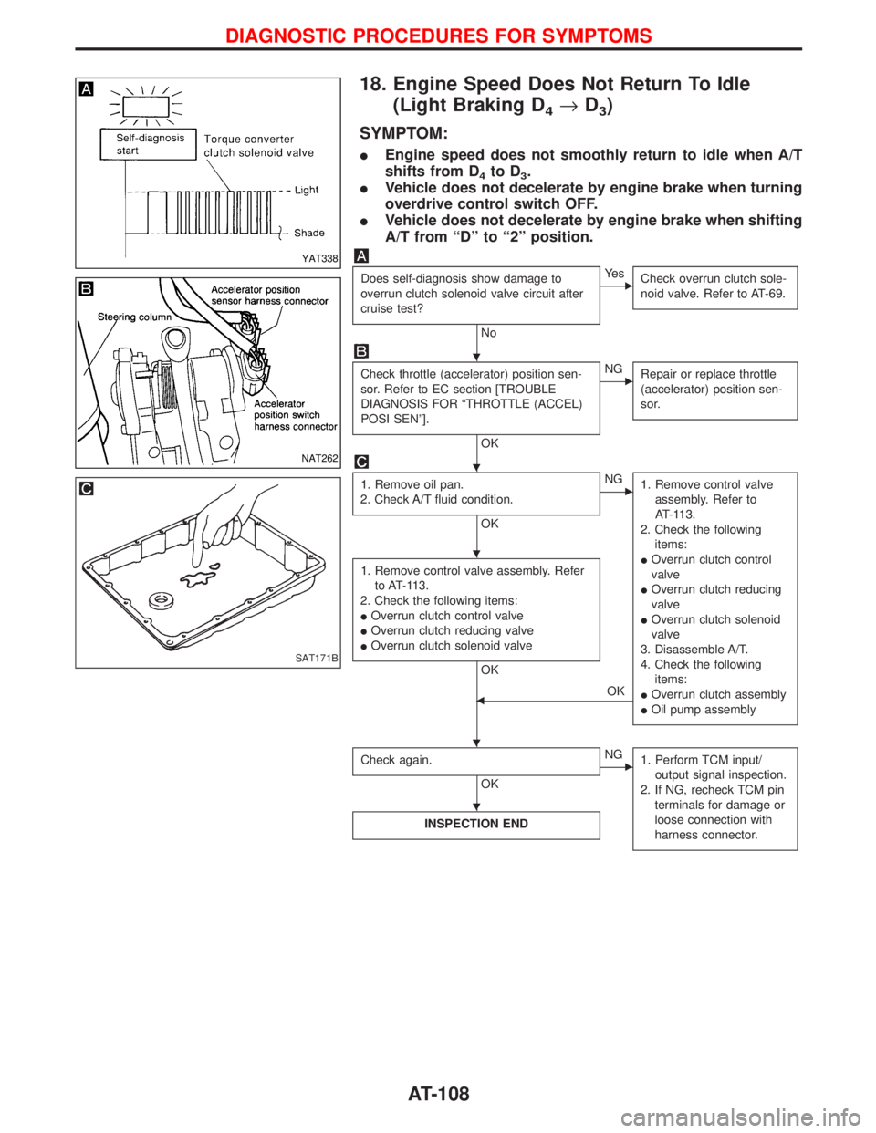
1. Remove oil pan.
2. Check A/T fluid condition.
OK
ENG
1. Remove control valve
assembly. Refer to
AT-113.
2. Check the following
items:
IShift valve B
IOverrun clutch control
valve
IShift solenoid valve B
IPilot valve
IPilot filter
3. Disassemble A/T.
4. Check the following
items:
IServo piston assembly
IBrake band
ITorque converter
IOil pump assembly
1. Remove control valve assembly. Refer
to AT-113.
2. Check the following items:
IShift valve B
IOverrun clutch control valve
IShift solenoid valve B
IPilot valve
IPilot filter
OK
FOK
Check again.
OK
ENG
1. Perform TCM input/
output signal inspection.
2. If NG, recheck TCM pin
terminals for damage or
loose connection with
harness connector.
INSPECTION END
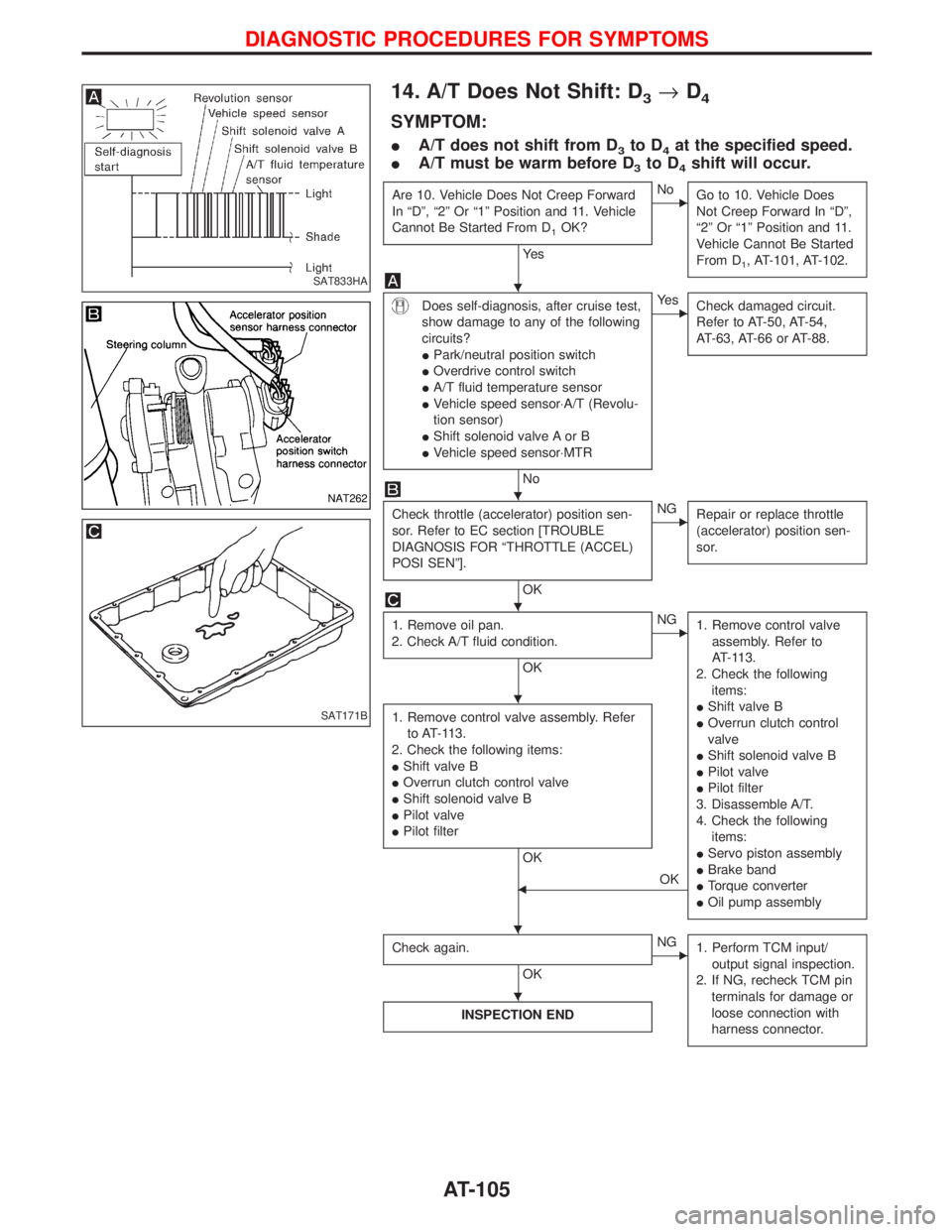
SAT833HA
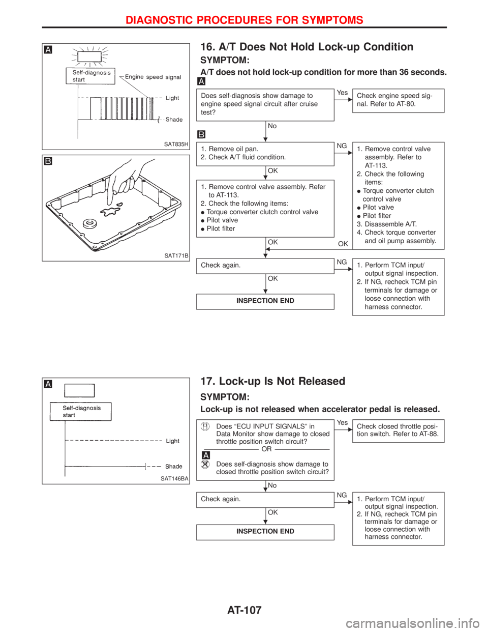
NAT262
SAT171B
H
H
H
H
H H
H
DIAGNOSTIC PROCEDURES FOR SYMPTOMS
AT-105
Page 108 of 1767
15. A/T Does Not Perform Lock-up
SYMPTOM:
A/T does not perform lock-up at the specified speed.
Does self-diagnosis show damage to
torque converter clutch solenoid valve
after cruise test?
No
EYe s
Check torque converter
clutch solenoid valve.
Refer to AT-72.
Check throttle (accelerator) position sen-
sor. Refer to EC section [TROUBLE
DIAGNOSIS FOR ªTHROTTLE (ACCEL)
POSI SENº].
OK
ENG
Repair or replace throttle
(accelerator) position sen-
sor.
1. Remove control valve. Refer to AT-113.
2. Check following items:
ITorque converter clutch control valve
ITorque converter relief valve
ITorque converter clutch solenoid valve
IPilot valve
IPilot filter
OK
ENG
Repair or replace dam-
aged parts.
Check again.
OK
ENG
1. Perform TCM input/
output signal inspection.
2. If NG, recheck TCM pin
terminals for damage or
loose connection with
harness connector.
INSPECTION END
SAT844H
NAT262
H
H
H H
H
DIAGNOSTIC PROCEDURES FOR SYMPTOMS
AT-106
Page 109 of 1767

16. A/T Does Not Hold Lock-up Condition
SYMPTOM:
A/T does not hold lock-up condition for more than 36 seconds.
Does self-diagnosis show damage to
engine speed signal circuit after cruise
test?
No
EYe s
Check engine speed sig-
nal. Refer to AT-80.
1. Remove oil pan.
2. Check A/T fluid condition.
OK
ENG
1. Remove control valve
assembly. Refer to
AT-113.
2. Check the following
items:
ITorque converter clutch
control valve
IPilot valve
IPilot filter
3. Disassemble A/T.
4. Check torque converter
and oil pump assembly.
1. Remove control valve assembly. Refer
to AT-113.
2. Check the following items:
ITorque converter clutch control valve
IPilot valve
IPilot filter
OKFOK
Check again.
OK
ENG
1. Perform TCM input/
output signal inspection.
2. If NG, recheck TCM pin
terminals for damage or
loose connection with
harness connector.
INSPECTION END
17. Lock-up Is Not Released
SYMPTOM:
Lock-up is not released when accelerator pedal is released.
Does ªECU INPUT SIGNALSº in
Data Monitor show damage to closed
throttle position switch circuit?
-----------------------------------------------------------------------------------------------------------------------OR -----------------------------------------------------------------------------------------------------------------------
Does self-diagnosis show damage to
closed throttle position switch circuit?
No
EYe s
Check closed throttle posi-
tion switch. Refer to AT-88.
Check again.
OK
ENG
1. Perform TCM input/
output signal inspection.
2. If NG, recheck TCM pin
terminals for damage or
loose connection with
harness connector.
INSPECTION END
SAT835H
SAT171B
SAT146BA
H
H
H H
H
H
H
DIAGNOSTIC PROCEDURES FOR SYMPTOMS
AT-107
Page 110 of 1767

18. Engine Speed Does Not Return To Idle
(Light Braking D
4®D3)
SYMPTOM:
IEngine speed does not smoothly return to idle when A/T
shifts from D
4to D3.
IVehicle does not decelerate by engine brake when turning
overdrive control switch OFF.
IVehicle does not decelerate by engine brake when shifting
A/T from ªDº to ª2º position.
Does self-diagnosis show damage to
overrun clutch solenoid valve circuit after
cruise test?
No
EYe s
Check overrun clutch sole-
noid valve. Refer to AT-69.
Check throttle (accelerator) position sen-
sor. Refer to EC section [TROUBLE
DIAGNOSIS FOR ªTHROTTLE (ACCEL)
POSI SENº].
OK
ENG
Repair or replace throttle
(accelerator) position sen-
sor.
1. Remove oil pan.
2. Check A/T fluid condition.
OK
ENG
1. Remove control valve
assembly. Refer to
AT-113.
2. Check the following
items:
IOverrun clutch control
valve
IOverrun clutch reducing
valve
IOverrun clutch solenoid
valve
3. Disassemble A/T.
4. Check the following
items:
IOverrun clutch assembly
IOil pump assembly
1. Remove control valve assembly. Refer
to AT-113.
2. Check the following items:
IOverrun clutch control valve
IOverrun clutch reducing valve
IOverrun clutch solenoid valve
OK
FOK
Check again.
OK
ENG
1. Perform TCM input/
output signal inspection.
2. If NG, recheck TCM pin
terminals for damage or
loose connection with
harness connector.
INSPECTION END
YAT338
NAT262
SAT171B
H
H
H
H H
H
DIAGNOSTIC PROCEDURES FOR SYMPTOMS
AT-108
Page 125 of 1767
Disassembly
1. Drain ATF through drain plug.
2. Remove torque converter by holding it firmly and turning while
pulling straight out.
3. Check torque converter one-way clutch.
a. Insert Tool into spline of one-way clutch inner race.
b. Hook bearing support unitized with one-way clutch outer race
with suitable wire.
c. Check that one-way clutch inner race rotates only clockwise
with Tool while holding bearing support with wire.
4. Remove park/neutral position switch from transmission case.
5. Remove oil pan.
IAlways place oil pan straight down so that foreign par-
ticles inside will not move.
6. Place transmission into Tool with the control valve facing up.
SAT018B
NAT226
YAT339
SAT754I
NAT227
DISASSEMBLY
AT-123
Page 126 of 1767
7. Check foreign materials in oil pan to help determine cause of
malfunction. If the fluid is very dark, smells burned, or contains
foreign particles, the frictional material (clutches, band) may
need replacement. A tacky film that will not wipe clean indicates
varnish build up. Varnish can cause valves, servo, and clutches
to stick and may inhibit pump pressure.
IIf frictional material is detected, replace radiator after
repair of A/T. Refer to LC section (ªRadiatorº, ªENGINE
COOLING SYSTEMº).
8. Remove torque converter clutch solenoid valve and A/T fluid
temperature sensor connectors.
IBe careful not to damage connector.
9. Remove oil strainer.
a. Remove oil strainer from control valve assembly then remove
O-ring from oil strainer.
b. Check oil strainer screen for damage.
10. Remove control valve assembly.
a. Straighten terminal clips to free terminal cords then remove
terminal clips.
SAT171B
NAT228
SAT008B
SAT025B
SAT009B
DISASSEMBLY
Disassembly (Cont'd)
AT-124
Page 129 of 1767
15. Remove input shaft and oil pump gasket.
16. Remove brake band and band strut.
a. Loosen lock nut and remove band servo anchor end pin from
transmission case.
b. Remove brake band and band strut from transmission case.
c. Hold brake band in a circular shape with clip.
17. Remove front side clutch and gear components.
a. Remove clutch pack (reverse clutch, high clutch and front sun
gear) from transmission case.
SAT988A
SAT029B
SAT986A
SAT655
SAT030B
DISASSEMBLY
Disassembly (Cont'd)
AT-127
Page 130 of 1767
b. Remove front bearing race from clutch pack.
c. Remove rear bearing race from clutch pack.
d. Remove front planetary carrier from transmission case.
e. Remove front needle bearing from front planetary carrier.
f. Remove rear bearing from front planetary carrier.
g. Remove rear sun gear from transmission case.
18. Remove adapter case.
a. Remove adapter case from transmission case.
b. Remove adapter case gasket from transmission case.
SAT113B
SAT031B
SAT968A
SAT974A
SAT755I
DISASSEMBLY
Disassembly (Cont'd)
AT-128