2002 NISSAN TERRANO clutch
[x] Cancel search: clutchPage 46 of 1767
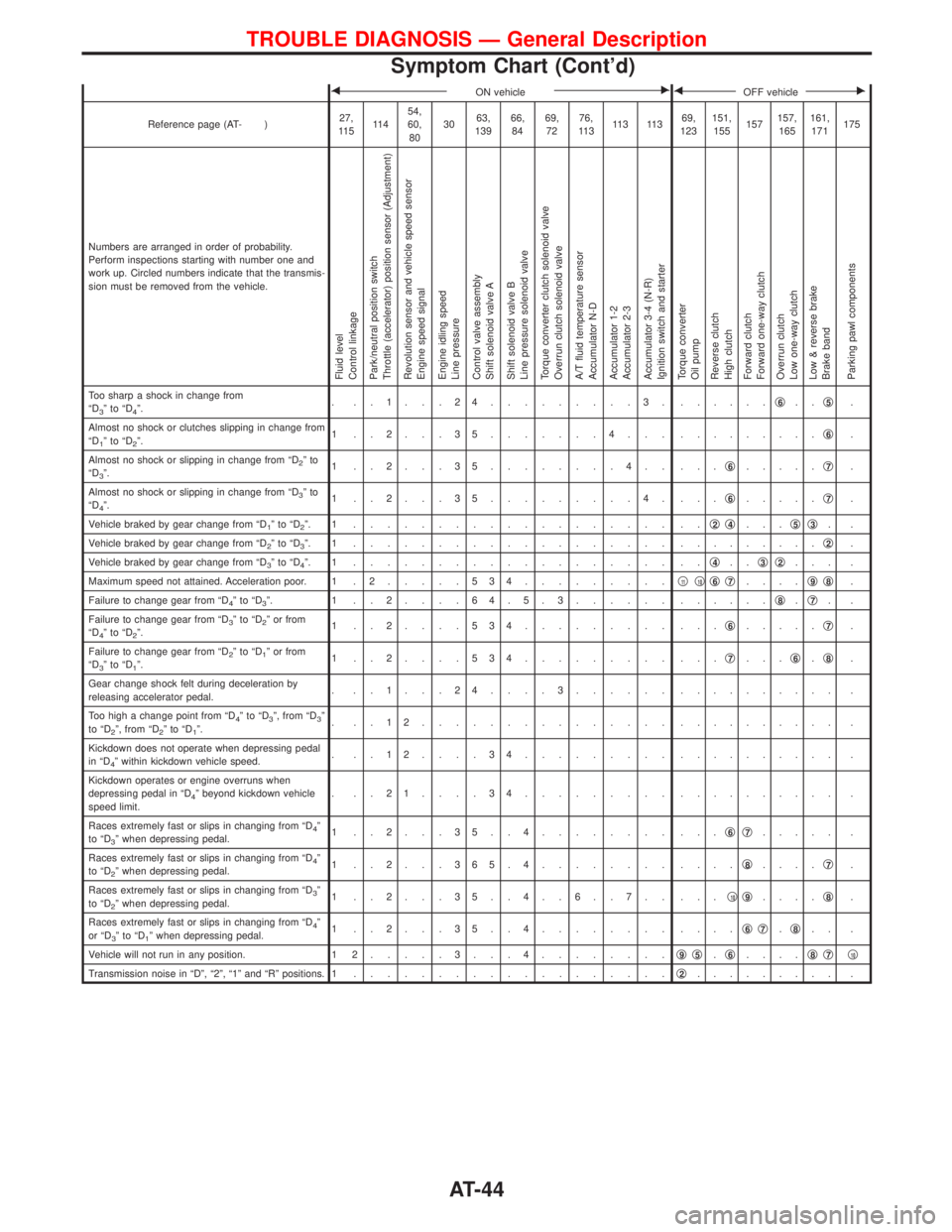
FON vehicleEFOFF vehicleE
Reference page (AT- )27,
11 511 454,
60,
803063,
13966,
8469,
7276,
11 311 3 11 369,
123151,
155157157,
165161,
171175
Numbers are arranged in order of probability.
Perform inspections starting with number one and
work up. Circled numbers indicate that the transmis-
sion must be removed from the vehicle.
Fluid level
Control linkage
Park/neutral position switch
Throttle (accelerator) position sensor (Adjustment)
Revolution sensor and vehicle speed sensor
Engine speed signal
Engine idling speed
Line pressure
Control valve assembly
Shift solenoid valve A
Shift solenoid valve B
Line pressure solenoid valve
Torque converter clutch solenoid valve
Overrun clutch solenoid valve
A/T fluid temperature sensor
Accumulator N-D
Accumulator 1-2
Accumulator 2-3
Accumulator 3-4 (N-R)
Ignition switch and starter
Torque converter
Oil pump
Reverse clutch
High clutch
Forward clutch
Forward one-way clutch
Overrun clutch
Low one-way clutch
Low & reverse brake
Brake band
Parking pawl components
Too sharp a shock in change from
ªD3ºtoªD4º.. ..1...24.........3. ......q6..q5.
Almost no shock or clutches slipping in change from
ªD
1ºtoªD2º.1 ..2...35.......4... .........q6.
Almost no shock or slipping in change from ªD
2ºto
ªD3º.1 ..2...35........4.. ...q6.....q7.
Almost no shock or slipping in change from ªD
3ºto
ªD4º.1 ..2...35.........4. ...q6.....q7.
Vehicle braked by gear change from ªD
1ºtoªD2º. 1 ................... ..q2q4...q5q3..
Vehicle braked by gear change from ªD
2ºtoªD3º. 1 ................... .........q2.
Vehicle braked by gear change from ªD
3ºtoªD4º. 1 ................... ..q4..q3q2... .
Maximum speed not attained. Acceleration poor. 1 . 2.....534.........q
11q10q6q7....q9q8.
Failure to change gear from ªD
4ºtoªD3º. 1 ..2....64.5.3...... ......q8.q7..
Failure to change gear from ªD
3ºtoªD2º or from
ªD4ºtoªD2º.1 ..2....534......... ...q6.....q7.
Failure to change gear from ªD
2ºtoªD1º or from
ªD3ºtoªD1º.1 ..2....534......... ...q7...q6.q8.
Gear change shock felt during deceleration by
releasing accelerator pedal.. ..1...24....3...... .......... .
Too high a change point from ªD
4ºtoªD3º, from ªD3º
to ªD2º, from ªD2ºtoªD1º.. ..12............... .......... .
Kickdown does not operate when depressing pedal
in ªD
4º within kickdown vehicle speed.. ..12....34......... .......... .
Kickdown operates or engine overruns when
depressing pedal in ªD
4º beyond kickdown vehicle
speed limit.. ..21....34......... .......... .
Races extremely fast or slips in changing from ªD
4º
to ªD3º when depressing pedal.1 ..2...35..4........ ...q6q7..... .
Races extremely fast or slips in changing from ªD
4º
to ªD2º when depressing pedal.1 ..2...365.4........ ....q8....q7.
Races extremely fast or slips in changing from ªD
3º
to ªD2º when depressing pedal.1 ..2...35..4..6..7.. ...q10q9....q8.
Races extremely fast or slips in changing from ªD
4º
or ªD3ºtoªD1º when depressing pedal.1 ..2...35..4........ ....q6q7.q8.. .
Vehicle will not run in any position. 1 2.....3...4........q
9q5.q6....q8q7q10
Transmission noise in ªDº, ª2º, ª1º and ªRº positions. 1...................q2......... .
TROUBLE DIAGNOSIS Ð General Description
Symptom Chart (Cont'd)
AT-44
Page 47 of 1767
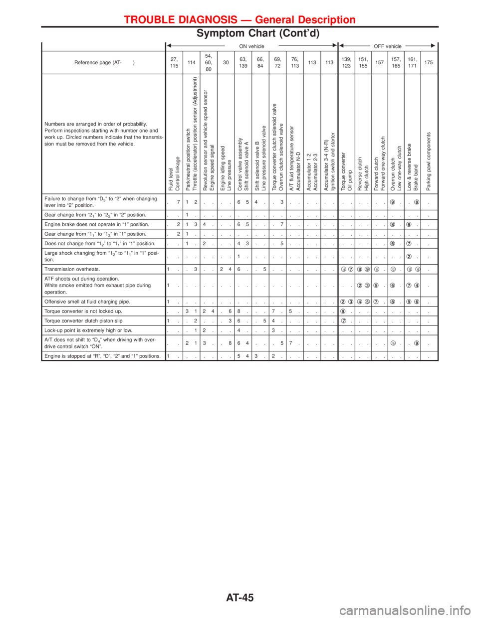
FON vehicleEFOFF vehicleE
Reference page (AT- )27,
11 511 454,
60,
803063,
13966,
8469,
7276,
11 311 3 11 3139,
123151,
155157157,
165161,
171175
Numbers are arranged in order of probability.
Perform inspections starting with number one and
work up. Circled numbers indicate that the transmis-
sion must be removed from the vehicle.
Fluid level
Control linkage
Park/neutral position switch
Throttle (accelerator) position sensor (Adjustment)
Revolution sensor and vehicle speed sensor
Engine speed signal
Engine idling speed
Line pressure
Control valve assembly
Shift solenoid valve A
Shift solenoid valve B
Line pressure solenoid valve
Torque converter clutch solenoid valve
Overrun clutch solenoid valve
A/T fluid temperature sensor
Accumulator N-D
Accumulator 1-2
Accumulator 2-3
Accumulator 3-4 (N-R)
Ignition switch and starter
Torque converter
Oil pump
Reverse clutch
High clutch
Forward clutch
Forward one-way clutch
Overrun clutch
Low one-way clutch
Low & reverse brake
Brake band
Parking pawl components
Failure to change from ªD3º to ª2º when changing
lever into ª2º position.. 712....654..3...... ......q9..q8.
Gear change from ª2
1ºtoª22º in ª2º position. . . 1................. .......... .
Engine brake does not operate in ª1º position. .2134 . . . 65 . . . 7...... ......q
8.q9..
Gear change from ª1
1ºtoª12º in ª1º position. . 2 1................. .......... .
Does not change from ª1
2ºtoª11º in ª1º position. . . 1 . 2 . . . 4 3 . . . 5...... ......q6.q7..
Large shock changing from ª1
2ºtoª11º in ª1º posi-
tion.. .......1........... ........q2..
Transmission overheats. 1 . . 3 . . 2 4 6 . . 5........q
14q7q8q9q11.q12.q13q10.
ATF shoots out during operation.
White smoke emitted from exhaust pipe during
operation.1 ................... ..q
2q3q5.q6.q7q4.
Offensive smell at fluid charging pipe. 1...................q
2q3q4q5q7.q8.q9q6.
Torque converter is not locked up. . .3124 . 68 . . . 7 . 5.....q
9......... .
Torque converter clutch piston slip 1 . . 2 . . . 3 6 . . 5 4.......q
7......... .
Lock-up point is extremely high or low. . . . 1 2 . . . 4 . . . 3....... .......... .
A/T does not shift to ªD
4º when driving with over-
drive control switch ªONº.. .213..864...57..... ......q10..q9.
Engine is stopped at ªRº, ªDº, ª2º and ª1º positions. 1.......543.2....... .......... .
TROUBLE DIAGNOSIS Ð General Description
Symptom Chart (Cont'd)
AT-45
Page 48 of 1767
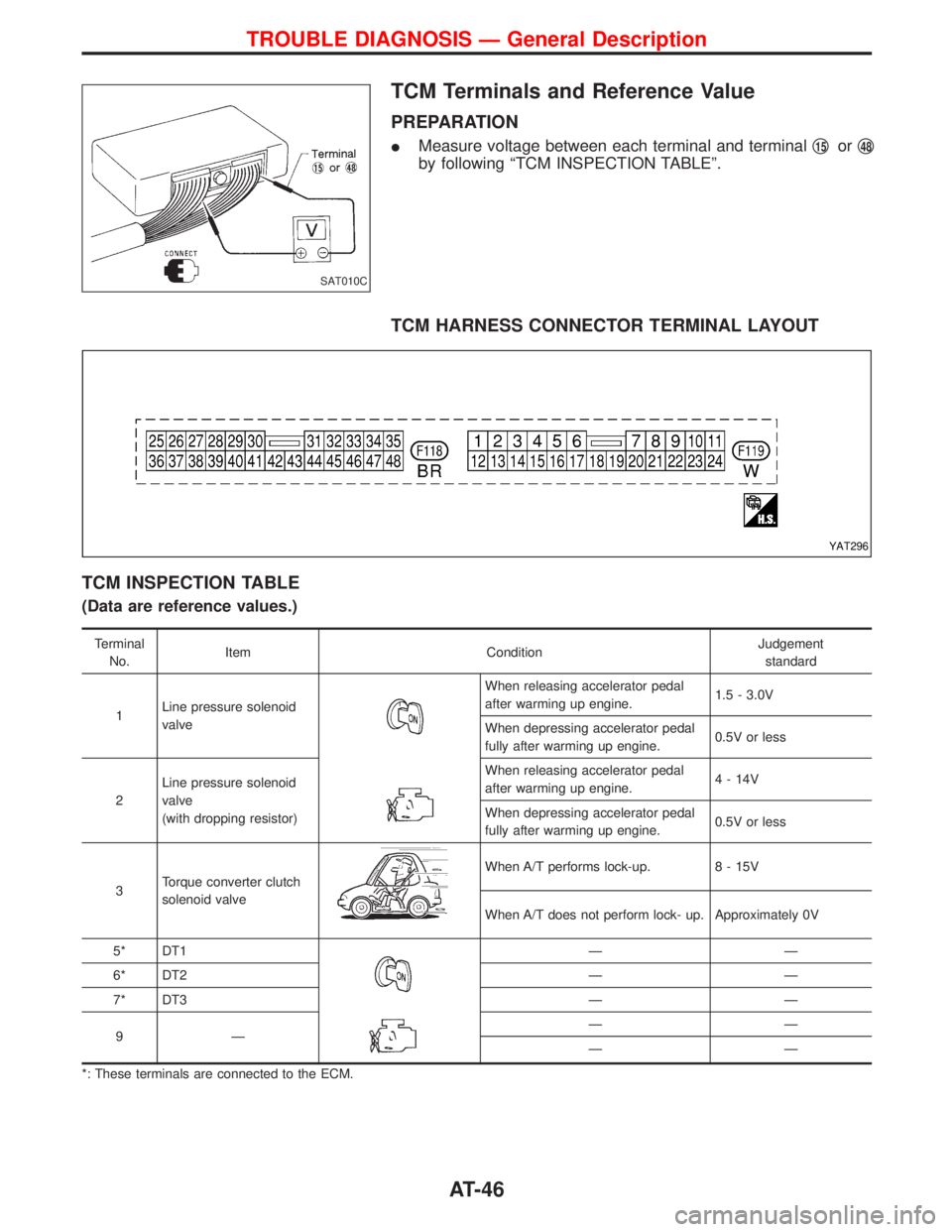
TCM Terminals and Reference Value
PREPARATION
IMeasure voltage between each terminal and terminalq15orq48
by following ªTCM INSPECTION TABLEº.
TCM HARNESS CONNECTOR TERMINAL LAYOUT
TCM INSPECTION TABLE
(Data are reference values.)
Terminal
No.Item ConditionJudgement
standard
1Line pressure solenoid
valve
When releasing accelerator pedal
after warming up engine.1.5 - 3.0V
When depressing accelerator pedal
fully after warming up engine.0.5V or less
2Line pressure solenoid
valve
(with dropping resistor)When releasing accelerator pedal
after warming up engine.4 - 14V
When depressing accelerator pedal
fully after warming up engine.0.5V or less
3Torque converter clutch
solenoid valve
When A/T performs lock-up. 8 - 15V
When A/T does not perform lock- up. Approximately 0V
5* DT1
ÐÐ
6* DT2 Ð Ð
7* DT3 Ð Ð
9ÐÐÐ
ÐÐ
*: These terminals are connected to the ECM.
SAT010C
YAT296
TROUBLE DIAGNOSIS Ð General Description
AT-46
Page 49 of 1767
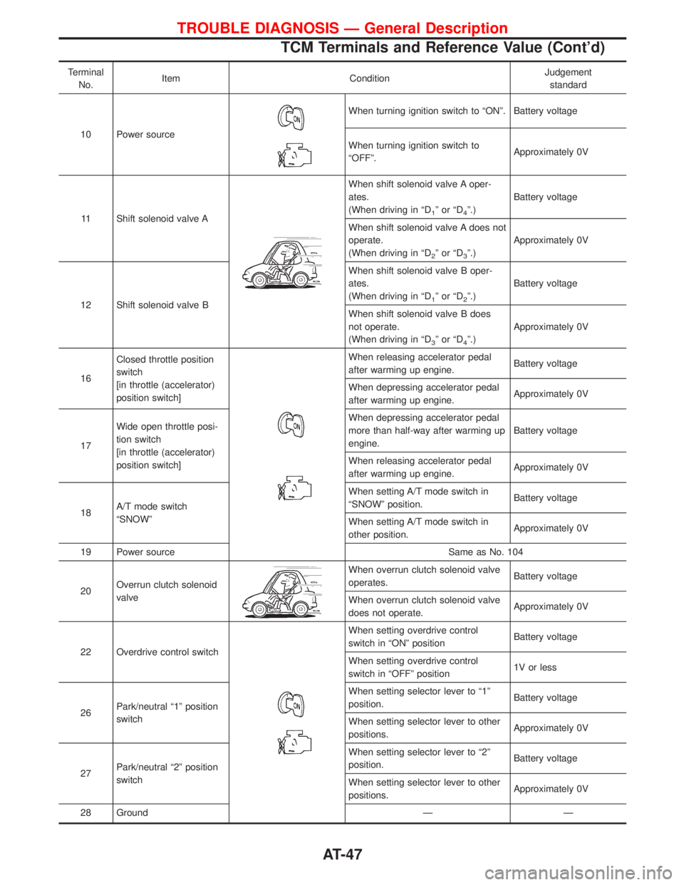
Terminal
No.Item ConditionJudgement
standard
10 Power source
When turning ignition switch to ªONº. Battery voltage
When turning ignition switch to
ªOFFº.Approximately 0V
11 Shift solenoid valve A
When shift solenoid valve A oper-
ates.
(When driving in ªD
1ºorªD4º.)Battery voltage
When shift solenoid valve A does not
operate.
(When driving in ªD
2ºorªD3º.)Approximately 0V
12 Shift solenoid valve BWhen shift solenoid valve B oper-
ates.
(When driving in ªD
1ºorªD2º.)Battery voltage
When shift solenoid valve B does
not operate.
(When driving in ªD
3ºorªD4º.)Approximately 0V
16Closed throttle position
switch
[in throttle (accelerator)
position switch]
When releasing accelerator pedal
after warming up engine.Battery voltage
When depressing accelerator pedal
after warming up engine.Approximately 0V
17Wide open throttle posi-
tion switch
[in throttle (accelerator)
position switch]When depressing accelerator pedal
more than half-way after warming up
engine.Battery voltage
When releasing accelerator pedal
after warming up engine.Approximately 0V
18A/T mode switch
ªSNOWºWhen setting A/T mode switch in
ªSNOWº position.Battery voltage
When setting A/T mode switch in
other position.Approximately 0V
19 Power source Same as No. 104
20Overrun clutch solenoid
valve
When overrun clutch solenoid valve
operates.Battery voltage
When overrun clutch solenoid valve
does not operate.Approximately 0V
22 Overdrive control switch
When setting overdrive control
switch in ªONº positionBattery voltage
When setting overdrive control
switch in ªOFFº position1V or less
26Park/neutral ª1º position
switchWhen setting selector lever to ª1º
position.Battery voltage
When setting selector lever to other
positions.Approximately 0V
27Park/neutral ª2º position
switchWhen setting selector lever to ª2º
position.Battery voltage
When setting selector lever to other
positions.Approximately 0V
28 Ground Ð Ð
TROUBLE DIAGNOSIS Ð General Description
TCM Terminals and Reference Value (Cont'd)
AT-47
Page 70 of 1767

Wiring Diagram Ð AT Ð OVRCSV
YAT282
TROUBLE DIAGNOSIS FOR OVERRUN CLUTCH S/V
AT-68
Page 71 of 1767
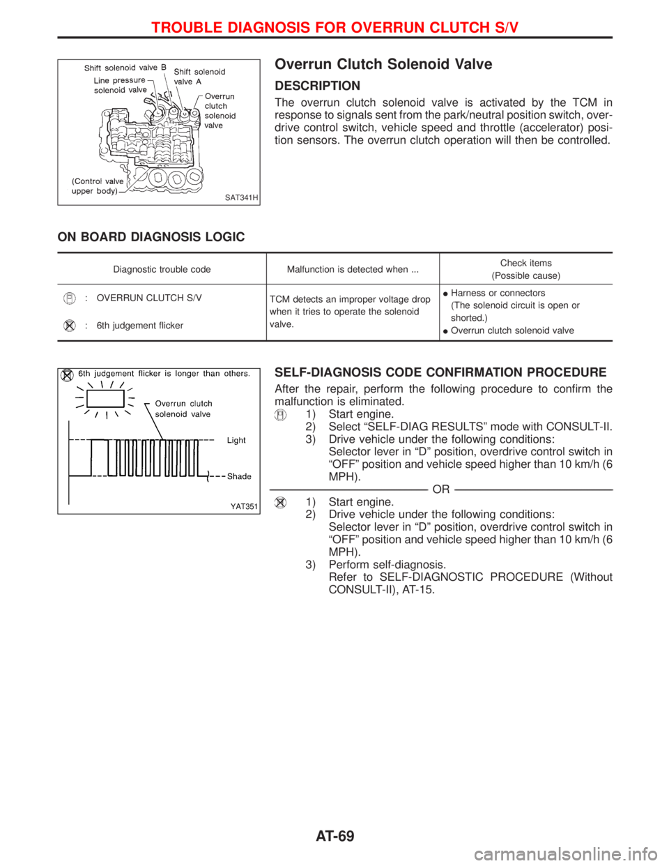
Overrun Clutch Solenoid Valve
DESCRIPTION
The overrun clutch solenoid valve is activated by the TCM in
response to signals sent from the park/neutral position switch, over-
drive control switch, vehicle speed and throttle (accelerator) posi-
tion sensors. The overrun clutch operation will then be controlled.
ON BOARD DIAGNOSIS LOGIC
Diagnostic trouble code Malfunction is detected when ...Check items
(Possible cause)
: OVERRUN CLUTCH S/V
TCM detects an improper voltage drop
when it tries to operate the solenoid
valve.IHarness or connectors
(The solenoid circuit is open or
shorted.)
IOverrun clutch solenoid valve
: 6th judgement flicker
SELF-DIAGNOSIS CODE CONFIRMATION PROCEDURE
After the repair, perform the following procedure to confirm the
malfunction is eliminated.
1) Start engine.
2) Select ªSELF-DIAG RESULTSº mode with CONSULT-II.
3) Drive vehicle under the following conditions:
Selector lever in ªDº position, overdrive control switch in
ªOFFº position and vehicle speed higher than 10 km/h (6
MPH).
------------------------------------------------------------------------------------------------------------------------------------------------------------------------------------------------------------------------------------------------------------OR------------------------------------------------------------------------------------------------------------------------------------------------------------------------------------------------------------------------------------------------------------
1) Start engine.
2) Drive vehicle under the following conditions:
Selector lever in ªDº position, overdrive control switch in
ªOFFº position and vehicle speed higher than 10 km/h (6
MPH).
3) Perform self-diagnosis.
Refer to SELF-DIAGNOSTIC PROCEDURE (Without
CONSULT-II), AT-15.
SAT341H
YAT351
TROUBLE DIAGNOSIS FOR OVERRUN CLUTCH S/V
AT-69
Page 72 of 1767
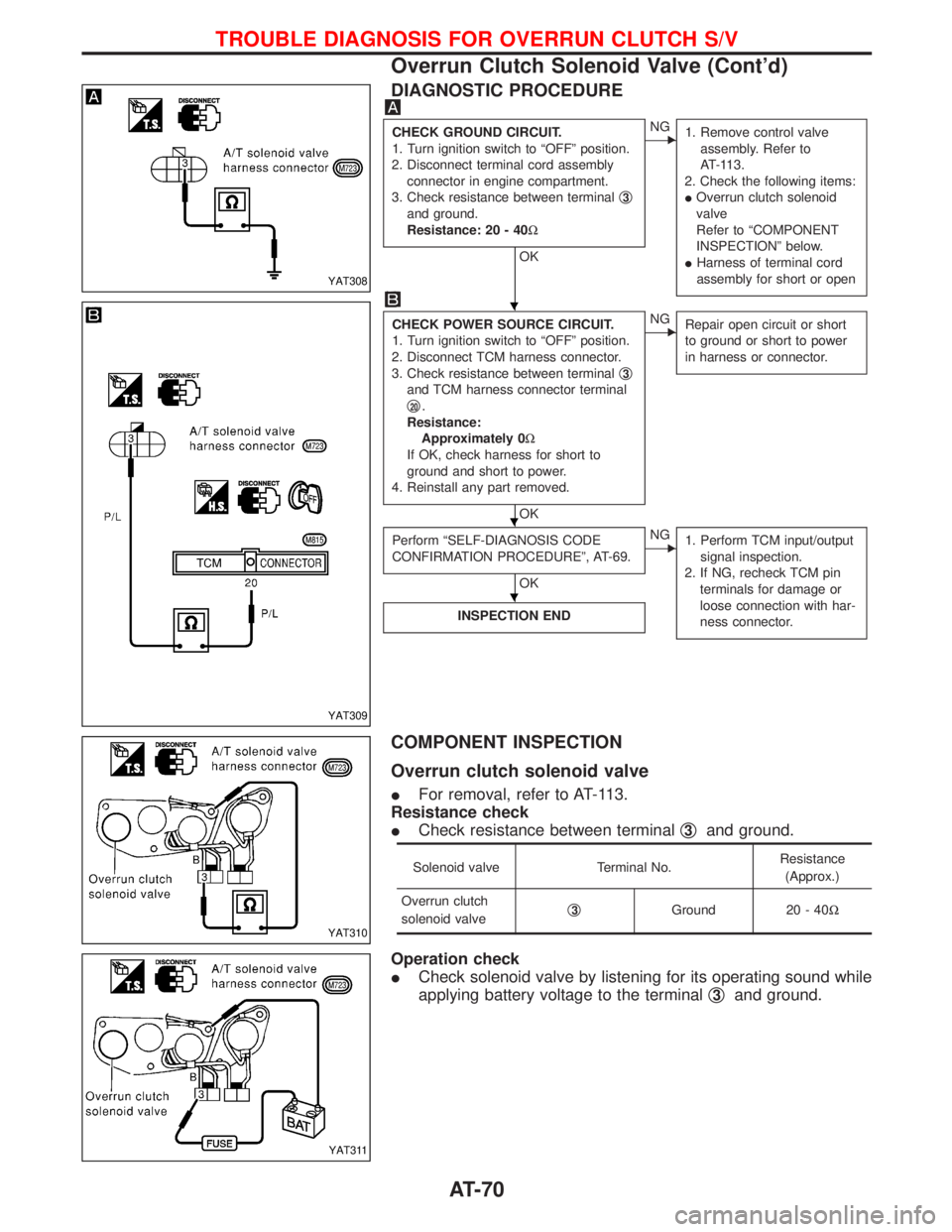
DIAGNOSTIC PROCEDURE
CHECK GROUND CIRCUIT.
1. Turn ignition switch to ªOFFº position.
2. Disconnect terminal cord assembly
connector in engine compartment.
3. Check resistance between terminalq
3
and ground.
Resistance: 20 - 40W
OK
ENG
1. Remove control valve
assembly. Refer to
AT-113.
2. Check the following items:
IOverrun clutch solenoid
valve
Refer to ªCOMPONENT
INSPECTIONº below.
IHarness of terminal cord
assembly for short or open
CHECK POWER SOURCE CIRCUIT.
1. Turn ignition switch to ªOFFº position.
2. Disconnect TCM harness connector.
3. Check resistance between terminalq
3
and TCM harness connector terminal
q
20.
Resistance:
Approximately 0W
If OK, check harness for short to
ground and short to power.
4. Reinstall any part removed.
OK
ENG
Repair open circuit or short
to ground or short to power
in harness or connector.
Perform ªSELF-DIAGNOSIS CODE
CONFIRMATION PROCEDUREº, AT-69.
OK
ENG
1. Perform TCM input/output
signal inspection.
2. If NG, recheck TCM pin
terminals for damage or
loose connection with har-
ness connector.
INSPECTION END
COMPONENT INSPECTION
Overrun clutch solenoid valve
IFor removal, refer to AT-113.
Resistance check
ICheck resistance between terminalq
3and ground.
Solenoid valve Terminal No.Resistance
(Approx.)
Overrun clutch
solenoid valveq
3Ground 20 - 40W
Operation check
ICheck solenoid valve by listening for its operating sound while
applying battery voltage to the terminalq
3and ground.
YAT308
YAT309
YAT310
YAT311
H
H
H
TROUBLE DIAGNOSIS FOR OVERRUN CLUTCH S/V
Overrun Clutch Solenoid Valve (Cont'd)
AT-70
Page 73 of 1767

Wiring Diagram Ð AT Ð TCV
YAT277
TROUBLE DIAGNOSIS FOR T/C CLUTCH SOL/V
AT-71