Page 1700 of 1767
Magnetic Switch Check
Magnetic Switch Check
IBefore starting to check, disconnect battery ground cable.
IDisconnect ªMº terminal of starter motor.
1. Continuity test (between ªSº terminal and switch body).
INo continuity ... Replace.
2. Continuity test (between ªSº terminal and ªMº terminal).
INo continuity ... Replace.
Pinion/Clutch Check
1. Check to see if pinion locks in one direction and rotates
smoothly in the opposite direction.
IIf it does not lock (or locks) in either direction or unusual
resistance is evident ... Replace.
2. Check pinion movement
IIf it is hard to move, apply grease or, if necessary, replace.
3. Check ball bearing.
Spin outer race of ball bearing to ensure that it turns smoothly
without binding.
IAbnormal resistance ... Replace.
SEL555E
SEL556E
YEL546D
YEL547D
YEL548D
STARTING SYSTEM
SC-19
Page 1701 of 1767
4. Inspect pinion teeth.
IReplace pinion if teeth are worn or damaged. (Also check
condition of ring gear teeth.)
5. Inspect reduction gear teeth.
IReplace reduction gear if teeth are worn of damaged.
(Also check condition of armature shaft gear teeth.)
Brush Check
BRUSH
Check wear of brush.
Wear limit length:
Refer to SDS (SC-30).
IExcessive wear ... Replace.
BRUSH HOLDER
1. Perform insulation test between brush holder (positive side)
and its base (negative side).
IContinuity exists ... Replace.
2. Check brush to see if it moves smoothly.
IIf brush holder is bent, replace it; if sliding surface is dirty,
clean.
Field Coil Check
1. Continuity test (between field coil positive terminal and positive
brushes).
INo continuity ... Replace field coil.
2. Insulation test (between field coil positive terminal and yoke).
IContinuity exists ... Replace field coil.
SEL014Z
YEL549D
YEL550D
SEL103E
STARTING SYSTEM
Pinion/Clutch Check (Cont'd)
SC-20
Page 1750 of 1767
Mainshaft
DISASSEMBLY
1. Check end play of front drive sprocket.
Standard:
0.2 - 0.35 mm (0.0079 - 0.0138 in)
If end play is beyond the maximum value, check front drive
sprocket and clutch gear for wear.
2. Remove retaining ring, speedometer drive gear and steel ball.
Be careful not to lose the steel ball.
3. Remove snap ring and spacer.
4. Press out front drive sprocket with mainshaft rear bearing and
clutch gear together.
5. Remove needle bearing.
6. Remove bearing retainer and then remove snap ring and
spacer.
SMT347A
YMT019
SMT290A
SMT291A
SMT292A
REPAIR FOR COMPONENT PARTS
TF-17
Page 1763 of 1767
f. Install 2-4 coupling sleeve with 2-4 shift fork.
Pay special attention to direction of coupling sleeve.
g. Install shifting inserts and spread spring.
Pay special attention to direction of shifting inserts.
h. Install baulk ring and then install clutch gear and mainshaft rear
bearing.
Place wooden block under mainshaft in order to protect main-
shaft front bearing.
i. Install spacer.
j. Select snap ring with proper thickness and install it.
Allowable clearance between snap ring and groove:
0 - 0.15 mm (0 - 0.0059 in)
Available snap ring
Thickness mm (in) Part number
1.8 (0.071)
1.9 (0.075)
2.0 (0.079)
2.1 (0.083)
2.2 (0.087)33138-33G20
33138-33G21
33138-33G22
33138-33G23
33138-33G24
SMT412A
SMT353A
SMT413A
SMT414A
ASSEMBLY
TF-30
Page 1766 of 1767

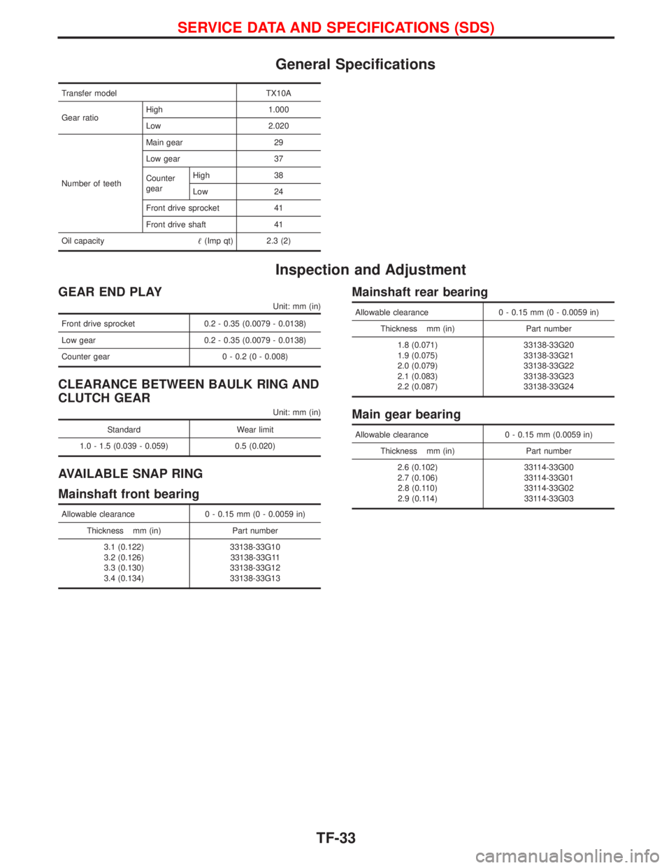
General Specifications
Transfer model TX10A
Gear ratioHigh 1.000
Low 2.020
Number of teethMain gear 29
Low gear 37
Counter
gearHigh 38
Low 24
Front drive sprocket 41
Front drive shaft 41
Oil capacity(Imp qt) 2.3 (2)
Inspection and Adjustment
GEAR END PLAY
Unit: mm (in)
Front drive sprocket 0.2 - 0.35 (0.0079 - 0.0138)
Low gear 0.2 - 0.35 (0.0079 - 0.0138)
Counter gear 0 - 0.2 (0 - 0.008)
CLEARANCE BETWEEN BAULK RING AND
CLUTCH GEAR
Unit: mm (in)
Standard Wear limit
1.0 - 1.5 (0.039 - 0.059) 0.5 (0.020)
AVAILABLE SNAP RING
Mainshaft front bearing
Allowable clearance 0 - 0.15 mm (0 - 0.0059 in)
Thickness mm (in) Part number
3.1 (0.122)
3.2 (0.126)
3.3 (0.130)
3.4 (0.134)33138-33G10
33138-33G11
33138-33G12
33138-33G13
Mainshaft rear bearing
Allowable clearance 0 - 0.15 mm (0 - 0.0059 in)
Thickness mm (in) Part number
1.8 (0.071)
1.9 (0.075)
2.0 (0.079)
2.1 (0.083)
2.2 (0.087)33138-33G20
33138-33G21
33138-33G22
33138-33G23
33138-33G24
Main gear bearing
Allowable clearance 0 - 0.15 mm (0.0059 in)
Thickness mm (in) Part number
2.6 (0.102)
2.7 (0.106)
2.8 (0.110)
2.9 (0.114)33114-33G00
33114-33G01
33114-33G02
33114-33G03
SERVICE DATA AND SPECIFICATIONS (SDS)
TF-33