Page 1495 of 1767
Checking Exhaust System
Check exhaust pipes, muffler and mounting for proper attachment,
leaks, cracks, damage, loose connections, chafing and deteriora-
tion. Replace all defective parts.
Checking Clutch Operation
Check clutch pedal height, free play and smooth operation.
Pedal height ªHº:
RHD:
210 - 220 mm (8.27 - 8.66 in)
LHD:
227 - 237 mm (8.94 - 9.33 in)
Pedal free play ªAº:
1.0 - 3.0 mm (0.039 - 0.118 in)
If necessary, adjust clutch pedal height and pedal free play. Refer
to Section CL.
Checking Clutch Fluid Level and Leaks
IIf fluid level is extremely low, check clutch system for leaks.
Checking Clutch System
Check fluid lines and operating cylinder for improper attachment,
cracks, damage, loose connections, chafing and deterioration.
Checking M/T Oil
1. Check for oil leakage.
SMA211A
SMA438A
SMA941B
SMA741A
SMA429A
CHASSIS AND BODY MAINTENANCE
MA-36
Page 1496 of 1767
2. Check oil level.
Never start engine while checking oil level.
Filler plug:
:25-34N×m (2.5 - 3.5 kg-m, 18 - 25 ft-lb)
Changing M/T Oil
Oil capacity:
3.5 liters (6-1/8 Imp pt)
Checking Water Entry
Check water entry in the clutch housing by removing the seal-
ing grommet, whenever driving in deep water or mud.
Checking Transfer Oil
1. Check transfer for leakage.
2. Check oil level.
Never start engine while checking oil level.
ªDEXRON
TMº type Automatic Transmission Fluid is used for
the transfer in the factory. Never add gear oil (API GL-4) to
Automatic Transmission Fluid.
SMA103
SMA255A
SMA369B
SMT483A
YMA009
CHASSIS AND BODY MAINTENANCE
Checking M/T Oil (Cont'd)
MA-37
Page 1508 of 1767
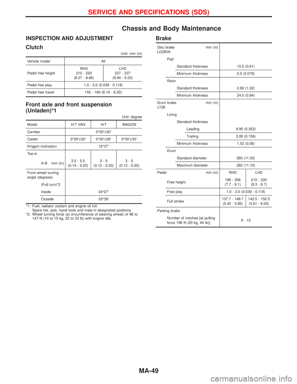
Chassis and Body Maintenance
INSPECTION AND ADJUSTMENT
Clutch
Unit: mm (in)
Vehicle model All
Pedal free heightRHD
210 - 220
(8.27 - 8.66)LHD
227 - 237
(8.94 - 9.33)
Pedal free play 1.0 - 3.0 (0.039 - 0.118)
Pedal free travel 155 - 160 (6.10 - 6.30)
Front axle and front suspension
(Unladen)*1
Unit: degree
Model H/T VAN H/T WAGON
Camber 0É30¢ 30¢
Caster 0É29¢ 30¢0É30¢ 30¢0É30¢ 30¢
Kingpin inclination 12É37¢
Toe-in
A-B mm (in)3.5 - 5.5
(0.14 - 0.22)3-5
(0.12 - 0.20)3-5
(0.12 - 0.20)
Front wheel turning
angle (degrees)
(Full turn)*2
Inside 34É27¢
Outside 33É38¢
*1: Fuel, radiator coolant and engine oil full.
Spare tire, jack, hand tools and mats in designated positions.
*2: Wheel turning force (at circumference of steering wheel) of 98 to
147 N (10 to 15 kg, 22 to 33 lb) with engine idle.
Brake
Disc brake mm (in)
LD28VA
Pad
Standard thickness 15.5 (0.61)
Minimum thickness 2.0 (0.079)
Rotor
Standard thickness 2.60 (1.02)
Minimum thickness 24.0 (0.94)
Drum brake mm (in)
LT28
Lining
Standard thickness
Leading 8.95 (0.352)
Trailing 3.95 (0.156)
Minimum thickness 1.52 (0.06)
Drum
Standard diameter 280 (11.02)
Maximum diameter 282 (11.10)
Pedal mm (in) RHD LHD
Free height196 - 206
(7.7 - 8.1)210 - 220
(8.3 - 8.7)
Free play 1.0 - 3.0 (0.039 - 0.118)
Full stroke137.7 - 148.7
(5.42 - 5.85)142.5 - 152.5
(5.61 - 6.00)
Parking brake
Number of notches [at pulling
force 196 N (20 kg, 44 lb)]9-10
SERVICE AND SPECIFICATIONS (SDS)
MA-49
Page 1509 of 1767
Wheel runout
Unit: mm (in)
Wheel typeSteel Aluminum
16²x7J 16²x7J
Radial runout limit 0.5 (0.020) 0.3 (0.012)
Lateral runout limit 0.8 (0.031) 0.3 (0.012)
Wheel bearing
Axial end play limit mm (in) 0
Lock nut
Tightening torque
N×m (kg-m, ft-lb)78-98
(7.9 - 10, 57 - 72)
Retightening torque
N×m (kg-m, in-lb)0.5 - 1.5
(0.05 - 0.15,4-13)
TIGHTENING TORQUE
Unit N×m kg-m ft-lb
Clutch
Pedal stopper lock nut 12 - 15 1.2 - 1.5 8.7 - 10.8
Master cylinder push rod
lock nut8 - 11 0.8 - 1.1 5.8 - 8.0
Manual transmission
Drain and filler plugs
FS5R30A 25 - 34 2.5 - 3.5 18 - 25
Differential carrier
Drain and filler plugs
R180A 39 - 59 4 - 6 28.8 - 43.5
H233B 59 - 98 6 - 10 43.5 - 72.3
Front axle and front suspen-
sion
Tie-rod lock nut 60 - 70 6.1 - 7.1 44.3 - 51.6
Brake system
Air bleeder valve 7 - 9 0.7 - 0.9 5.1 - 6.5
Wheel and tire
Wheel nut 118 - 147 12.0 - 15.087.0 -
108.4
SERVICE AND SPECIFICATIONS (SDS)
Chassis and Body Maintenance (Cont'd)
MA-50
Page 1516 of 1767
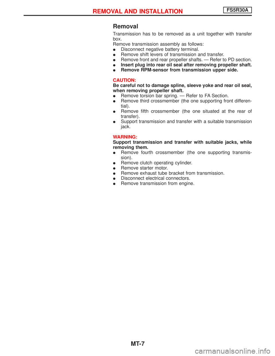
Removal
Transmission has to be removed as a unit together with transfer
box.
Remove transmission assembly as follows:
IDisconnect negative battery terminal.
IRemove shift levers of transmission and transfer.
IRemove front and rear propeller shafts. Ð Refer to PD section.
IInsert plug into rear oil seal after removing propeller shaft.
IRemove RPM-sensor from transmission upper side.
CAUTION:
Be careful not to damage spline, sleeve yoke and rear oil seal,
when removing propeller shaft.
IRemove torsion bar spring. Ð Refer to FA Section.
IRemove third crossmember (the one supporting front differen-
tial).
IRemove fifth crossmember (the one situated at the rear of
transfer).
ISupport transmission and transfer with a suitable transmission
jack.
WARNING:
Support transmission and transfer with suitable jacks, while
removing them.
IRemove fourth crossmember (the one supporting transmis-
sion).
IRemove clutch operating cylinder.
IRemove starter motor.
IRemove exhaust tube bracket from transmission.
IDisconnect electrical connectors.
IRemove transmission from engine.
REMOVAL AND INSTALLATIONFS5R30A
MT-7
Page 1518 of 1767
IRaise the unit with a hoist.
IPosition the transmission assembly on a portable jack and
secure it with a suitable tool.
Lift the assembly until the gearbox input shaft faces its hous-
ing.
Move the assembly towards the engine. The assembly must be
rotated slightly so that the starter motor housing clears the
projection on the companion floor. Insert input shaft into its
housing (slightly raising the rear of the transfer box may facili-
tate the introduction of the shaft into its housing).
ITighten the screws securing the gearbox to the engine.
:39-49N×m (4.0 - 5.0 kg-m, 29 - 36 ft-lb)
IConnect the electrical wiring. Secure with the respective clips.
IFit the RPM-sensor to the transmission upper side.
IFit the exhaust pipe support bracket to the transfer box.
:13-16N×m (1.3 - 1.6 kg-m,9-12ft-lb)
IFit the starter motor. Secure the earth wire to the starter motor
lower screw.
:31-41N×m (3.2 - 4.2 kg-m, 23 - 30 ft-lb)
IFit the clutch slave cylinder.
:30-40N×m (3.1 - 4.1 kg-m, 22 - 30 ft-lb)
IInstall fourth crossmember (Note the ªfrontº mark).
Crossmember fixing bolts to chassis:
:41-52N×m (4.2 - 5.3 kg-m, 30 - 38 ft-lb)
Crossmember fixing bolts to transmission:
:68-87N×m (6.9 - 8.9 kg-m, 50 - 64 ft-lb)
ITake away the portable jack holding boxes assembly.
IInstall fifth crossmember.
:59-78N×m (6.0 - 8.0 kg-m, 43 - 58 ft-lb)
IInstall third crossmember.
: Screws: 41 - 52 N×m (4.2 - 5.3 kg-m,
30 - 38 ft-lb)
Nuts: 68 - 87 N×m (6.9 - 8.9 kg-m,
50 - 64 ft-lb)
IInstall torsion bar springs. Ð Refer to FA section.
IInstall front and rear propeller shafts. Ð Refer to PD section.
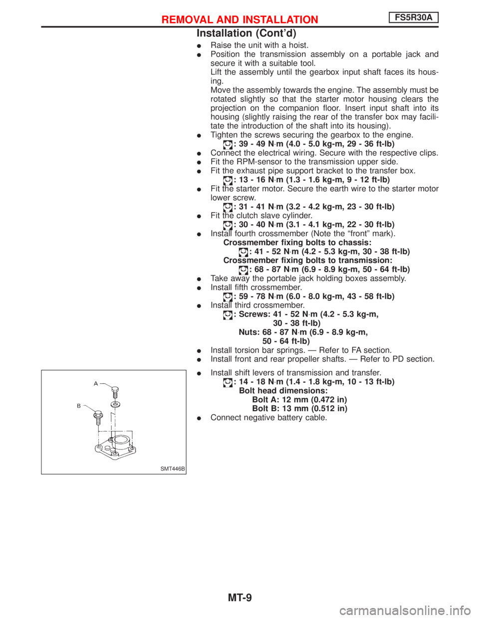
IInstall shift levers of transmission and transfer.
:14-18N×m (1.4 - 1.8 kg-m, 10 - 13 ft-lb)
Bolt head dimensions:
Bolt A: 12 mm (0.472 in)
Bolt B: 13 mm (0.512 in)
IConnect negative battery cable.
SMT446B
REMOVAL AND INSTALLATIONFS5R30A
Installation (Cont'd)
MT-9
Page 1589 of 1767
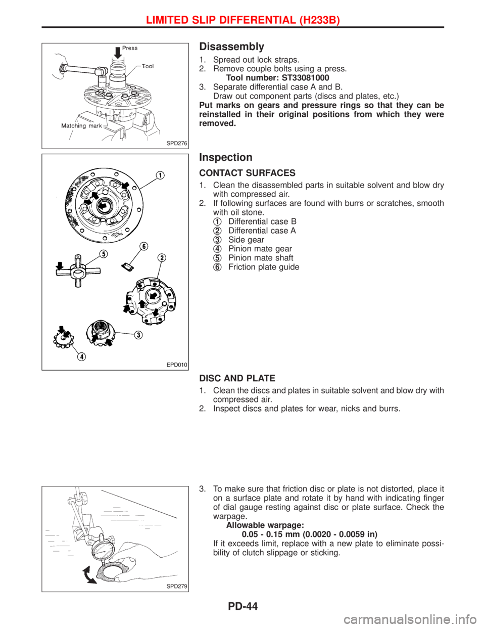
Disassembly
1. Spread out lock straps.
2. Remove couple bolts using a press.
Tool number: ST33081000
3. Separate differential case A and B.
Draw out component parts (discs and plates, etc.)
Put marks on gears and pressure rings so that they can be
reinstalled in their original positions from which they were
removed.
Inspection
CONTACT SURFACES
1. Clean the disassembled parts in suitable solvent and blow dry
with compressed air.
2. If following surfaces are found with burrs or scratches, smooth
with oil stone.
q
1Differential case B
q
2Differential case A
q
3Side gear
q
4Pinion mate gear
q
5Pinion mate shaft
q
6Friction plate guide
DISC AND PLATE
1. Clean the discs and plates in suitable solvent and blow dry with
compressed air.
2. Inspect discs and plates for wear, nicks and burrs.
3. To make sure that friction disc or plate is not distorted, place it
on a surface plate and rotate it by hand with indicating finger
of dial gauge resting against disc or plate surface. Check the
warpage.
Allowable warpage:
0.05 - 0.15 mm (0.0020 - 0.0059 in)
If it exceeds limit, replace with a new plate to eliminate possi-
bility of clutch slippage or sticking.
SPD276
EPD010
SPD279
LIMITED SLIP DIFFERENTIAL (H233B)
PD-44
Page 1682 of 1767
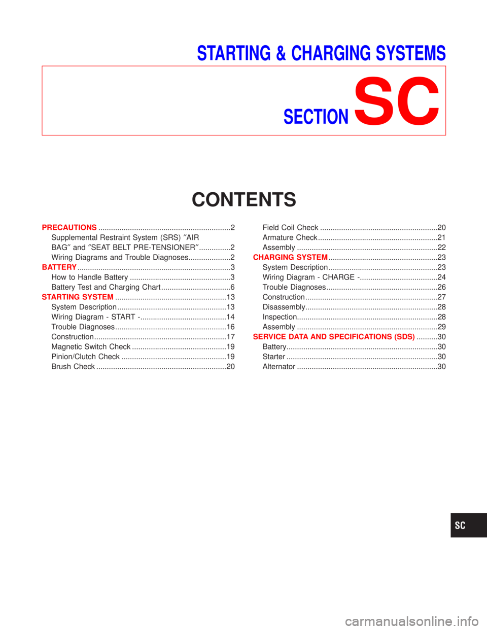
STARTING & CHARGING SYSTEMS
SECTION
SC
CONTENTS
PRECAUTIONS...............................................................2
Supplemental Restraint System (SRS)²AIR
BAG²and²SEAT BELT PRE-TENSIONER²...............2
Wiring Diagrams and Trouble Diagnoses....................2
BATTERY.........................................................................3
How to Handle Battery ................................................3
Battery Test and Charging Chart .................................6
STARTING SYSTEM.....................................................13
System Description ....................................................13
Wiring Diagram - START -.........................................14
Trouble Diagnoses.....................................................16
Construction ...............................................................17
Magnetic Switch Check .............................................19
Pinion/Clutch Check ..................................................19
Brush Check ..............................................................20Field Coil Check ........................................................20
Armature Check .........................................................21
Assembly ...................................................................22
CHARGING SYSTEM....................................................23
System Description ....................................................23
Wiring Diagram - CHARGE -.....................................24
Trouble Diagnoses.....................................................26
Construction ...............................................................27
Disassembly...............................................................28
Inspection...................................................................28
Assembly ...................................................................29
SERVICE DATA AND SPECIFICATIONS (SDS)..........30
Battery........................................................................30
Starter ........................................................................30
Alternator ...................................................................30