Page 1352 of 1767

***: Not applicable
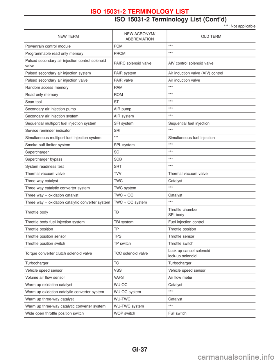
NEW TERMNEW ACRONYM/
ABBREVIATIONOLD TERM
Powertrain control module PCM ***
Programmable read only memory PROM ***
Pulsed secondary air injection control solenoid
valvePAIRC solenoid valve AIV control solenoid valve
Pulsed secondary air injection system PAIR system Air induction valve (AIV) control
Pulsed secondary air injection valve PAIR valve Air induction valve
Random access memory RAM ***
Read only memory ROM ***
Scan tool ST ***
Secondary air injection pump AIR pump ***
Secondary air injection system AIR system ***
Sequential multiport fuel injection system SFI system Sequential fuel injection
Service reminder indicator SRI ***
Simultaneous multiport fuel injection system *** Simultaneous fuel injection
Smoke puff limiter system SPL system ***
Supercharger SC ***
Supercharger bypass SCB ***
System readiness test SRT ***
Thermal vacuum valve TVV Thermal vacuum valve
Three way catalyst TWC Catalyst
Three way catalytic converter system TWC system ***
Three way + oxidation catalyst TWC + OC Catalyst
Three way + oxidation catalytic converter system TWC + OC system ***
Throttle body TBThrottle chamber
SPI body
Throttle body fuel injection system TBI system Fuel injection control
Throttle position TP Throttle position
Throttle position sensor TPS Throttle sensor
Throttle position switch TP switch Throttle switch
Torque converter clutch solenoid valve TCC solenoid valveLock-up cancel solenoid
lock-up solenoid
Turbocharger TC Turbocharger
Vehicle speed sensor VSS Vehicle speed sensor
Volume air flow sensor VAFS Air flow meter
Warm up oxidation catalyst WU-OC Catalyst
Warm up oxidation catalytic converter system WU-OC system ***
Warm up three-way catalyst WU-TWC Catalyst
Warm up three-way catalytic converter system WU-TWC system ***
Wide open throttle position switch WOP switch Full switch
ISO 15031-2 TERMINOLOGY LIST
ISO 15031-2 Terminology List (Cont'd)
GI-37
Page 1354 of 1767

HEATER & AIR CONDITIONER
SECTION
HA
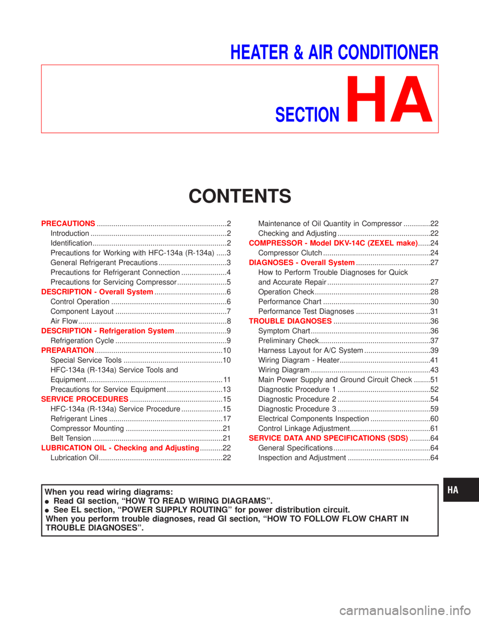
CONTENTS
PRECAUTIONS...............................................................2
Introduction ..................................................................2
Identification .................................................................2
Precautions for Working with HFC-134a (R-134a) .....3
General Refrigerant Precautions .................................3
Precautions for Refrigerant Connection ......................4
Precautions for Servicing Compressor ........................5
DESCRIPTION - Overall System...................................6
Control Operation ........................................................6
Component Layout ......................................................7
Air Flow ........................................................................8
DESCRIPTION - Refrigeration System.........................9
Refrigeration Cycle ......................................................9
PREPARATION..............................................................10
Special Service Tools ................................................10
HFC-134a (R-134a) Service Tools and
Equipment .................................................................. 11
Precautions for Service Equipment ...........................13
SERVICE PROCEDURES.............................................15
HFC-134a (R-134a) Service Procedure ....................15
Refrigerant Lines .......................................................17
Compressor Mounting ...............................................21
Belt Tension ...............................................................21
LUBRICATION OIL - Checking and Adjusting...........22
Lubrication Oil ............................................................22Maintenance of Oil Quantity in Compressor .............22
Checking and Adjusting .............................................22
COMPRESSOR - Model DKV-14C (ZEXEL make)......24
Compressor Clutch ....................................................24
DIAGNOSES - Overall System....................................27
How to Perform Trouble Diagnoses for Quick
and Accurate Repair ..................................................27
Operation Check ........................................................28
Performance Chart ....................................................30
Performance Test Diagnoses ....................................31
TROUBLE DIAGNOSES...............................................36
Symptom Chart ..........................................................36
Preliminary Check......................................................37
Harness Layout for A/C System ................................39
Wiring Diagram - Heater............................................41
Wiring Diagram ..........................................................43
Main Power Supply and Ground Circuit Check ........51
Diagnostic Procedure 1 .............................................52
Diagnostic Procedure 2 .............................................54
Diagnostic Procedure 3 .............................................59
Electrical Components Inspection .............................60
Control Linkage Adjustment.......................................61
SERVICE DATA AND SPECIFICATIONS (SDS)..........64
General Specifications ...............................................64
Inspection and Adjustment ........................................64
When you read wiring diagrams:
IRead GI section, ªHOW TO READ WIRING DIAGRAMSº.
ISee EL section, ªPOWER SUPPLY ROUTINGº for power distribution circuit.
When you perform trouble diagnoses, read GI section, ªHOW TO FOLLOW FLOW CHART IN
TROUBLE DIAGNOSESº.
Page 1358 of 1767

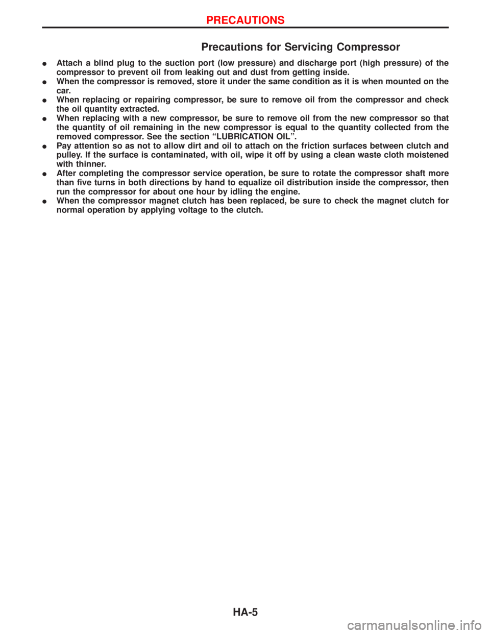
Precautions for Servicing Compressor
IAttach a blind plug to the suction port (low pressure) and discharge port (high pressure) of the
compressor to prevent oil from leaking out and dust from getting inside.
IWhen the compressor is removed, store it under the same condition as it is when mounted on the
car.
IWhen replacing or repairing compressor, be sure to remove oil from the compressor and check
the oil quantity extracted.
IWhen replacing with a new compressor, be sure to remove oil from the new compressor so that
the quantity of oil remaining in the new compressor is equal to the quantity collected from the
removed compressor. See the section ªLUBRICATION OILº.
IPay attention so as not to allow dirt and oil to attach on the friction surfaces between clutch and
pulley. If the surface is contaminated, with oil, wipe it off by using a clean waste cloth moistened
with thinner.
IAfter completing the compressor service operation, be sure to rotate the compressor shaft more
than five turns in both directions by hand to equalize oil distribution inside the compressor, then
run the compressor for about one hour by idling the engine.
IWhen the compressor magnet clutch has been replaced, be sure to check the magnet clutch for
normal operation by applying voltage to the clutch.
PRECAUTIONS
HA-5
Page 1363 of 1767
Special Service Tools
Tool number
Tool nameDescription
KV99231260
Clutch disc wrench
Removing shaft nut and clutch disc
KV99232340
Clutch disc puller
Removing clutch disc
KV99234330
Pulley installer
Installing pulley
KV99233130
Pulley puller
Removing pulley
PREPARATION
HA-10
Page 1377 of 1767
Compressor Clutch
REMOVAL
IWhen removing center bolt, hold clutch disc with clutch disc
wrench.
IRemove the drive plate using the drive plate puller.
Insert the holder's three pins into the holes in the drive plate,
and rotate the holder clockwise to hook it onto the plate. Then,
tighten the center bolt to remove the drive plate.
When tightening the center bolt, insert a round bar (screwdriver,
etc.) between two of the pins (as shown in the left-hand figure)
to prevent drive plate rotation. After removing the drive plate,
remove the shims from either the drive shaft or the drive plate.
YHA403
RHA070C
RHA071C
COMPRESSOR Ð Model DKV-14C (ZEXEL make)
HA-24
Page 1378 of 1767

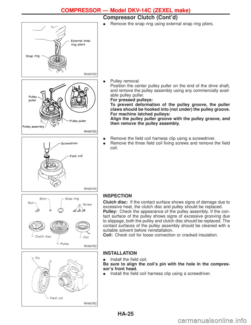
IRemove the snap ring using external snap ring pliers.
IPulley removal
Position the center pulley puller on the end of the drive shaft,
and remove the pulley assembly using any commercially avail-
able pulley puller.
For pressed pulleys:
To prevent deformation of the pulley groove, the puller
claws should be hooked into (not under) the pulley groove.
For machine latched pulleys:
Align the pulley puller groove with the pulley groove, and
then remove the pulley assembly.
IRemove the field coil harness clip using a screwdriver.
IRemove the three field coil fixing screws and remove the field
coil.
INSPECTION
Clutch disc:If the contact surface shows signs of damage due to
excessive heat, the clutch disc and pulley should be replaced.
Pulley:Check the appearance of the pulley assembly. If the con-
tact surface of the pulley shows signs of excessive grooving due
to slippage, both the pulley and clutch disc should be replaced. The
contact surfaces of the pulley assembly should be cleaned with a
suitable solvent before reinstallation.
Coil:Check coil for loose connection or cracked insulation.
INSTALLATION
IInstall the field coil.
Be sure to align the coil's pin with the hole in the compres-
sor's front head.
IInstall the field coil harness clip using a screwdriver.
RHA072C
RHA073C
RHA074C
RHA075C
RHA076C
COMPRESSOR Ð Model DKV-14C (ZEXEL make)
Compressor Clutch (Cont'd)
HA-25
Page 1379 of 1767
IInstall the pulley assembly using the installer and a hand press,
and then install the snap ring using snap ring pliers.
IInstall the drive plate on the drive shaft, together with the origi-
nal shim(s). Press the drive plate down by hand.
IUsing the holder to prevent drive plate rotation, tighten the bolt
to 12 to 15 N×m (1.2 to 1.5 kg-m, 9 to 11 ft-lb) torque.
After tightening the bolt, check that the pulley rotates
smoothly.
ICheck clearance around the entire periphery of clutch disc.
Disc-to-pulley clearance:
0.3 - 0.6 mm (0.012 - 0.024 in)
If the specified clearance is not obtained, replace adjusting
spacer and readjust.
BREAK-IN OPERATION
When replacing compressor clutch assembly, do not forget break-in
operation, accomplished by engaging and disengaging the clutch
about thirty times. Break-in operation raises the level of transmit-
ted torque.
RHA077C
RHA078C
RHA079C
RHA080C
COMPRESSOR Ð Model DKV-14C (ZEXEL make)
Compressor Clutch (Cont'd)
HA-26
Page 1389 of 1767
Symptom Chart
DIAGNOSTIC TABLE
PROCEDUREPrelimi-
nary
CheckDiagnostic
ProcedureMain Power
Supply and
Ground Circuit
CheckElectrical Components Inspection
SYMPTOM
Preliminary check 1
Preliminary check 2
Diagnostic procedure 1
Diagnostic procedure 2
Diagnostic procedure 3
15A Fuses
10A Fuse
15A Fuse
Blower motor
Intake door motor
Resistor
A/C switch
Fan switch
A/C relay
Dual-pressure switch
Compressor
Harness Magnet clutch
A/C does not blow cold air.q qqqq qqqqqqq
Blower motor does not rotate.
qqqqq q
Magnet clutch does not
engage when A/C switch and
fan switch are ON.
qq qqqqqq
Noise
Intake door does not change.qq q
,: The number indicates checking order.
q: Refer to each flow chart for checking order. (It depends on malfunctioning portion.)
TROUBLE DIAGNOSES
HA-36