Page 194 of 1767
e. Install control valve assembly on transmission case.
f. Install connector tube brackets and tighten boltsq
AandqB.
ICheck that terminal assembly does not catch.
Bolt symbolmm (in)
qA33 (1.30)
q
B45 (1.77)
g. Install O-ring on oil strainer.
IApply petroleum jelly to O-ring.
h. Install oil strainer on control valve.
i. Securely fasten terminal harness with clips.
j. Install torque converter clutch solenoid valve and fluid tempera-
ture sensor connectors.
SAT353B
SAT221B
SAT009B
SAT010B
ASSEMBLY
Assembly (2) (Cont'd)
AT-192
Page 199 of 1767
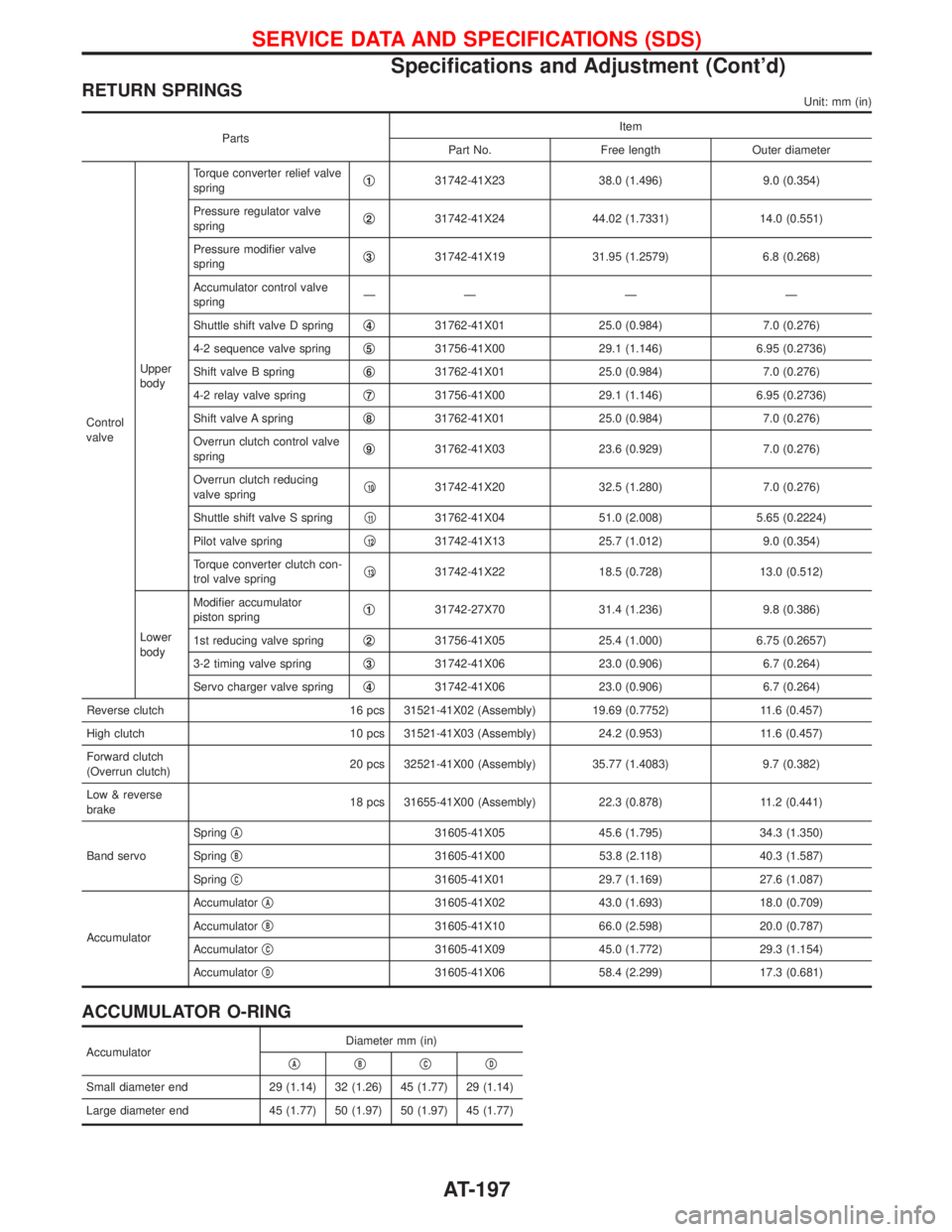
RETURN SPRINGSUnit: mm (in)
PartsItem
Part No. Free length Outer diameter
Control
valveUpper
bodyTorque converter relief valve
springq
131742-41X23 38.0 (1.496) 9.0 (0.354)
Pressure regulator valve
springq
231742-41X24 44.02 (1.7331) 14.0 (0.551)
Pressure modifier valve
springq
331742-41X19 31.95 (1.2579) 6.8 (0.268)
Accumulator control valve
springÐÐÐÐ
Shuttle shift valve D springq
431762-41X01 25.0 (0.984) 7.0 (0.276)
4-2 sequence valve springq
531756-41X00 29.1 (1.146) 6.95 (0.2736)
Shift valve B springq
631762-41X01 25.0 (0.984) 7.0 (0.276)
4-2 relay valve springq
731756-41X00 29.1 (1.146) 6.95 (0.2736)
Shift valve A springq
831762-41X01 25.0 (0.984) 7.0 (0.276)
Overrun clutch control valve
springq
931762-41X03 23.6 (0.929) 7.0 (0.276)
Overrun clutch reducing
valve springq
1031742-41X20 32.5 (1.280) 7.0 (0.276)
Shuttle shift valve S springq
1131762-41X04 51.0 (2.008) 5.65 (0.2224)
Pilot valve springq
1231742-41X13 25.7 (1.012) 9.0 (0.354)
Torque converter clutch con-
trol valve springq
1331742-41X22 18.5 (0.728) 13.0 (0.512)
Lower
bodyModifier accumulator
piston springq
131742-27X70 31.4 (1.236) 9.8 (0.386)
1st reducing valve springq
231756-41X05 25.4 (1.000) 6.75 (0.2657)
3-2 timing valve springq
331742-41X06 23.0 (0.906) 6.7 (0.264)
Servo charger valve springq
431742-41X06 23.0 (0.906) 6.7 (0.264)
Reverse clutch 16 pcs 31521-41X02 (Assembly) 19.69 (0.7752) 11.6 (0.457)
High clutch 10 pcs 31521-41X03 (Assembly) 24.2 (0.953) 11.6 (0.457)
Forward clutch
(Overrun clutch)20 pcs 32521-41X00 (Assembly) 35.77 (1.4083) 9.7 (0.382)
Low & reverse
brake18 pcs 31655-41X00 (Assembly) 22.3 (0.878) 11.2 (0.441)
Band servoSpringq
A31605-41X05 45.6 (1.795) 34.3 (1.350)
Springq
B31605-41X00 53.8 (2.118) 40.3 (1.587)
Springq
C31605-41X01 29.7 (1.169) 27.6 (1.087)
AccumulatorAccumulatorq
A31605-41X02 43.0 (1.693) 18.0 (0.709)
Accumulatorq
B31605-41X10 66.0 (2.598) 20.0 (0.787)
Accumulatorq
C31605-41X09 45.0 (1.772) 29.3 (1.154)
Accumulatorq
D31605-41X06 58.4 (2.299) 17.3 (0.681)
ACCUMULATOR O-RING
AccumulatorDiameter mm (in)
qAqBqCqD
Small diameter end 29 (1.14) 32 (1.26) 45 (1.77) 29 (1.14)
Large diameter end 45 (1.77) 50 (1.97) 50 (1.97) 45 (1.77)
SERVICE DATA AND SPECIFICATIONS (SDS)
Specifications and Adjustment (Cont'd)
AT-197
Page 200 of 1767
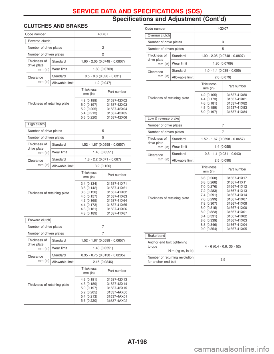
CLUTCHES AND BRAKES
Code number 4GX07
Reverse clutch
Number of drive plates 2
Number of driven plates 2
Thickness of
drive plate
mm (in)Standard 1.90 - 2.05 (0.0748 - 0.0807)
Wear limit 1.80 (0.0709)
Clearance
mm (in)Standard 0.5 - 0.8 (0.020 - 0.031)
Allowable limit 1.2 (0.047)
Thickness of retaining plateThickness
mm (in)Part number
4.8 (0.189)
5.0 (0.197)
5.2 (0.205)
5.4 (0.213)
5.6 (0.220)31537-42X02
31537-42X03
31537-42X04
31537-42X05
31537-42X06
High clutch
Number of drive plates 5
Number of driven plates 5
Thickness of
drive plate
mm (in)Standard 1.52 - 1.67 (0.0598 - 0.0657)
Wear limit 1.40 (0.0551)
Clearance
mm (in)Standard 1.8 - 2.2 (0.071 - 0.087)
Allowable limit 3.2 (0.126)
Thickness of retaining plateThickness
mm (in)Part number
3.4 (0.134)
3.6 (0.142)
3.8 (0.150)
4.0 (0.157)
4.2 (0.165)
4.4 (0.173)
4.6 (0.181)
4.8 (0.189)31537-41X71
31537-41X61
31537-41X62
31537-41X63
31537-41X64
31537-41X65
31537-41X66
31537-41X67
Forward clutch
Number of drive plates 7
Number of driven plates 7
Thickness of
drive plate
mm (in)Standard 1.52 - 1.67 (0.0598 - 0.0657)
Wear limit 1.40 (0.0551)
Clearance
mm (in)Standard 0.35 - 0.75 (0.0138 - 0.0295)
Allowable limit 2.15 (0.0846)
Thickness of retaining plateThickness
mm (in)Part number
4.6 (0.181)
4.8 (0.189)
5.0 (0.197)
5.2 (0.205)
5.4 (0.213)
5.6 (0.220)31537-42X13
31537-42X14
31537-42X15
31537-4AX00
31537-4AX01
31537-4AX02
Code number 4GX07
Overrun clutch
Number of drive plates 3
Number of driven plates 5
Thickness of
drive plate
mm (in)Standard 1.90 - 2.05 (0.0748 - 0.0807)
Wear limit 1.80 (0.0709)
Clearance
mm (in)Standard 1.0 - 1.4 (0.039 - 0.055)
Allowable limit 2.0 (0.079)
Thickness of retaining plateThickness
mm (in)Part number
4.2 (0.165)
4.4 (0.173)
4.6 (0.181)
4.8 (0.189)
5.0 (0.197)31537-41X80
31537-41X81
31537-41X82
31537-41X83
31537-41X84
Low & reverse brake
Number of drive plates 7
Number of driven plates 7
Thickness of
drive plate
mm (in)Standard 1.52 - 1.67 (0.0598 - 0.0657)
Wear limit 1.4 (0.055)
Clearance
mm (in)Standard 0.8 - 1.1 (0.031 - 0.043)
Allowable limit 2.5 (0.098)
Thickness of retaining plateThickness
mm (in)Part number
6.6 (0.260)
6.8 (0.268)
7.0 (0.276)
7.2 (0.283)
7.4 (0.291)
7.6 (0.299)
7.8 (0.307)
8.0 (0.315)
8.2 (0.323)
8.4 (0.331)
8.6 (0.339)
8.8 (0.346)
9.0 (0.354)31667-41X17
31667-41X11
31667-41X12
31667-41X13
31667-41X14
31667-41X07
31667-41X08
31667-41X00
31667-41X01
31667-41X02
31667-41X03
31667-41X04
31667-41X05
Brake band
Anchor end bolt tightening
torque
N×m (kg-m, in-lb)4 - 6 (0.4 - 0.6, 35 - 52)
Number of returning revolution
for anchor end bolt2.5
SERVICE DATA AND SPECIFICATIONS (SDS)
Specifications and Adjustment (Cont'd)
AT-198
Page 201 of 1767
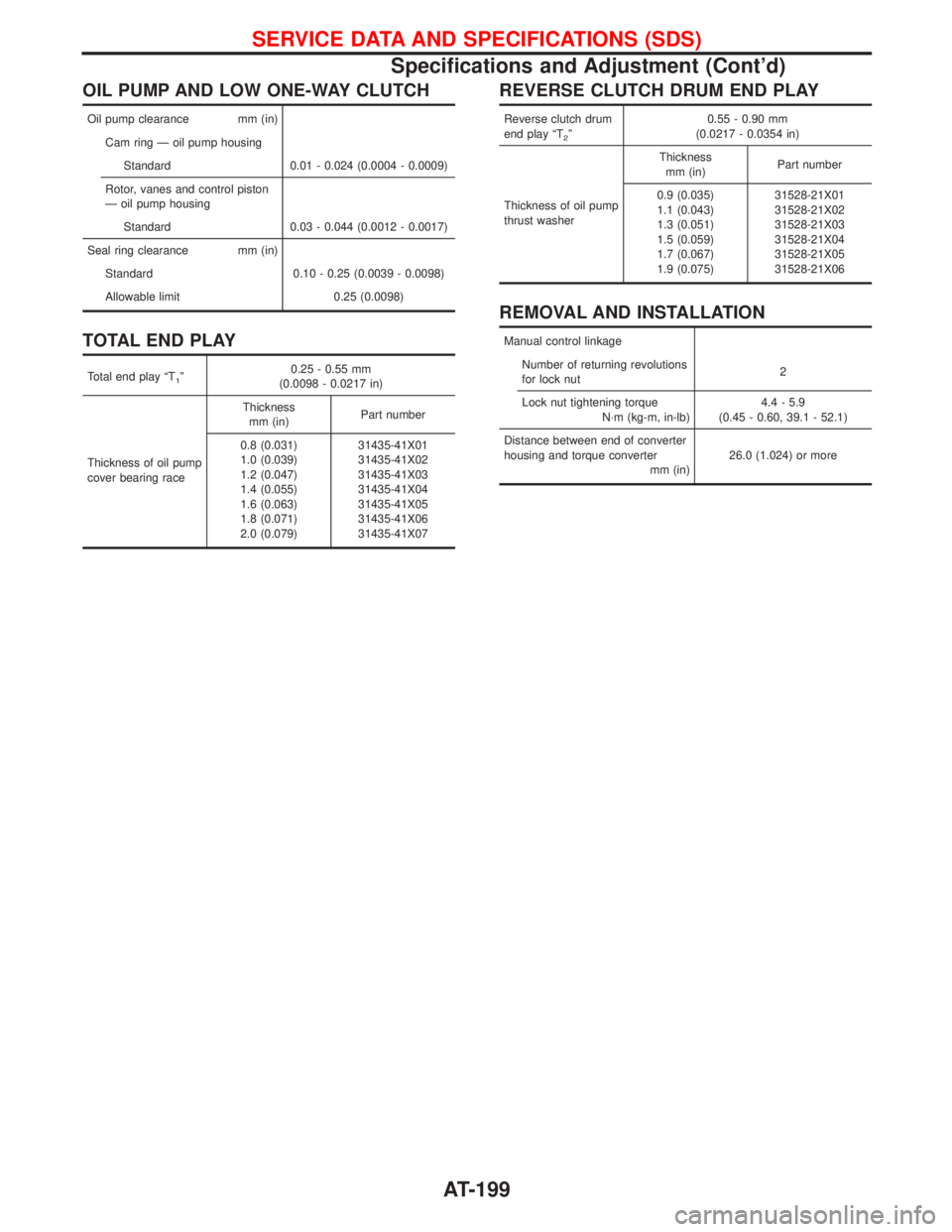
OIL PUMP AND LOW ONE-WAY CLUTCH
Oil pump clearance mm (in)
Cam ring Ð oil pump housing
Standard 0.01 - 0.024 (0.0004 - 0.0009)
Rotor, vanes and control piston
Ð oil pump housing
Standard 0.03 - 0.044 (0.0012 - 0.0017)
Seal ring clearance mm (in)
Standard 0.10 - 0.25 (0.0039 - 0.0098)
Allowable limit 0.25 (0.0098)
TOTAL END PLAY
Total end play ªT1º0.25 - 0.55 mm
(0.0098 - 0.0217 in)
Thickness of oil pump
cover bearing raceThickness
mm (in)Part number
0.8 (0.031)
1.0 (0.039)
1.2 (0.047)
1.4 (0.055)
1.6 (0.063)
1.8 (0.071)
2.0 (0.079)31435-41X01
31435-41X02
31435-41X03
31435-41X04
31435-41X05
31435-41X06
31435-41X07
REVERSE CLUTCH DRUM END PLAY
Reverse clutch drum
end play ªT
2º0.55 - 0.90 mm
(0.0217 - 0.0354 in)
Thickness of oil pump
thrust washerThickness
mm (in)Part number
0.9 (0.035)
1.1 (0.043)
1.3 (0.051)
1.5 (0.059)
1.7 (0.067)
1.9 (0.075)31528-21X01
31528-21X02
31528-21X03
31528-21X04
31528-21X05
31528-21X06
REMOVAL AND INSTALLATION
Manual control linkage
Number of returning revolutions
for lock nut2
Lock nut tightening torque
N×m (kg-m, in-lb)4.4 - 5.9
(0.45 - 0.60, 39.1 - 52.1)
Distance between end of converter
housing and torque converter
mm (in)26.0 (1.024) or more
SERVICE DATA AND SPECIFICATIONS (SDS)
Specifications and Adjustment (Cont'd)
AT-199
Page 349 of 1767
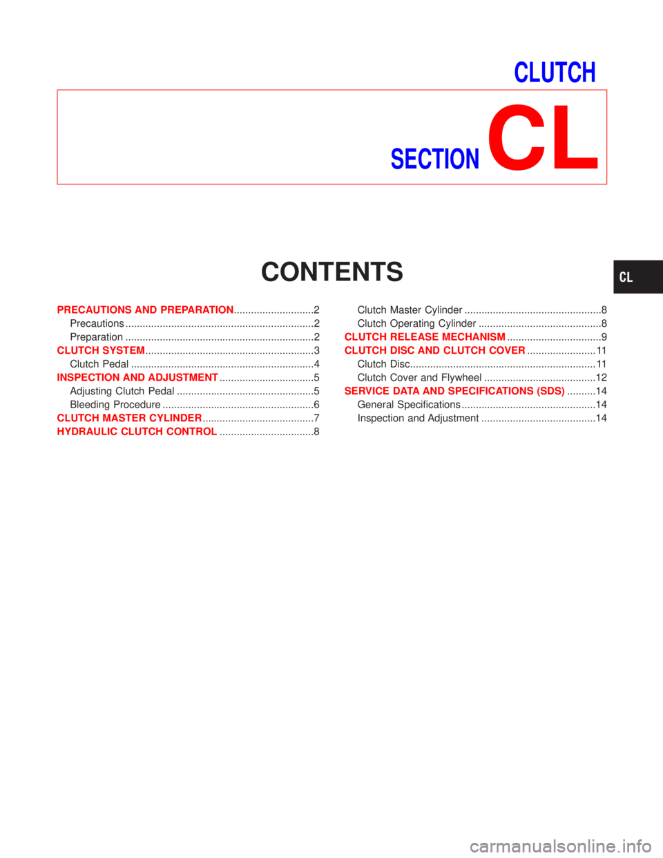
CLUTCH
SECTION
CL
CONTENTS
PRECAUTIONS AND PREPARATION............................2
Precautions ..................................................................2
Preparation ..................................................................2
CLUTCH SYSTEM...........................................................3
Clutch Pedal ................................................................4
INSPECTION AND ADJUSTMENT.................................5
Adjusting Clutch Pedal ................................................5
Bleeding Procedure .....................................................6
CLUTCH MASTER CYLINDER.......................................7
HYDRAULIC CLUTCH CONTROL.................................8Clutch Master Cylinder ................................................8
Clutch Operating Cylinder ...........................................8
CLUTCH RELEASE MECHANISM.................................9
CLUTCH DISC AND CLUTCH COVER........................ 11
Clutch Disc................................................................. 11
Clutch Cover and Flywheel .......................................12
SERVICE DATA AND SPECIFICATIONS (SDS)..........14
General Specifications ...............................................14
Inspection and Adjustment ........................................14
Page 350 of 1767
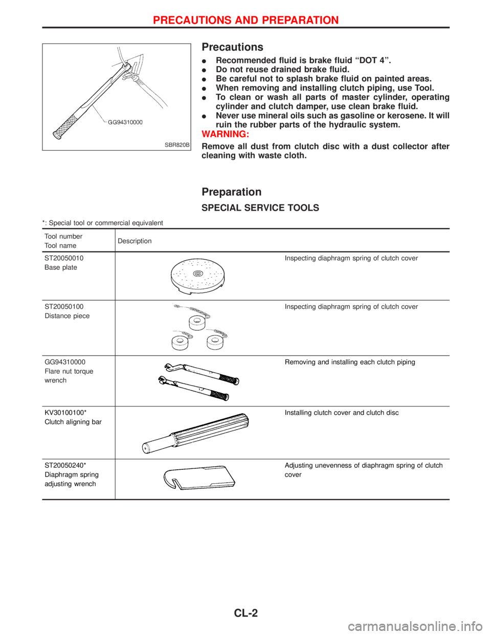
Precautions
IRecommended fluid is brake fluid ªDOT 4º.
IDo not reuse drained brake fluid.
IBe careful not to splash brake fluid on painted areas.
IWhen removing and installing clutch piping, use Tool.
ITo clean or wash all parts of master cylinder, operating
cylinder and clutch damper, use clean brake fluid.
INever use mineral oils such as gasoline or kerosene. It will
ruin the rubber parts of the hydraulic system.
WARNING:
Remove all dust from clutch disc with a dust collector after
cleaning with waste cloth.
Preparation
SPECIAL SERVICE TOOLS
*: Special tool or commercial equivalent
Tool number
Tool nameDescription
ST20050010
Base plate
Inspecting diaphragm spring of clutch cover
ST20050100
Distance piece
Inspecting diaphragm spring of clutch cover
GG94310000
Flare nut torque
wrench
Removing and installing each clutch piping
KV30100100*
Clutch aligning bar
Installing clutch cover and clutch disc
ST20050240*
Diaphragm spring
adjusting wrench
Adjusting unevenness of diaphragm spring of clutch
cover
SBR820B
PRECAUTIONS AND PREPARATION
CL-2
Page 351 of 1767
YCL022
CLUTCH SYSTEM
CL-3
Page 352 of 1767
Clutch Pedal
NCL045
CLUTCH SYSTEM
CL-4