2002 NISSAN TERRANO clutch
[x] Cancel search: clutchPage 16 of 1767
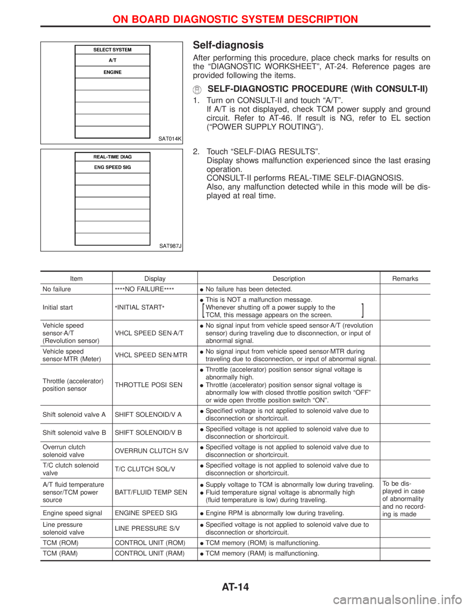
Self-diagnosis
After performing this procedure, place check marks for results on
the ªDIAGNOSTIC WORKSHEETº, AT-24. Reference pages are
provided following the items.
SELF-DIAGNOSTIC PROCEDURE (With CONSULT-II)
1. Turn on CONSULT-II and touch ªA/Tº.
If A/T is not displayed, check TCM power supply and ground
circuit. Refer to AT-46. If result is NG, refer to EL section
(ªPOWER SUPPLY ROUTINGº).
2. Touch ªSELF-DIAG RESULTSº.
Display shows malfunction experienced since the last erasing
operation.
CONSULT-II performs REAL-TIME SELF-DIAGNOSIS.
Also, any malfunction detected while in this mode will be dis-
played at real time.
Item Display Description Remarks
No failure
****NO FAILURE
****INo failure has been detected.
Initial start
*INITIAL START
*IThis is NOT a malfunction message.
Whenever shutting off a power supply to the
TCM, this message appears on the screen.
[]
Vehicle speed
sensor×A/T
(Revolution sensor)VHCL SPEED SEN×A/TINo signal input from vehicle speed sensor×A/T (revolution
sensor) during traveling due to disconnection, or input of
abnormal signal.
Vehicle speed
sensor×MTR (Meter)VHCL SPEED SEN×MTRINo signal input from vehicle speed sensor×MTR during
traveling due to disconnection, or input of abnormal signal.
Throttle (accelerator)
position sensorTHROTTLE POSI SENIThrottle (accelerator) position sensor signal voltage is
abnormally high.
IThrottle (accelerator) position sensor signal voltage is
abnormally low with closed throttle position switch ªOFFº
or wide open throttle position switch ªONº.
Shift solenoid valve A SHIFT SOLENOID/V AISpecified voltage is not applied to solenoid valve due to
disconnection or shortcircuit.
Shift solenoid valve B SHIFT SOLENOID/V BISpecified voltage is not applied to solenoid valve due to
disconnection or shortcircuit.
Overrun clutch
solenoid valveOVERRUN CLUTCH S/VISpecified voltage is not applied to solenoid valve due to
disconnection or shortcircuit.
T/C clutch solenoid
valveT/C CLUTCH SOL/VISpecified voltage is not applied to solenoid valve due to
disconnection or shortcircuit.
A/T fluid temperature
sensor/TCM power
sourceBATT/FLUID TEMP SENISupply voltage to TCM is abnormally low during traveling.
IFluid temperature signal voltage is abnormally high
(fluid temperature is low) during traveling.To be dis-
played in case
of abnormality
and no record-
ing is made Engine speed signal ENGINE SPEED SIGIEngine RPM is abnormally low during traveling.
Line pressure
solenoid valveLINE PRESSURE S/VISpecified voltage is not applied to solenoid valve due to
disconnection or shortcircuit.
TCM (ROM) CONTROL UNIT (ROM)ITCM memory (ROM) is malfunctioning.
TCM (RAM) CONTROL UNIT (RAM)ITCM memory (RAM) is malfunctioning.
SAT014K
SAT987J
ON BOARD DIAGNOSTIC SYSTEM DESCRIPTION
AT-14
Page 19 of 1767
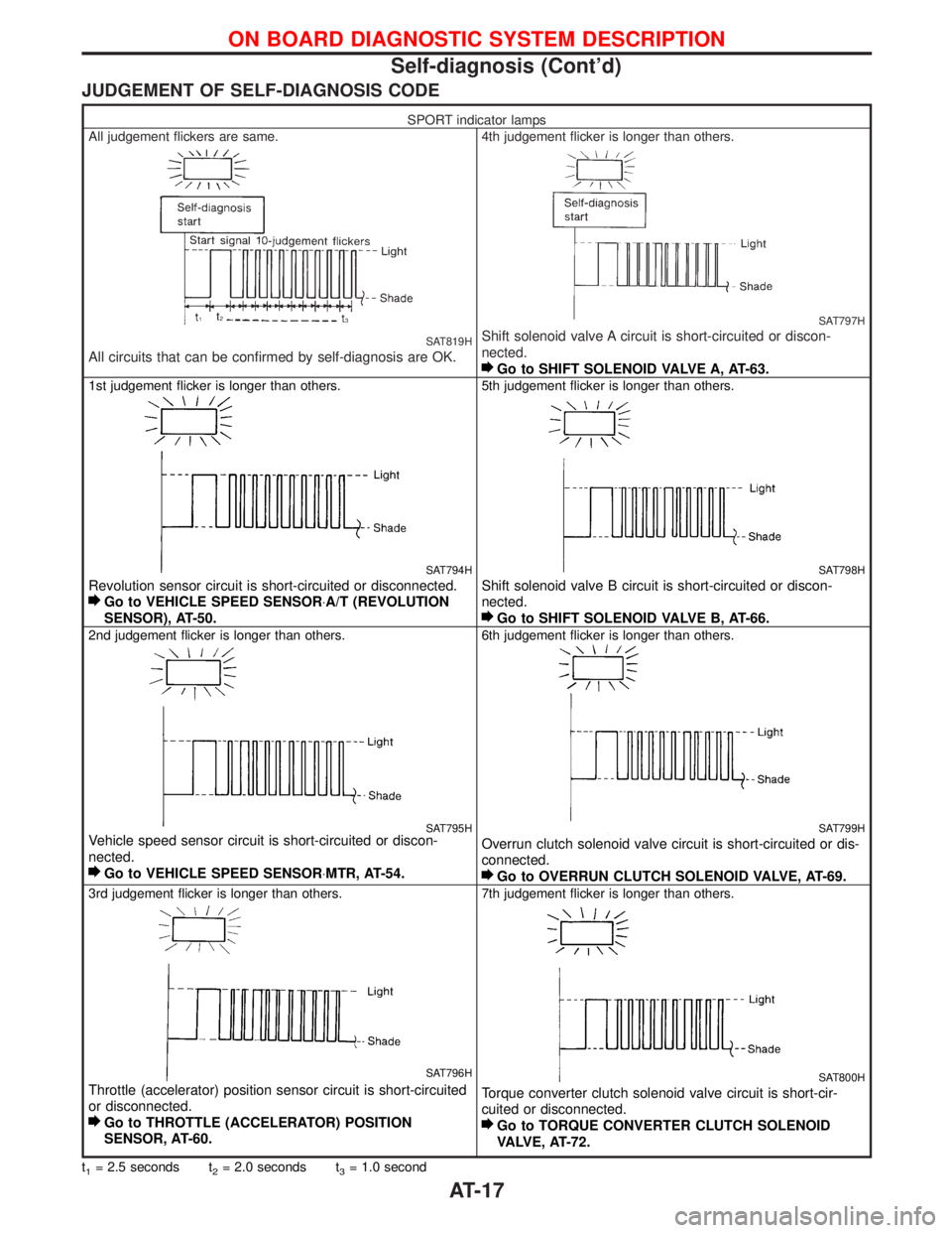
JUDGEMENT OF SELF-DIAGNOSIS CODE
SPORT indicator lamps
All judgement flickers are same.
SAT819H
All circuits that can be confirmed by self-diagnosis are OK.
4th judgement flicker is longer than others.
SAT797H
Shift solenoid valve A circuit is short-circuited or discon-
nected.
Go to SHIFT SOLENOID VALVE A, AT-63.
1st judgement flicker is longer than others.
SAT794H
Revolution sensor circuit is short-circuited or disconnected.
Go to VEHICLE SPEED SENSOR×A/T (REVOLUTION
SENSOR), AT-50.
5th judgement flicker is longer than others.
SAT798H
Shift solenoid valve B circuit is short-circuited or discon-
nected.
Go to SHIFT SOLENOID VALVE B, AT-66.
2nd judgement flicker is longer than others.
SAT795HVehicle speed sensor circuit is short-circuited or discon-
nected.
Go to VEHICLE SPEED SENSOR×MTR, AT-54.
6th judgement flicker is longer than others.
SAT799H
Overrun clutch solenoid valve circuit is short-circuited or dis-
connected.
Go to OVERRUN CLUTCH SOLENOID VALVE, AT-69.
3rd judgement flicker is longer than others.
SAT796H
Throttle (accelerator) position sensor circuit is short-circuited
or disconnected.
Go to THROTTLE (ACCELERATOR) POSITION
SENSOR, AT-60.
7th judgement flicker is longer than others.
SAT800H
Torque converter clutch solenoid valve circuit is short-cir-
cuited or disconnected.
Go to TORQUE CONVERTER CLUTCH SOLENOID
VALVE, AT-72.
t1= 2.5 seconds t2= 2.0 seconds t3= 1.0 second
ON BOARD DIAGNOSTIC SYSTEM DESCRIPTION
Self-diagnosis (Cont'd)
AT-17
Page 23 of 1767
![NISSAN TERRANO 2002 Service Repair Manual Item DisplayMonitor item
Description Remarks ECU
input
signalsMain
signals
ASCD-OD cut signal ASCD×OD CUT
[ON/OFF]
XÐIStatus of ASCD×OD release signal is
displayed.
ON ... OD released
OFF ... OD no NISSAN TERRANO 2002 Service Repair Manual Item DisplayMonitor item
Description Remarks ECU
input
signalsMain
signals
ASCD-OD cut signal ASCD×OD CUT
[ON/OFF]
XÐIStatus of ASCD×OD release signal is
displayed.
ON ... OD released
OFF ... OD no](/manual-img/5/57393/w960_57393-22.png)
Item DisplayMonitor item
Description Remarks ECU
input
signalsMain
signals
ASCD-OD cut signal ASCD×OD CUT
[ON/OFF]
XÐIStatus of ASCD×OD release signal is
displayed.
ON ... OD released
OFF ... OD not releasedIThis is displayed even when no
ASCD is mounted.
Kickdown switch KICKDOWN SW
[ON/OFF]XÐION/OFF status, computed from sig-
nal of kickdown SW, is displayed.IThis is displayed even when no
kickdown switch is equipped.
A/T mode switch POWER SHIFT SW
[ON/OFF]XÐION/OFF state computed from signal
of SPORT shift SW is displayed.
Closed throttle position
switchCLOSED THL/SW
[ON/OFF] X ÐION/OFF status, computed from sig-
nal of closed throttle (accelerator)
position SW, is displayed.
Wide open throttle posi-
tion switchW/O THRL/P-SW
[ON/OFF] X ÐION/OFF status, computed from sig-
nal of wide open throttle (accelera-
tor) position SW, is displayed.
A/T mode switch HOLD SW
[ON/OFF]XÐION/OFF status, computed from sig-
nal of SNOW shift SW, is displayed.
Gear position GEAR
ÐXIGear position data used for compu-
tation by TCM, is displayed.
Selector lever position SLCT LVR POSI
ÐXISelector lever position data, used
for computation by TCM, is dis-
played.IA specific value used for control is
displayed if fail-safe is activated due
to error.
Vehicle speed VEHICLE SPEED
[km/h] or [mph]ÐXIVehicle speed data, used for com-
putation by TCM, is displayed.
Throttle (accelerator)
positionTHROTTLE POSI
[/8] Ð XIThrottle (accelerator) position data,
used for computation by TCM, is
displayed.IA specific value used for control is
displayed if fail-safe is activated due
to error.
Line pressure duty LINE PRES DTY
[%] Ð XIControl value of line pressure sole-
noid valve, computed by TCM from
each input signal, is displayed.
Torque converter clutch
solenoid valve dutyTCC S/V DUTY
[%]
ÐXIControl value of torque converter
clutch solenoid valve, computed by
TCM from each input signal, is dis-
played.
Shift solenoid valve A SHIFT S/V A
[ON/OFF] Ð XIControl value of shift solenoid valve
A, computed by TCM from each
input signal, is displayed.Control value of solenoid is displayed
even if solenoid circuit is discon-
nected.
The ªOFFº signal is displayed if sole-
noid circuit is shorted. Shift solenoid valve B SHIFT S/V B
[ON/OFF] Ð XIControl value of shift solenoid valve
B, computed by TCM from each
input signal, is displayed.
Overrun clutch solenoid
valveOVERRUN/C S/V
[ON/OFF] Ð XIControl value of overrun clutch sole-
noid valve computed by TCM from
each input signal is displayed.
Self-diagnosis display
lamp
(SPORT indicator lamp)SELF-D DP LMP
[ON/OFF] Ð XIControl status of SPORT indicator
lamp is displayed.
X: Applicable
Ð: Not applicable
ON BOARD DIAGNOSTIC SYSTEM DESCRIPTION
Diagnosis by CONSULT-II (Cont'd)
AT-21
Page 26 of 1767
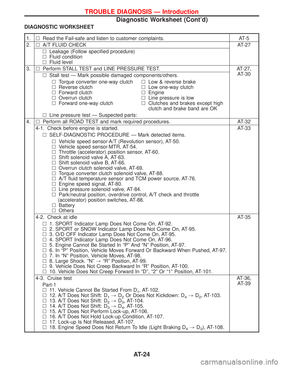
DIAGNOSTIC WORKSHEET
1.lRead the Fail-safe and listen to customer complaints. AT-5
2.lA/T FLUID CHECK AT-27
lLeakage (Follow specified procedure)
lFluid condition
lFluid level
3.lPerform STALL TEST and LINE PRESSURE TEST. AT-27,
AT-30
lStall test Ð Mark possible damaged components/others.
lTorque converter one-way clutch
lReverse clutch
lForward clutch
lOverrun clutch
lForward one-way clutchlLow & reverse brake
lLow one-way clutch
lEngine
lLine pressure is low
lClutches and brakes except high
clutch and brake band are OK
lLine pressure test Ð Suspected parts:
4.lPerform all ROAD TEST and mark required procedures. AT-32
4-1. Check before engine is started. AT-33
lSELF-DIAGNOSTIC PROCEDURE Ð Mark detected items.
lVehicle speed sensor×A/T (Revolution sensor), AT-50.
lVehicle speed sensor×MTR, AT-54.
lThrottle (accelerator) position sensor, AT-60.
lShift solenoid valve A, AT-63.
lShift solenoid valve B, AT-66.
lOverrun clutch solenoid valve, AT-69.
lTorque converter clutch solenoid valve, AT-88.
lA/T fluid temperature sensor and TCM power source, AT-76.
lEngine speed signal, AT-80.
lLine pressure solenoid valve, AT-84.
lPark/neutral position, overdrive control, A/T check and throttle
(accelerator) position switches, AT-88.
lBattery
lOthers
4-2. Check at idle AT-35
l1. SPORT Indicator Lamp Does Not Come On, AT-92.
l2. SPORT or SNOW Indicator Lamp Does Not Come On, AT-95.
l3. O/D OFF Indicator Lamp Does Not Come On, AT-95.
l4. SPORT Indicator Lamp Does Not Come On, AT-96.
l5. Engine Cannot Be Started In ªPº And ªNº Position, AT-97.
l6. In ªPº Position, Vehicle Moves Forward Or Backward When Pushed, AT-97.
l7. In ªNº Position, Vehicle Moves, AT-98.
l8. Large Shock. ªNº,ªRº Position, AT-99.
l9. Vehicle Does Not Creep Backward In ªRº Position, AT-100.
l10. Vehicle Does Not Creep Forward In ªDº, ª2º Or ª1º Position, AT-101.
4-3. Cruise testAT-36,
AT-39
Part-1
l11. Vehicle Cannot Be Started From D
1, AT-102.
l12. A/T Does Not Shift: D
1,D2Or Does Not Kickdown: D4,D2, AT-103.
l13. A/T Does Not Shift: D
2,D3, AT-104.
l14. A/T Does Not Shift: D
3,D4, AT-105.
l15. A/T Does Not Perform Lock-up, AT-106.
l16. A/T Does Not Hold Lock-up Condition, AT-107.
l17. Lock-up Is Not Released, AT-107.
l18. Engine Speed Does Not Return To Idle (Light Braking D
4,D3), AT-108.
TROUBLE DIAGNOSIS Ð Introduction
Diagnostic Worksheet (Cont'd)
AT-24
Page 27 of 1767
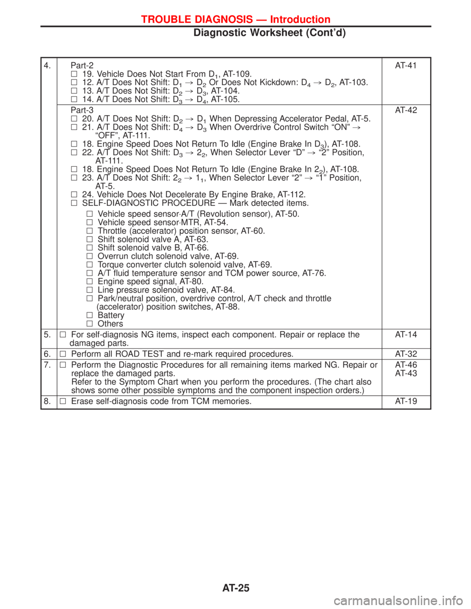
4. Part-2
l19. Vehicle Does Not Start From D
1, AT-109.
l12. A/T Does Not Shift: D
1,D2Or Does Not Kickdown: D4,D2, AT-103.
l13. A/T Does Not Shift: D
2,D3, AT-104.
l14. A/T Does Not Shift: D
3,D4, AT-105.AT-41
Part-3
l20. A/T Does Not Shift: D
2,D1When Depressing Accelerator Pedal, AT-5.
l21. A/T Does Not Shift: D
4,D3When Overdrive Control Switch ªONº,
ªOFFº, AT-111.
l18. Engine Speed Does Not Return To Idle (Engine Brake In D
3), AT-108.
l22. A/T Does Not Shift: D
3,22, When Selector Lever ªDº,ª2º Position,
AT- 111 .
l18. Engine Speed Does Not Return To Idle (Engine Brake In 2
2), AT-108.
l23. A/T Does Not Shift: 2
2,11, When Selector Lever ª2º,ª1º Position,
AT-5.
l24. Vehicle Does Not Decelerate By Engine Brake, AT-112.
lSELF-DIAGNOSTIC PROCEDURE Ð Mark detected items.AT-42
lVehicle speed sensor×A/T (Revolution sensor), AT-50.
lVehicle speed sensor×MTR, AT-54.
lThrottle (accelerator) position sensor, AT-60.
lShift solenoid valve A, AT-63.
lShift solenoid valve B, AT-66.
lOverrun clutch solenoid valve, AT-69.
lTorque converter clutch solenoid valve, AT-69.
lA/T fluid temperature sensor and TCM power source, AT-76.
lEngine speed signal, AT-80.
lLine pressure solenoid valve, AT-84.
lPark/neutral position, overdrive control, A/T check and throttle
(accelerator) position switches, AT-88.
lBattery
lOthers
5.lFor self-diagnosis NG items, inspect each component. Repair or replace the
damaged parts.AT-14
6.lPerform all ROAD TEST and re-mark required procedures. AT-32
7.lPerform the Diagnostic Procedures for all remaining items marked NG. Repair or
replace the damaged parts.
Refer to the Symptom Chart when you perform the procedures. (The chart also
shows some other possible symptoms and the component inspection orders.)AT-46
AT-43
8.lErase self-diagnosis code from TCM memories. AT-19
TROUBLE DIAGNOSIS Ð Introduction
Diagnostic Worksheet (Cont'd)
AT-25
Page 30 of 1767
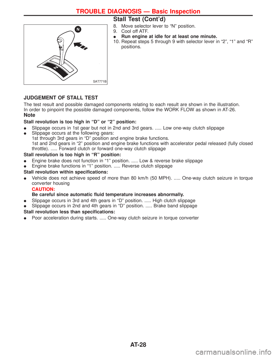
8. Move selector lever to ªNº position.
9. Cool off ATF.
IRun engine at idle for at least one minute.
10. Repeat steps 5 through 9 with selector lever in ª2º, ª1º and ªRº
positions.
JUDGEMENT OF STALL TEST
The test result and possible damaged components relating to each result are shown in the illustration.
In order to pinpoint the possible damaged components, follow the WORK FLOW as shown in AT-26.
Note
Stall revolution is too high in ªDº or ª2º position:
ISlippage occurs in 1st gear but not in 2nd and 3rd gears. ..... Low one-way clutch slippage
ISlippage occurs at the following gears:
1st through 3rd gears in ªDº position and engine brake functions.
1st and 2nd gears in ª2º position and engine brake functions with accelerator pedal released (fully closed
throttle). ..... Forward clutch or forward one-way clutch slippage
Stall revolution is too high in ªRº position:
IEngine brake does not function in ª1º position. ..... Low & reverse brake slippage
IEngine brake functions in ª1º position. ..... Reverse clutch slippage
Stall revolution within specifications:
IVehicle does not achieve speed of more than 80 km/h (50 MPH). ..... One-way clutch seizure in torque
converter housing
CAUTION:
Be careful since automatic fluid temperature increases abnormally.
ISlippage occurs in 3rd and 4th gears in ªDº position. ..... High clutch slippage
ISlippage occurs in 2nd and 4th gears in ªDº position. ..... Brake band slippage
Stall revolution less than specifications:
IPoor acceleration during starts. ..... One-way clutch seizure in torque converter
SAT771B
TROUBLE DIAGNOSIS Ð Basic Inspection
Stall Test (Cont'd)
AT-28
Page 33 of 1767
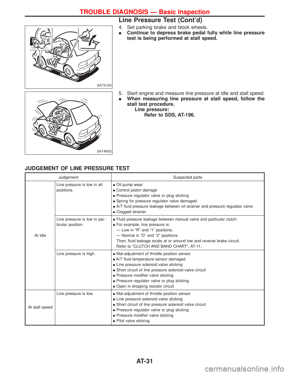
4. Set parking brake and block wheels.
IContinue to depress brake pedal fully while line pressure
test is being performed at stall speed.
5. Start engine and measure line pressure at idle and stall speed.
IWhen measuring line pressure at stall speed, follow the
stall test procedure.
Line pressure:
Refer to SDS, AT-196.
JUDGEMENT OF LINE PRESSURE TEST
Judgement Suspected parts
At idleLine pressure is low in all
positions.IOil pump wear
IControl piston damage
IPressure regulator valve or plug sticking
ISpring for pressure regulator valve damaged
IA/T fluid pressure leakage between oil strainer and pressure regulator valve
IClogged strainer
Line pressure is low in par-
ticular position.IFluid pressure leakage between manual valve and particular clutch
IFor example, line pressure is:
Ð Low in ªRº and ª1º positions,
Ð Normal in ªDº and ª2º positions.
Then, fluid leakage exists at or around low and reverse brake circuit.
Refer to ªCLUTCH AND BAND CHARTº, AT-11.
Line pressure is high.IMal-adjustment of throttle position sensor
IA/T fluid temperature sensor damaged
ILine pressure solenoid valve sticking
IShort circuit of line pressure solenoid valve circuit
IPressure modifier valve sticking
IPressure regulator valve or plug sticking
IOpen in dropping resistor circuit
At stall speedLine pressure is low.IMal-adjustment of throttle position sensor
ILine pressure solenoid valve sticking
IShort circuit of line pressure solenoid valve circuit
IPressure regulator valve or plug sticking
IPressure modifier valve sticking
IPilot valve sticking
SAT513G
SAT493G
TROUBLE DIAGNOSIS Ð Basic Inspection
Line Pressure Test (Cont'd)
AT-31
Page 45 of 1767
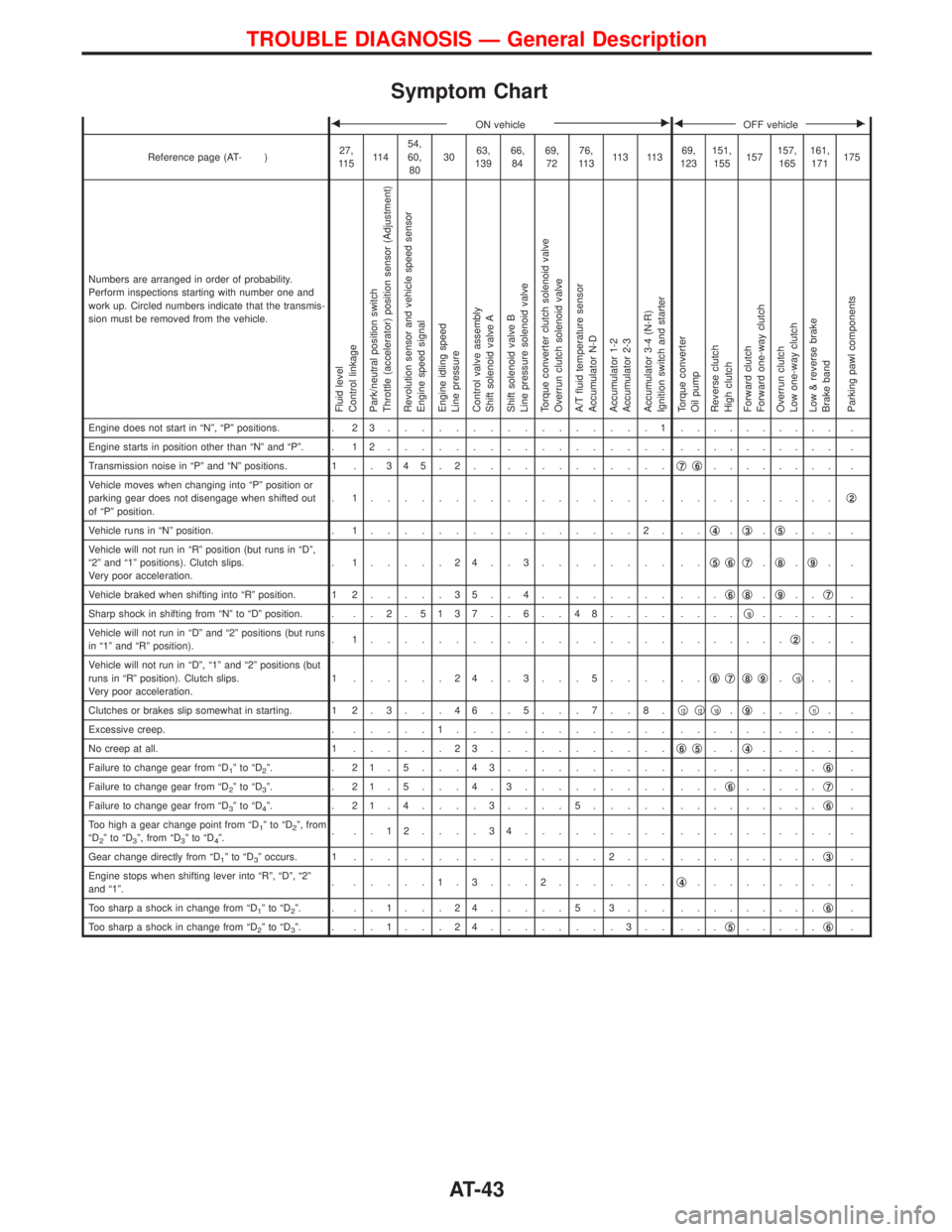
Symptom Chart
FON vehicleEFOFF vehicleE
Reference page (AT- )27,
11 511 454,
60,
803063,
13966,
8469,
7276,
11 311 3 11 369,
123151,
155157157,
165161,
171175
Numbers are arranged in order of probability.
Perform inspections starting with number one and
work up. Circled numbers indicate that the transmis-
sion must be removed from the vehicle.
Fluid level
Control linkage
Park/neutral position switch
Throttle (accelerator) position sensor (Adjustment)
Revolution sensor and vehicle speed sensor
Engine speed signal
Engine idling speed
Line pressure
Control valve assembly
Shift solenoid valve A
Shift solenoid valve B
Line pressure solenoid valve
Torque converter clutch solenoid valve
Overrun clutch solenoid valve
A/T fluid temperature sensor
Accumulator N-D
Accumulator 1-2
Accumulator 2-3
Accumulator 3-4 (N-R)
Ignition switch and starter
Torque converter
Oil pump
Reverse clutch
High clutch
Forward clutch
Forward one-way clutch
Overrun clutch
Low one-way clutch
Low & reverse brake
Brake band
Parking pawl components
Engine does not start in ªNº, ªPº positions. . 2 3................1.......... .
Engine starts in position other than ªNº and ªPº. . 1 2................. .......... .
Transmission noise in ªPº and ªNº positions. 1 . . 3 4 5 . 2............q
7q6........ .
Vehicle moves when changing into ªPº position or
parking gear does not disengage when shifted out
of ªPº position.. 1.................. ..........q
2
Vehicle runs in ªNº position. . 1................2. ..q4.q3.q5... .
Vehicle will not run in ªRº position (but runs in ªDº,
ª2º and ª1º positions). Clutch slips.
Very poor acceleration.. 1.....24..3........ ..q
5q6q7.q8.q9..
Vehicle braked when shifting into ªRº position. 1 2.....35..4........ ...q
6q8.q9..q7.
Sharp shock in shifting from ªNº to ªDº position. . . . 2 .5137 . . 6 . . 48.... ....q
10..... .
Vehicle will not run in ªDº and ª2º positions (but runs
in ª1º and ªRº position).. 1.................. .......q
2.. .
Vehicle will not run in ªDº, ª1º and ª2º positions (but
runs in ªRº position). Clutch slips.
Very poor acceleration.1 ......24..3...5.... ..q
6q7q8q9.q10.. .
Clutches or brakes slip somewhat in starting. 1 2 . 3 . . . 4 6 . . 5 . . . 7 . . 8 .q
13q12q10.q9...q11..
Excessive creep. ......1............. .......... .
No creep at all. 1......23...........q
6q5..q4..... .
Failure to change gear from ªD
1ºtoªD2º. . 21.5...43.......... .........q6.
Failure to change gear from ªD
2ºtoªD3º. . 21.5...4.3......... ...q6.....q7.
Failure to change gear from ªD
3ºtoªD4º. . 21.4....3....5..... .........q6.
Too high a gear change point from ªD
1ºtoªD2º, from
ªD2ºtoªD3º, from ªD3ºtoªD4º.. ..12....34......... .......... .
Gear change directly from ªD
1ºtoªD3º occurs. 1...............2... .........q3.
Engine stops when shifting lever into ªRº, ªDº, ª2º
and ª1º.. .....1.3...2.......q
4......... .
Too sharp a shock in change from ªD
1ºtoªD2º. . ..1...24.....5.3... .........q6.
Too sharp a shock in change from ªD
2ºtoªD3º. . ..1...24........3.. ...q5.....q6.
TROUBLE DIAGNOSIS Ð General Description
AT-43