Page 497 of 1767
Diagnostic Procedure
1 CHECK OVERALL FUNCTION-I
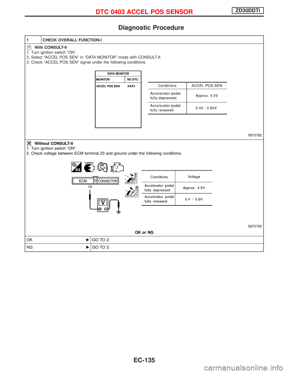
With CONSULT-II
1. Turn ignition switch ªONº.
2. Select ªACCEL POS SENº in ªDATA MONITORº mode with CONSULT-II.
3. Check ªACCEL POS SENº signal under the following conditions.
SEF278Z
Without CONSULT-II
1. Turn ignition switch ªONº.
2. Check voltage between ECM terminal 23 and ground under the following conditions.
SEF279Z
OK or NG
OKEGO TO 2.
NGEGO TO 3.
DTC 0403 ACCEL POS SENSORZD30DDTi
EC-135
Page 498 of 1767
2 CHECK OVERALL FUNCTION-II
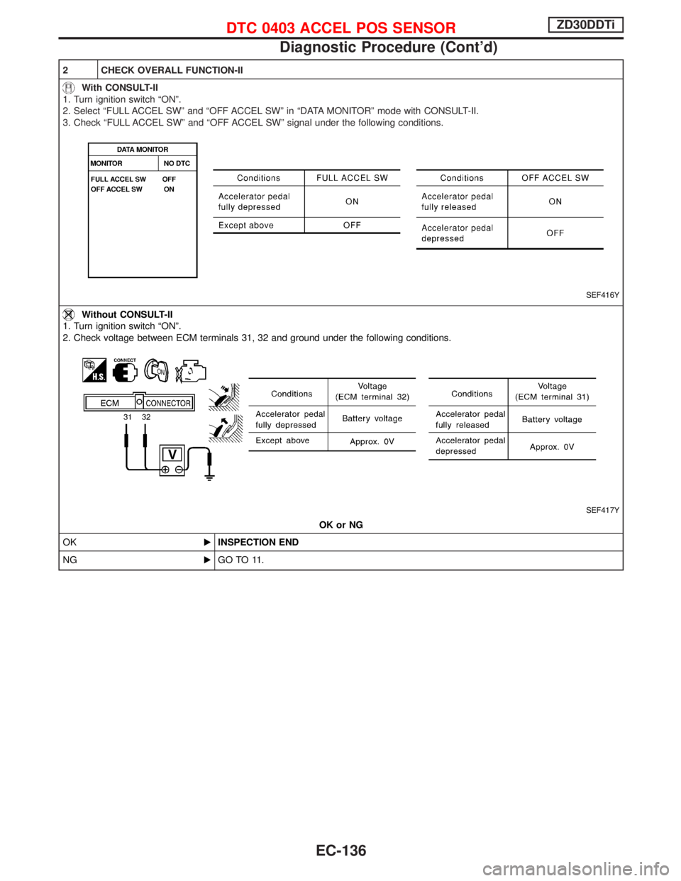
With CONSULT-II
1. Turn ignition switch ªONº.
2. Select ªFULL ACCEL SWº and ªOFF ACCEL SWº in ªDATA MONITORº mode with CONSULT-II.
3. Check ªFULL ACCEL SWº and ªOFF ACCEL SWº signal under the following conditions.
SEF416Y
Without CONSULT-II
1. Turn ignition switch ªONº.
2. Check voltage between ECM terminals 31, 32 and ground under the following conditions.
SEF417Y
OK or NG
OKEINSPECTION END
NGEGO TO 11.
DTC 0403 ACCEL POS SENSORZD30DDTi
Diagnostic Procedure (Cont'd)
EC-136
Page 500 of 1767
4 CHECK ACCELERATOR POSITION SENSOR GROUND CIRCUIT FOR OPEN AND SHORT
1. Turn ignition switch ªOFFº.
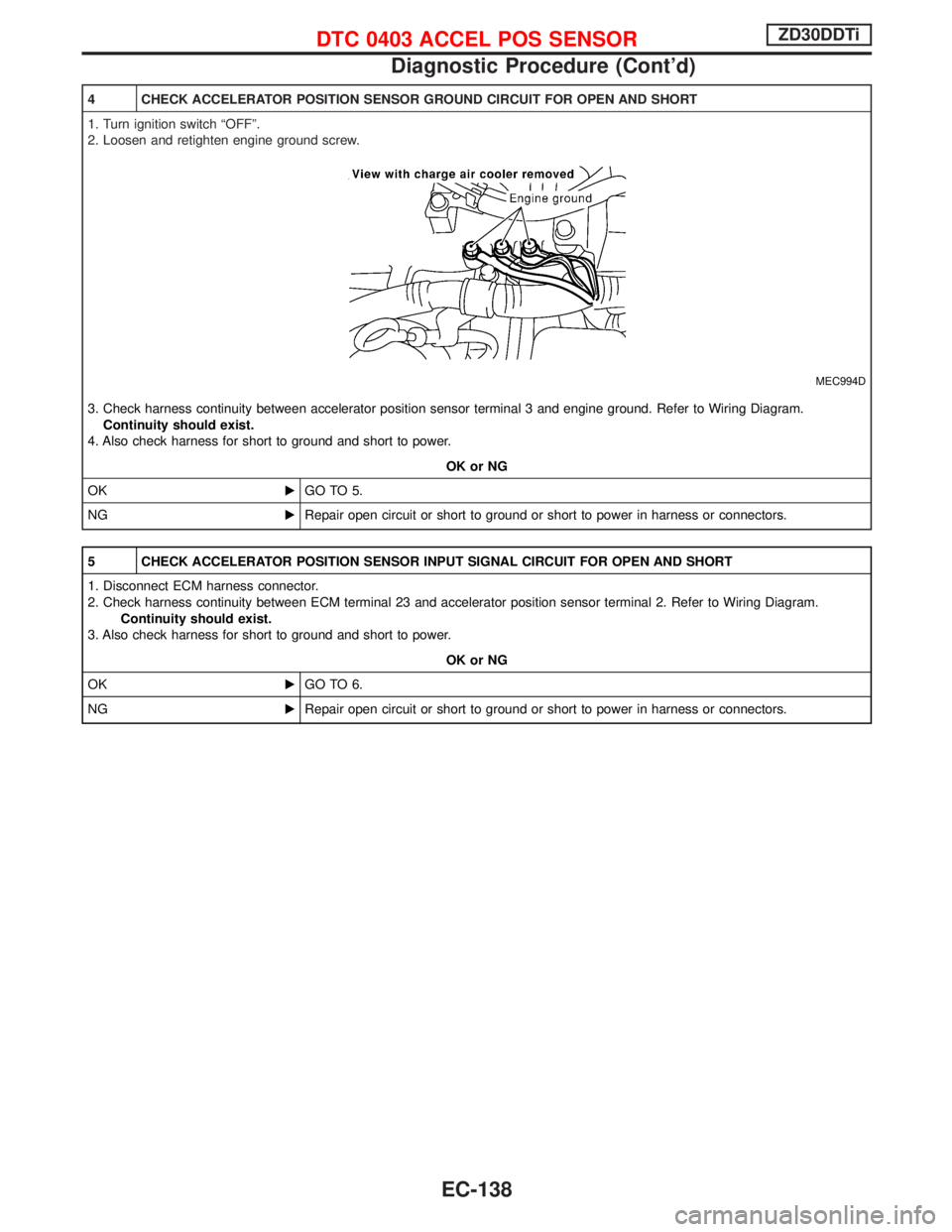
2. Loosen and retighten engine ground screw.
MEC994D
3. Check harness continuity between accelerator position sensor terminal 3 and engine ground. Refer to Wiring Diagram.
Continuity should exist.
4. Also check harness for short to ground and short to power.
OK or NG
OKEGO TO 5.
NGERepair open circuit or short to ground or short to power in harness or connectors.
5 CHECK ACCELERATOR POSITION SENSOR INPUT SIGNAL CIRCUIT FOR OPEN AND SHORT
1. Disconnect ECM harness connector.
2. Check harness continuity between ECM terminal 23 and accelerator position sensor terminal 2. Refer to Wiring Diagram.
Continuity should exist.
3. Also check harness for short to ground and short to power.
OK or NG
OKEGO TO 6.
NGERepair open circuit or short to ground or short to power in harness or connectors.
DTC 0403 ACCEL POS SENSORZD30DDTi
Diagnostic Procedure (Cont'd)
EC-138
Page 503 of 1767
13 CHECK ACCELERATOR POSITION SWITCH INPUT SIGNAL CIRCUIT-I FOR OPEN AND SHORT
1. Turn ignition switch ªOFFº.
2. Disconnect ECM harness connector.
3. Check harness continuity between accelerator position switch terminal 6 and ECM terminal 31. Refer to Wiring Diagram.
Continuity should exist.
4. Also check harness for short to ground and short to power.
OK or NG
OKEGO TO 14.
NGERepair open circuit or short to ground or short to power in harness or connectors.
14 CHECK ACCELERATOR POSITION SWITCH INPUT SIGNAL CIRCUIT-II FOR OPEN AND SHORT
1. Check harness continuity between accelerator position switch terminal 4 and ECM terminal 32. Refer to Wiring Diagram.
Continuity should exist.
2. Also check harness for short to ground and short to power.
OK or NG
OKEGO TO 15.
NGERepair open circuit or short to ground or short to power in harness or connectors.
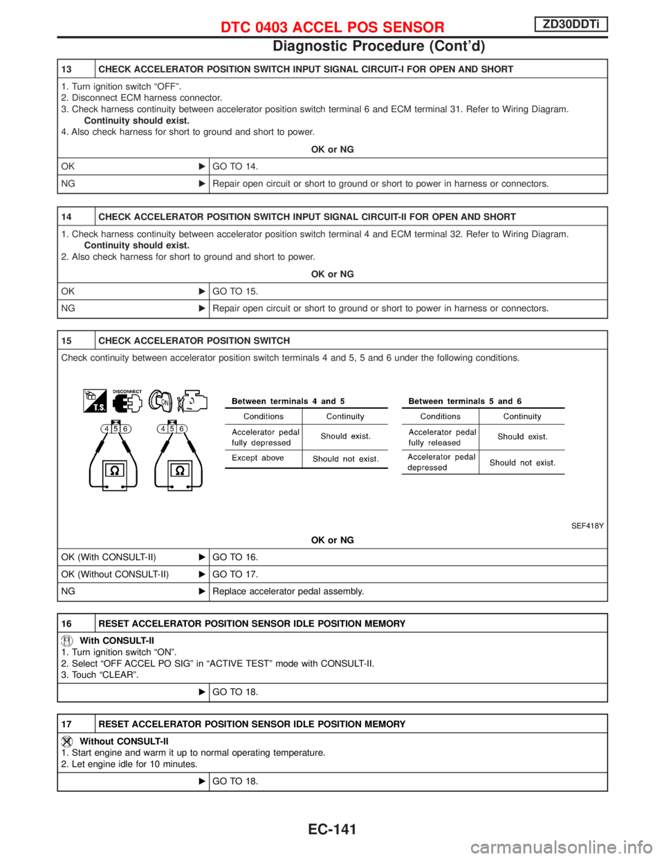
15 CHECK ACCELERATOR POSITION SWITCH
Check continuity between accelerator position switch terminals 4 and 5, 5 and 6 under the following conditions.
SEF418Y
OK or NG
OK (With CONSULT-II)EGO TO 16.
OK (Without CONSULT-II)EGO TO 17.
NGEReplace accelerator pedal assembly.
16 RESET ACCELERATOR POSITION SENSOR IDLE POSITION MEMORY
With CONSULT-II
1. Turn ignition switch ªONº.
2. Select ªOFF ACCEL PO SIGº in ªACTIVE TESTº mode with CONSULT-II.
3. Touch ªCLEARº.
EGO TO 18.
17 RESET ACCELERATOR POSITION SENSOR IDLE POSITION MEMORY
Without CONSULT-II
1. Start engine and warm it up to normal operating temperature.
2. Let engine idle for 10 minutes.
EGO TO 18.
DTC 0403 ACCEL POS SENSORZD30DDTi
Diagnostic Procedure (Cont'd)
EC-141
Page 506 of 1767
Diagnostic Procedure
1 CHECK INTAKE AIR LEAK
Listen for an intake air leak after the mass air flow sensor.
OK or NG
OKEGO TO 2.
NGERepair or replace.
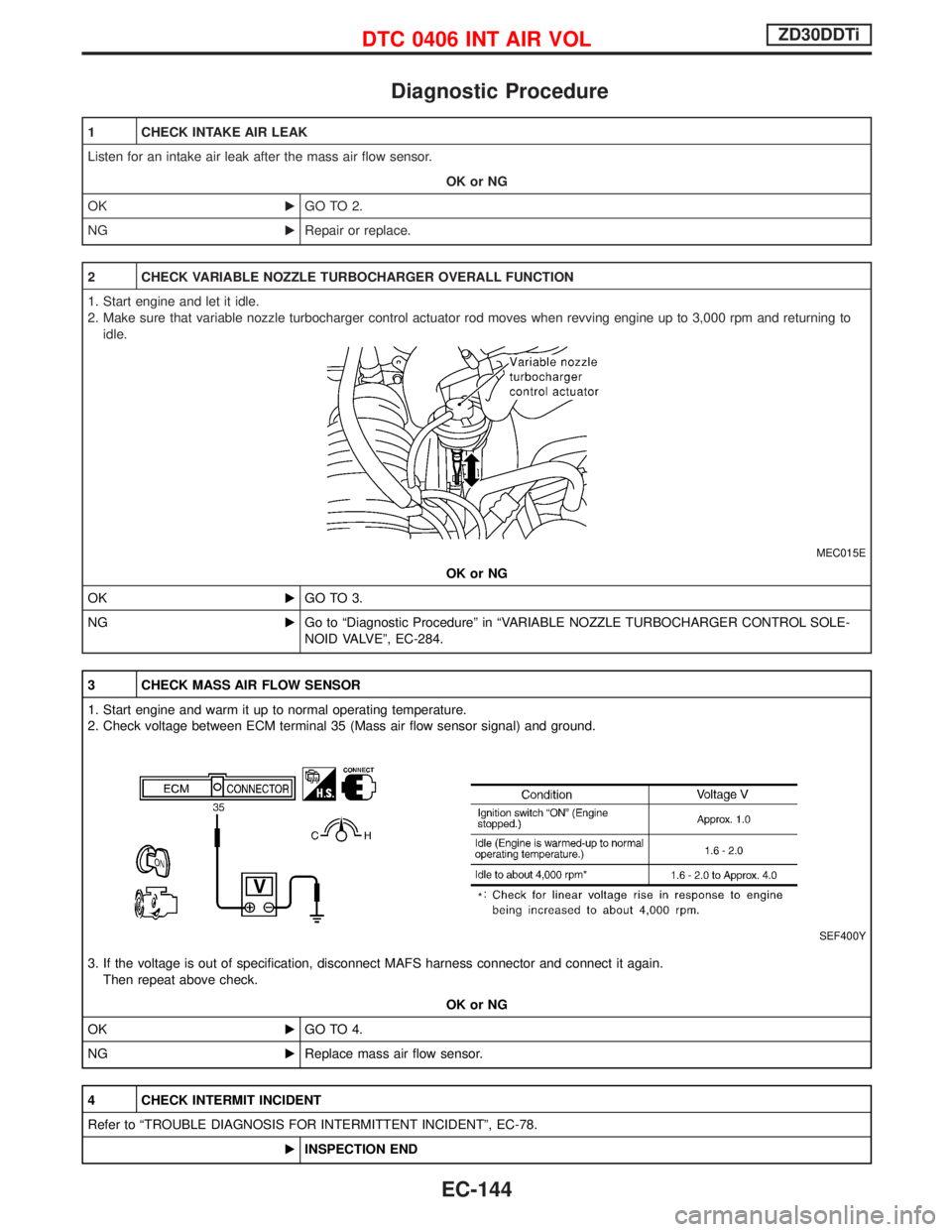
2 CHECK VARIABLE NOZZLE TURBOCHARGER OVERALL FUNCTION
1. Start engine and let it idle.
2. Make sure that variable nozzle turbocharger control actuator rod moves when revving engine up to 3,000 rpm and returning to
idle.
MEC015E
OK or NG
OKEGO TO 3.
NGEGo to ªDiagnostic Procedureº in ªVARIABLE NOZZLE TURBOCHARGER CONTROL SOLE-
NOID VALVEº, EC-284.
3 CHECK MASS AIR FLOW SENSOR
1. Start engine and warm it up to normal operating temperature.
2. Check voltage between ECM terminal 35 (Mass air flow sensor signal) and ground.
SEF400Y
3. If the voltage is out of specification, disconnect MAFS harness connector and connect it again.
Then repeat above check.
OK or NG
OKEGO TO 4.
NGEReplace mass air flow sensor.
4 CHECK INTERMIT INCIDENT
Refer to ªTROUBLE DIAGNOSIS FOR INTERMITTENT INCIDENTº, EC-78.
EINSPECTION END
DTC 0406 INT AIR VOLZD30DDTi
EC-144
Page 508 of 1767
On Board Diagnosis Logic
Malfunction is detected when ... Check Items (Possible Cause)
IAn improper signal from the sensor is sent to ECM during
engine running and cranking.IHarness or connectors
(The sensor circuit is open.)
ICrankshaft position sensor (TDC)
DTC Confirmation Procedure
Before performing the following procedure, confirm that bat-
tery voltage is more than 10V.
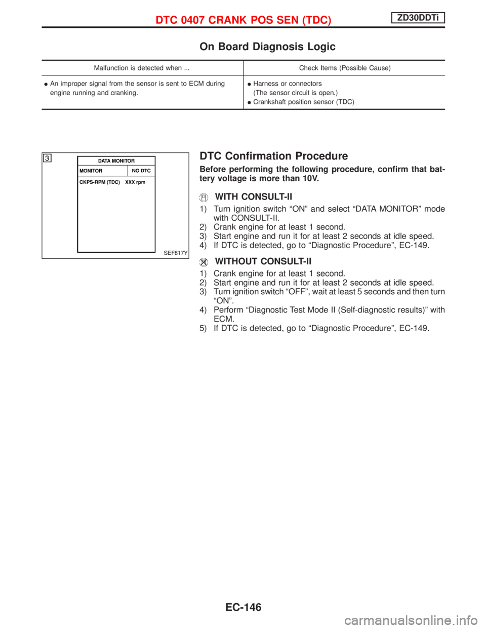
WITH CONSULT-II
1) Turn ignition switch ªONº and select ªDATA MONITORº mode
with CONSULT-II.
2) Crank engine for at least 1 second.
3) Start engine and run it for at least 2 seconds at idle speed.
4) If DTC is detected, go to ªDiagnostic Procedureº, EC-149.
WITHOUT CONSULT-II
1) Crank engine for at least 1 second.
2) Start engine and run it for at least 2 seconds at idle speed.
3) Turn ignition switch ªOFFº, wait at least 5 seconds and then turn
ªONº.
4) Perform ªDiagnostic Test Mode II (Self-diagnostic results)º with
ECM.
5) If DTC is detected, go to ªDiagnostic Procedureº, EC-149.
SEF817Y
DTC 0407 CRANK POS SEN (TDC)ZD30DDTi
EC-146
Page 518 of 1767
DTC Confirmation Procedure
NOTE:
If ªDTC Confirmation Procedureº has been previously
conducted, always turn ignition switch ªOFFº and wait at least
5 seconds before conducting the next test.
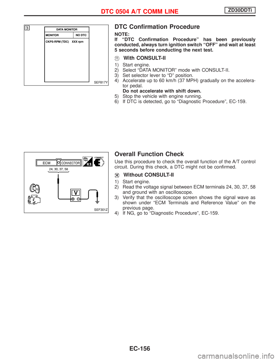
With CONSULT-II
1) Start engine.
2) Select ªDATA MONITORº mode with CONSULT-II.
3) Set selector lever to ªDº position.
4) Accelerate up to 60 km/h (37 MPH) gradually on the accelera-
tor pedal.
Do not accelerate with shift down.
5) Stop the vehicle with engine running.
6) If DTC is detected, go to ªDiagnostic Procedureº, EC-159.
Overall Function Check
Use this procedure to check the overall function of the A/T control
circuit. During this check, a DTC might not be confirmed.
Without CONSULT-II
1) Start engine.
2) Read the voltage signal between ECM terminals 24, 30, 37, 58
and ground with an oscilloscope.
3) Verify that the oscilloscope screen shows the signal wave as
shown under ªECM Terminals and Reference Valueº on the
previous page.
4) If NG, go to ªDiagnostic Procedureº, EC-159.
SEF817Y
SEF301Z
DTC 0504 A/T COMM LINEZD30DDTi
EC-156
Page 521 of 1767
Diagnostic Procedure
1 CHECK INPUT SIGNAL CIRCUIT
1. Turn ignition switch ªOFFº.
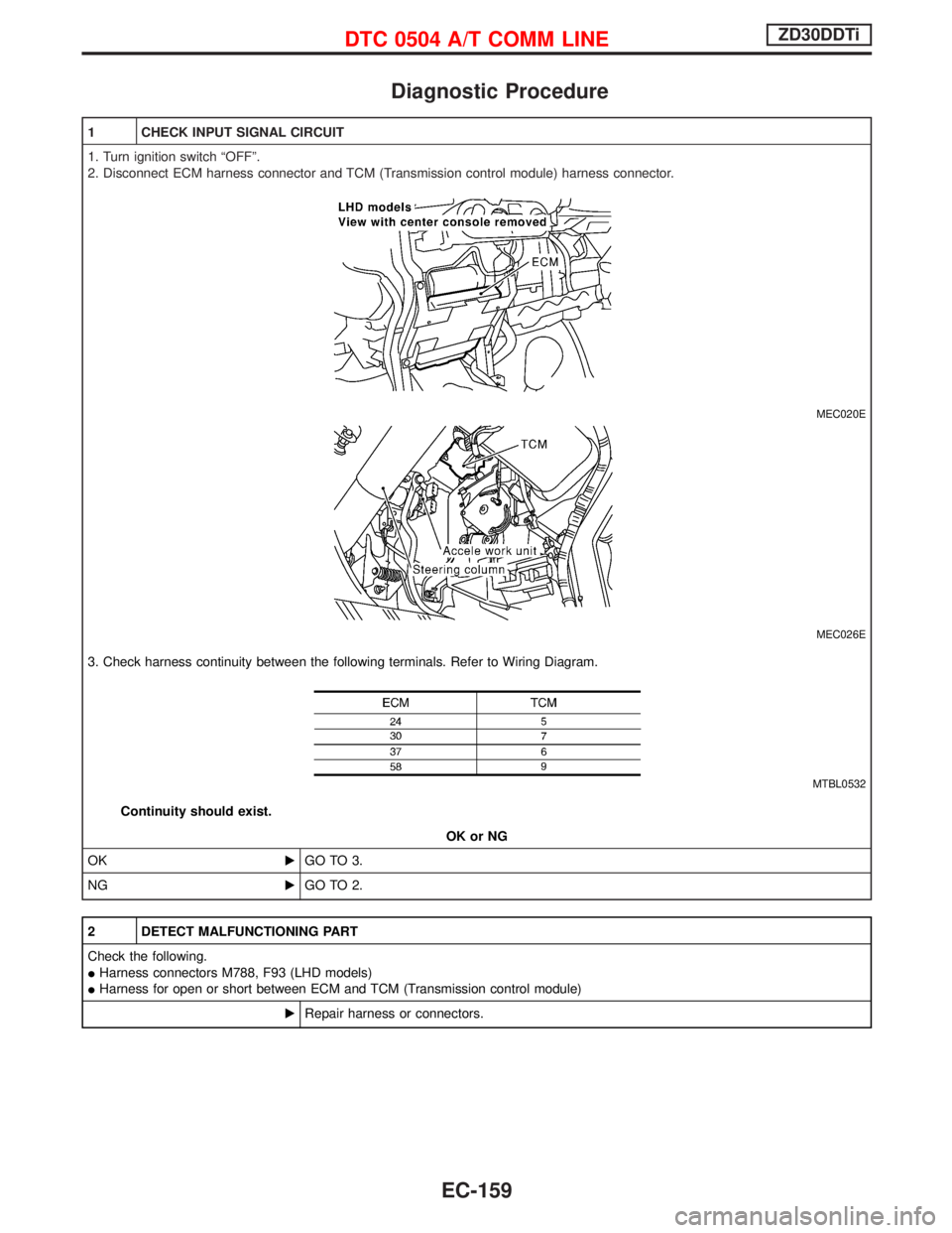
2. Disconnect ECM harness connector and TCM (Transmission control module) harness connector.
MEC020E
MEC026E
3. Check harness continuity between the following terminals. Refer to Wiring Diagram.
MTBL0532
Continuity should exist.
OK or NG
OKEGO TO 3.
NGEGO TO 2.
2 DETECT MALFUNCTIONING PART
Check the following.
IHarness connectors M788, F93 (LHD models)
IHarness for open or short between ECM and TCM (Transmission control module)
ERepair harness or connectors.
DTC 0504 A/T COMM LINEZD30DDTi
EC-159