2002 NISSAN TERRANO turn signal
[x] Cancel search: turn signalPage 110 of 1767
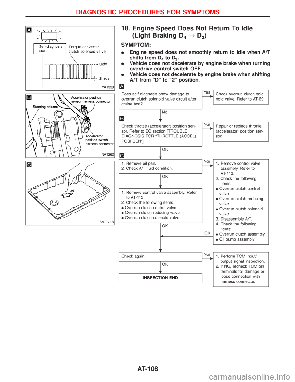
18. Engine Speed Does Not Return To Idle
(Light Braking D
4®D3)
SYMPTOM:
IEngine speed does not smoothly return to idle when A/T
shifts from D
4to D3.
IVehicle does not decelerate by engine brake when turning
overdrive control switch OFF.
IVehicle does not decelerate by engine brake when shifting
A/T from ªDº to ª2º position.
Does self-diagnosis show damage to
overrun clutch solenoid valve circuit after
cruise test?
No
EYe s
Check overrun clutch sole-
noid valve. Refer to AT-69.
Check throttle (accelerator) position sen-
sor. Refer to EC section [TROUBLE
DIAGNOSIS FOR ªTHROTTLE (ACCEL)
POSI SENº].
OK
ENG
Repair or replace throttle
(accelerator) position sen-
sor.
1. Remove oil pan.
2. Check A/T fluid condition.
OK
ENG
1. Remove control valve
assembly. Refer to
AT-113.
2. Check the following
items:
IOverrun clutch control
valve
IOverrun clutch reducing
valve
IOverrun clutch solenoid
valve
3. Disassemble A/T.
4. Check the following
items:
IOverrun clutch assembly
IOil pump assembly
1. Remove control valve assembly. Refer
to AT-113.
2. Check the following items:
IOverrun clutch control valve
IOverrun clutch reducing valve
IOverrun clutch solenoid valve
OK
FOK
Check again.
OK
ENG
1. Perform TCM input/
output signal inspection.
2. If NG, recheck TCM pin
terminals for damage or
loose connection with
harness connector.
INSPECTION END
YAT338
NAT262
SAT171B
H
H
H
H H
H
DIAGNOSTIC PROCEDURES FOR SYMPTOMS
AT-108
Page 114 of 1767
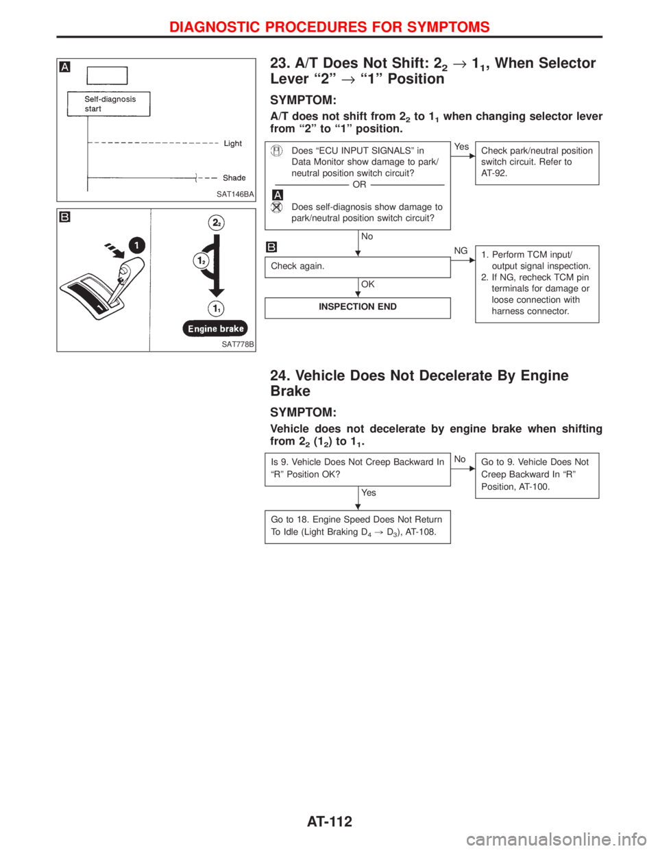
23. A/T Does Not Shift: 22®11, When Selector
Lever ª2º®ª1º Position
SYMPTOM:
A/T does not shift from 22to 11when changing selector lever
from ª2º to ª1º position.
Does ªECU INPUT SIGNALSº in
Data Monitor show damage to park/
neutral position switch circuit?
-----------------------------------------------------------------------------------------------------------------------OR -----------------------------------------------------------------------------------------------------------------------
Does self-diagnosis show damage to
park/neutral position switch circuit?
No
EYe s
Check park/neutral position
switch circuit. Refer to
AT-92.
Check again.
OK
ENG
1. Perform TCM input/
output signal inspection.
2. If NG, recheck TCM pin
terminals for damage or
loose connection with
harness connector.
INSPECTION END
24. Vehicle Does Not Decelerate By Engine
Brake
SYMPTOM:
Vehicle does not decelerate by engine brake when shifting
from 2
2(12)to11.
Is 9. Vehicle Does Not Creep Backward In
ªRº Position OK?
Ye s
ENo
Go to 9. Vehicle Does Not
Creep Backward In ªRº
Position, AT-100.
Go to 18. Engine Speed Does Not Return
To Idle (Light Braking D
4,D3), AT-108.
SAT146BA
SAT778B
H
H
H
DIAGNOSTIC PROCEDURES FOR SYMPTOMS
AT-112
Page 262 of 1767
![NISSAN TERRANO 2002 Service Repair Manual SELF-DIAGNOSTIC RESULTS MODE
Diagnostic item Diagnostic item is detected when...Diagnostic
procedure
FR RH SENSORH
[OPEN]ICircuit for front right wheel sensor is open.
(An abnormally high input voltag](/manual-img/5/57393/w960_57393-261.png "NISSAN TERRANO 2002 Service Repair Manual SELF-DIAGNOSTIC RESULTS MODE
Diagnostic item Diagnostic item is detected when...Diagnostic
procedure
FR RH SENSORH
[OPEN]ICircuit for front right wheel sensor is open.
(An abnormally high input voltag")
SELF-DIAGNOSTIC RESULTS MODE
Diagnostic item Diagnostic item is detected when...Diagnostic
procedure
FR RH SENSORH
[OPEN]ICircuit for front right wheel sensor is open.
(An abnormally high input voltage is entered.)4
FR LH SENSORH
[OPEN]ICircuit for front left wheel sensor is open.
(An abnormally high input voltage is entered.)4
RR RH SENSORH
[OPEN]ICircuit for rear right sensor is open.
(An abnormally high input voltage is entered.)4
RR LH SENSORH
[OPEN]ICircuit for rear left sensor is open.
(An abnormally high input voltage is entered.)4
FR RH SENSORH
[SHORT]ICircuit for front right wheel sensor is shorted.
(An abnormally low input voltage is entered.)4
FR LH SENSORH
[SHORT]ICircuit for front left wheel sensor is shorted.
(An abnormally low input voltage is entered.)4
RR RH SENSORH
[SHORT]ICircuit for rear right sensor is shorted.
(An abnormally low input voltage is entered.)4
RR LH SENSORH
[SHORT]ICircuit for rear left sensor is shorted.
(An abnormally low input voltage is entered.)4
ABS SENSORH
[ABNORMAL SIGNAL]ITeeth damage on sensor rotor or misalignment of wheel sensor.
(Abnormal wheel sensor signal is entered.)4
FR RH IN ABS SOL
[OPEN, SHORT]ICircuit for front right inlet solenoid valve is open or shorted.
(An abnormally low output voltage is entered.)3
FR LH IN ABS SOL
[OPEN, SHORT]ICircuit for front left inlet solenoid valve is open or shorted.
(An abnormally low output voltage is entered.)3
FR RH OUT ABS SOL
[OPEN, SHORT]ICircuit for front right outlet solenoid valve is open or shorted.
(An abnormally low output voltage is entered.)3
FR LH OUT ABS SOL
[OPEN, SHORT]ICircuit for front left outlet solenoid valve is open or shorted.
(An abnormally low output voltage is entered.)3
RR IN ABS SOL
[OPEN, SHORT]ICircuit for rear right outlet solenoid valve is open or shorted.
(An abnormally high output voltage is entered.)3
RR OUT ABS SOL
[OPEN, SHORT]ICircuit for rear left outlet solenoid valve is open or shorted.
(An abnormally high output voltage is entered.)3
ABS ACTUATOR RELAY
[ABNORMAL]IActuator solenoid valve relay is ON, even if control unit sends OFF signal.
IActuator solenoid valve relay is OFF, even if control unit sends ON signal.6
ABS MOTOR RELAY
[ABNORMAL]ICircuit for ABS motor relay is open or shorted.
ICircuit for actuator motor is open or shorted.
IActuator motor relay is stuck.5
BATTERY VOLT
[VB-LOW]IPower source voltage supplied to ABS control unit is abnormally low. 7
CONTROL UNITIFunction of calculation in ABS control unit has failed. 9
G-SENSOR
[ABNORMAL]IG sensor is open.8
HIf a tire slips on rough roads for more than 10 seconds, the ABS warning lamp may come on. In this case, the malfunctioning code
regarding the wheel sensors may be memorized. Turn off the ignition switch, restart the engine and drive the vehicle at speeds
above 30 km/h (19 MPH).
TROUBLE DIAGNOSES
CONSULT-II Inspection Procedure (Cont'd)
BR-60
Page 264 of 1767
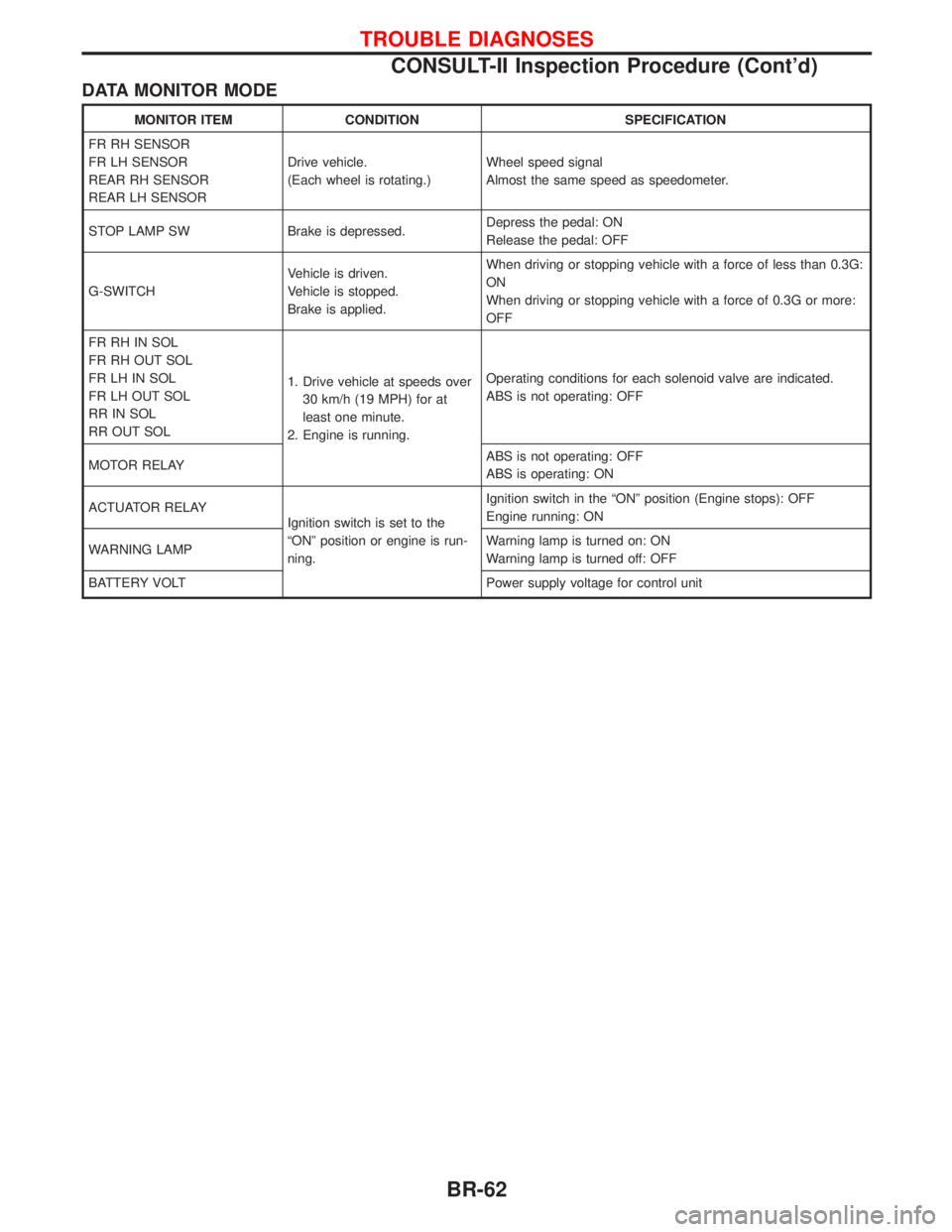
DATA MONITOR MODE
MONITOR ITEM CONDITION SPECIFICATION
FR RH SENSOR
FR LH SENSOR
REAR RH SENSOR
REAR LH SENSORDrive vehicle.
(Each wheel is rotating.)Wheel speed signal
Almost the same speed as speedometer.
STOP LAMP SW Brake is depressed.Depress the pedal: ON
Release the pedal: OFF
G-SWITCHVehicle is driven.
Vehicle is stopped.
Brake is applied.When driving or stopping vehicle with a force of less than 0.3G:
ON
When driving or stopping vehicle with a force of 0.3G or more:
OFF
FR RH IN SOL
FR RH OUT SOL
FR LH IN SOL
FR LH OUT SOL
RR IN SOL
RR OUT SOL1. Drive vehicle at speeds over
30 km/h (19 MPH) for at
least one minute.
2. Engine is running.Operating conditions for each solenoid valve are indicated.
ABS is not operating: OFF
MOTOR RELAYABS is not operating: OFF
ABS is operating: ON
ACTUATOR RELAY
Ignition switch is set to the
ªONº position or engine is run-
ning.Ignition switch in the ªONº position (Engine stops): OFF
Engine running: ON
WARNING LAMPWarning lamp is turned on: ON
Warning lamp is turned off: OFF
BATTERY VOLT Power supply voltage for control unit
TROUBLE DIAGNOSES
CONSULT-II Inspection Procedure (Cont'd)
BR-62
Page 384 of 1767
Fuel Injection Timing Control System
DESCRIPTION
The target fuel injection timing in accordance with the engine speed and the fuel injection amount are recorded
as a map in the ECM beforehand. The ECM and the injection pump control unit exchange signals and per-
form feedback control for optimum injection timing in accordance with the map.
Air Conditioning Cut Control
DESCRIPTION
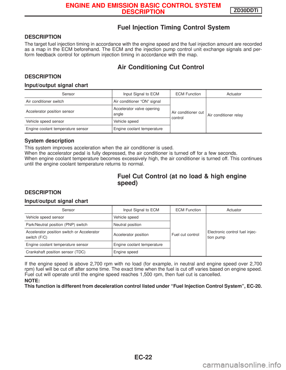
Input/output signal chart
Sensor Input Signal to ECM ECM Function Actuator
Air conditioner switch Air conditioner ªONº signal
Air conditioner cut
controlAir conditioner relay Accelerator position sensorAccelerator valve opening
angle
Vehicle speed sensor Vehicle speed
Engine coolant temperature sensor Engine coolant temperature
System description
This system improves acceleration when the air conditioner is used.
When the accelerator pedal is fully depressed, the air conditioner is turned off for a few seconds.
When engine coolant temperature becomes excessively high, the air conditioner is turned off. This continues
until the engine coolant temperature returns to normal.
Fuel Cut Control (at no load & high engine
speed)
DESCRIPTION
Input/output signal chart
Sensor Input Signal to ECM ECM Function Actuator
Vehicle speed sensor Vehicle speed
Fuel cut controlElectronic control fuel injec-
tion pump Park/Neutral position (PNP) switch Neutral position
Accelerator position switch or Accelerator
switch (F/C)Accelerator position
Engine coolant temperature sensor Engine coolant temperature
Crankshaft position sensor (TDC) Engine speed
If the engine speed is above 2,700 rpm with no load (for example, in neutral and engine speed over 2,700
rpm) fuel will be cut off after some time. The exact time when the fuel is cut off varies based on engine speed.
Fuel cut will operate until the engine speed reaches 1,500 rpm, then fuel cut is cancelled.
NOTE:
This function is different from deceleration control listed under ªFuel Injection Control Systemº, EC-20.
ENGINE AND EMISSION BASIC CONTROL SYSTEM
DESCRIPTIONZD30DDTi
EC-22
Page 425 of 1767
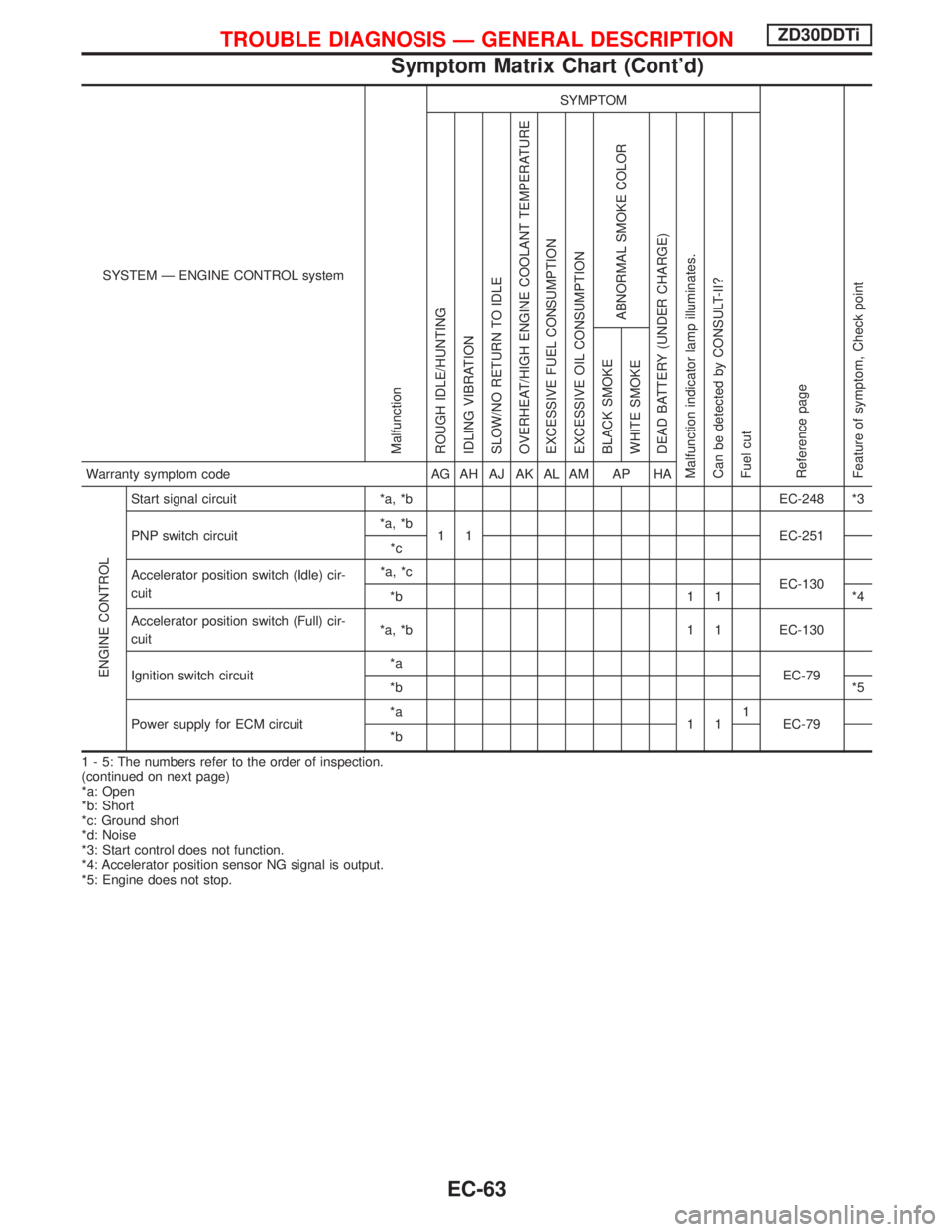
SYSTEM Ð ENGINE CONTROL system
Malfunction
SYMPTOM
Reference page
Feature of symptom, Check pointROUGH IDLE/HUNTING
IDLING VIBRATION
SLOW/NO RETURN TO IDLE
OVERHEAT/HIGH ENGINE COOLANT TEMPERATURE
EXCESSIVE FUEL CONSUMPTION
EXCESSIVE OIL CONSUMPTION
ABNORMAL SMOKE COLOR
DEAD BATTERY (UNDER CHARGE)
Malfunction indicator lamp illuminates.
Can be detected by CONSULT-II?
Fuel cutBLACK SMOKE
WHITE SMOKEWarranty symptom code AG AH AJ AK AL AM AP HA
ENGINE CONTROL
Start signal circuit *a, *b EC-248 *3
PNP switch circuit*a, *b
1 1 EC-251
*c
Accelerator position switch (Idle) cir-
cuit*a, *c
EC-130
*b 1 1 *4
Accelerator position switch (Full) cir-
cuit*a, *b 1 1 EC-130
Ignition switch circuit*a
EC-79
*b*5
Power supply for ECM circuit*a
111
EC-79
*b
1 - 5: The numbers refer to the order of inspection.
(continued on next page)
*a: Open
*b: Short
*c: Ground short
*d: Noise
*3: Start control does not function.
*4: Accelerator position sensor NG signal is output.
*5: Engine does not stop.
TROUBLE DIAGNOSIS Ð GENERAL DESCRIPTIONZD30DDTi
Symptom Matrix Chart (Cont'd)
EC-63
Page 428 of 1767
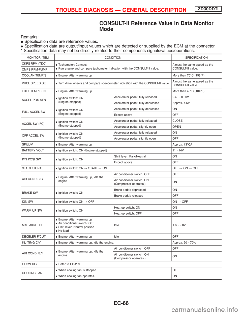
CONSULT-II Reference Value in Data Monitor
Mode
Remarks:
ISpecification data are reference values.
ISpecification data are output/input values which are detected or supplied by the ECM at the connector.
* Specification data may not be directly related to their components signals/values/operations.
MONITOR ITEM CONDITION SPECIFICATION
CKPS×RPM (TDC)
ITachometer: Connect
IRun engine and compare tachometer indication with the CONSULT-II value.Almost the same speed as the
CONSULT-II value.
CMPS×RPM-PUMP
COOLAN TEMP/SIEngine: After warming up More than 70ÉC (158ÉF)
VHCL SPEED SEITurn drive wheels and compare speedometer indication with the CONSULT-II valueAlmost the same speed as the
CONSULT-II value
FUEL TEMP SENIEngine: After warming up More than 40ÉC (104ÉF)
ACCEL POS SENIIgnition switch: ON
(Engine stopped)Accelerator pedal: fully released 0.40 - 0.60V
Accelerator pedal: fully depressed Approx. 4.5V
FULL ACCEL SWIIgnition switch: ON
(Engine stopped)Accelerator pedal: fully depressed ON
Except above OFF
ACCEL SW (FC)IIgnition switch: ON
(Engine stopped)Accelerator pedal: fully released CLOSE
Accelerator pedal: slightly open OPEN
OFF ACCEL SWIIgnition switch: ON
(Engine stopped)Accelerator pedal: fully released ON
Accelerator pedal: slightly open OFF
SPILL/VIEngine: After warming up Approx. 13ÉCA
BATTERY VOLTIIgnition switch: ON (Engine stopped) 11 - 14V
P/N POSI SWIIgnition switch: ONShift lever: Park/Neutral ON
Except above OFF
START SIGNALIIgnition switch: ON,START,ON OFF,ON,OFF
AIR COND SIGIEngine: After warming up, idle the
engineAir conditioner switch: OFF OFF
Air conditioner switch: ON
(Compressor operates.)ON
BRAKE SWIIgnition switch: ONBrake pedal: depressed ON
Brake pedal: released OFF
IGN SWIIgnition switch: ON,OFF ON,OFF
WARM UP SWIIgnition switch: ONHeat up switch: ON ON
Heat up switch: OFF OFF
MAS AIR/FL SEIEngine: After warming up
IAir conditioner switch: OFF
IShift lever: Neutral position
INo-loadIdle 1.6 - 2.0V
DECELER F/CUTIEngine: After warming up Idle OFF
INJ TIMG C/VIEngine: After warming up, idle the engine. Approx. 50 - 70%
AIR COND RLYIEngine: After warming up, idle the
engineAir conditioner switch: OFF OFF
Air conditioner switch: ON
(Compressor operates.)ON
GLOW RLYIRefer to EC-239.
COOLING FANIWhen cooling fan is stopped. OFF
IWhen cooling fan operates. ON
TROUBLE DIAGNOSIS Ð GENERAL DESCRIPTIONZD30DDTi
EC-66
Page 432 of 1767
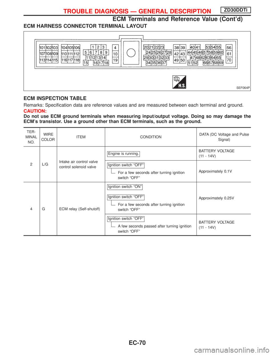
ECM HARNESS CONNECTOR TERMINAL LAYOUT
ECM INSPECTION TABLE
Remarks: Specification data are reference values and are measured between each terminal and ground.
CAUTION:
Do not use ECM ground terminals when measuring input/output voltage. Doing so may damage the
ECM's transistor. Use a ground other than ECM terminals, such as the ground.
TER-
MINAL
NO.WIRE
COLORITEM CONDITIONDATA (DC Voltage and Pulse
Signal)
2 L/GIntake air control valve
control solenoid valveEngine is running.
BATTERY VOLTAGE
(11 - 14V)
Ignition switch ªOFFº
For a few seconds after turning ignition
switch ªOFFºApproximately 0.1V
4 G ECM relay (Self-shutoff)Ignition switch ªONº
Ignition switch ªOFFº
For a few seconds after turning ignition
switch ªOFFºApproximately 0.25V
Ignition switch ªOFFº
A few seconds passed after turning ignition
switch ªOFFºBATTERY VOLTAGE
(11 - 14V)
SEF064P
TROUBLE DIAGNOSIS Ð GENERAL DESCRIPTIONZD30DDTi
ECM Terminals and Reference Value (Cont'd)
EC-70