2002 NISSAN TERRANO turn signal
[x] Cancel search: turn signalPage 69 of 1767
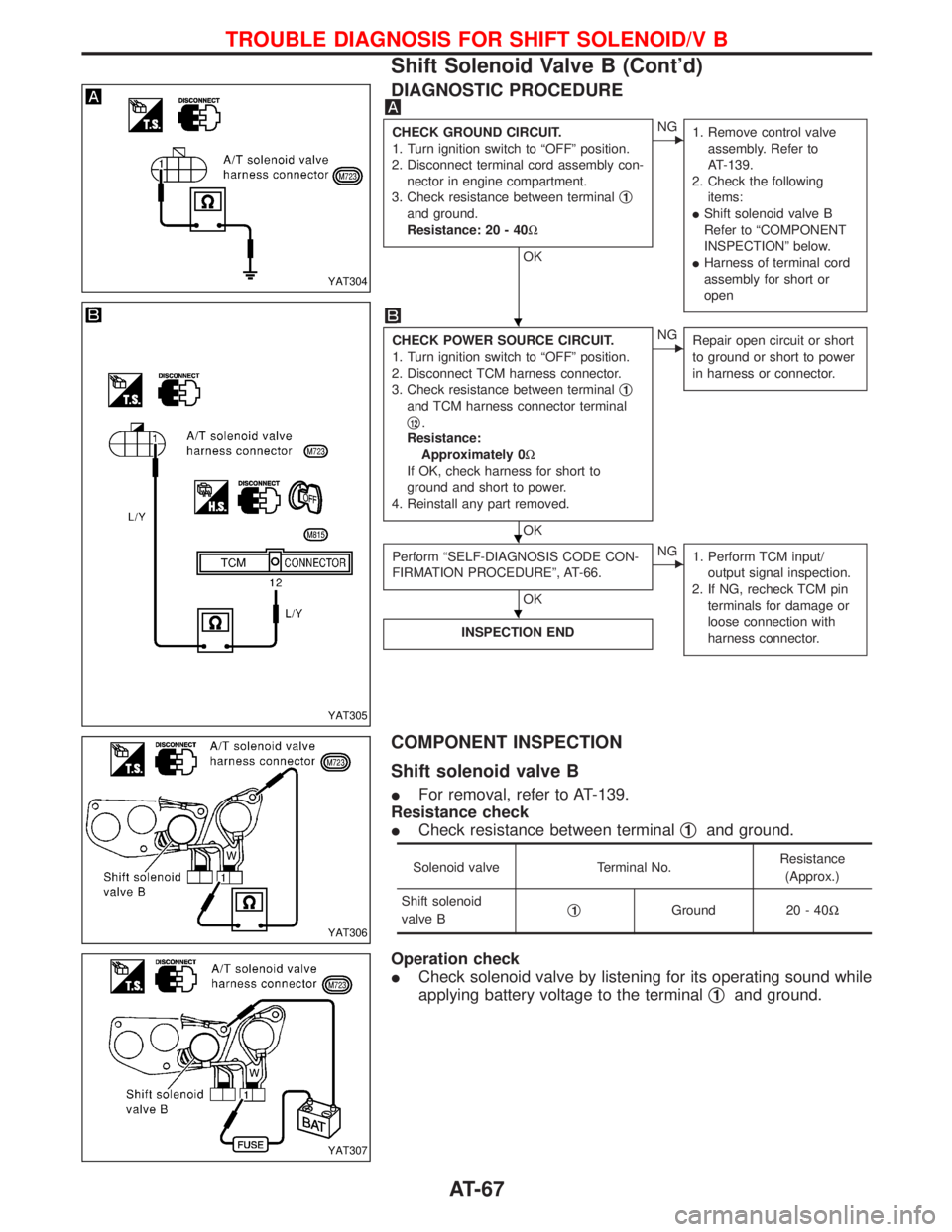
DIAGNOSTIC PROCEDURE
CHECK GROUND CIRCUIT.
1. Turn ignition switch to ªOFFº position.
2. Disconnect terminal cord assembly con-
nector in engine compartment.
3. Check resistance between terminalq
1
and ground.
Resistance: 20 - 40W
OK
ENG
1. Remove control valve
assembly. Refer to
AT-139.
2. Check the following
items:
IShift solenoid valve B
Refer to ªCOMPONENT
INSPECTIONº below.
IHarness of terminal cord
assembly for short or
open
CHECK POWER SOURCE CIRCUIT.
1. Turn ignition switch to ªOFFº position.
2. Disconnect TCM harness connector.
3. Check resistance between terminalq
1
and TCM harness connector terminal
q
12.
Resistance:
Approximately 0W
If OK, check harness for short to
ground and short to power.
4. Reinstall any part removed.
OK
ENG
Repair open circuit or short
to ground or short to power
in harness or connector.
Perform ªSELF-DIAGNOSIS CODE CON-
FIRMATION PROCEDUREº, AT-66.
OK
ENG
1. Perform TCM input/
output signal inspection.
2. If NG, recheck TCM pin
terminals for damage or
loose connection with
harness connector.
INSPECTION END
COMPONENT INSPECTION
Shift solenoid valve B
IFor removal, refer to AT-139.
Resistance check
ICheck resistance between terminalq
1and ground.
Solenoid valve Terminal No.Resistance
(Approx.)
Shift solenoid
valve Bq
1Ground 20 - 40W
Operation check
ICheck solenoid valve by listening for its operating sound while
applying battery voltage to the terminalq
1and ground.
YAT304
YAT305
YAT306
YAT307
H
H
H
TROUBLE DIAGNOSIS FOR SHIFT SOLENOID/V B
Shift Solenoid Valve B (Cont'd)
AT-67
Page 72 of 1767
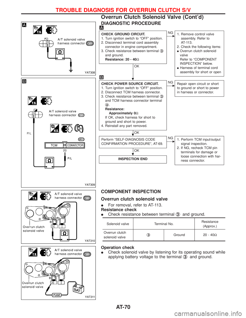
DIAGNOSTIC PROCEDURE
CHECK GROUND CIRCUIT.
1. Turn ignition switch to ªOFFº position.
2. Disconnect terminal cord assembly
connector in engine compartment.
3. Check resistance between terminalq
3
and ground.
Resistance: 20 - 40W
OK
ENG
1. Remove control valve
assembly. Refer to
AT-113.
2. Check the following items:
IOverrun clutch solenoid
valve
Refer to ªCOMPONENT
INSPECTIONº below.
IHarness of terminal cord
assembly for short or open
CHECK POWER SOURCE CIRCUIT.
1. Turn ignition switch to ªOFFº position.
2. Disconnect TCM harness connector.
3. Check resistance between terminalq
3
and TCM harness connector terminal
q
20.
Resistance:
Approximately 0W
If OK, check harness for short to
ground and short to power.
4. Reinstall any part removed.
OK
ENG
Repair open circuit or short
to ground or short to power
in harness or connector.
Perform ªSELF-DIAGNOSIS CODE
CONFIRMATION PROCEDUREº, AT-69.
OK
ENG
1. Perform TCM input/output
signal inspection.
2. If NG, recheck TCM pin
terminals for damage or
loose connection with har-
ness connector.
INSPECTION END
COMPONENT INSPECTION
Overrun clutch solenoid valve
IFor removal, refer to AT-113.
Resistance check
ICheck resistance between terminalq
3and ground.
Solenoid valve Terminal No.Resistance
(Approx.)
Overrun clutch
solenoid valveq
3Ground 20 - 40W
Operation check
ICheck solenoid valve by listening for its operating sound while
applying battery voltage to the terminalq
3and ground.
YAT308
YAT309
YAT310
YAT311
H
H
H
TROUBLE DIAGNOSIS FOR OVERRUN CLUTCH S/V
Overrun Clutch Solenoid Valve (Cont'd)
AT-70
Page 75 of 1767
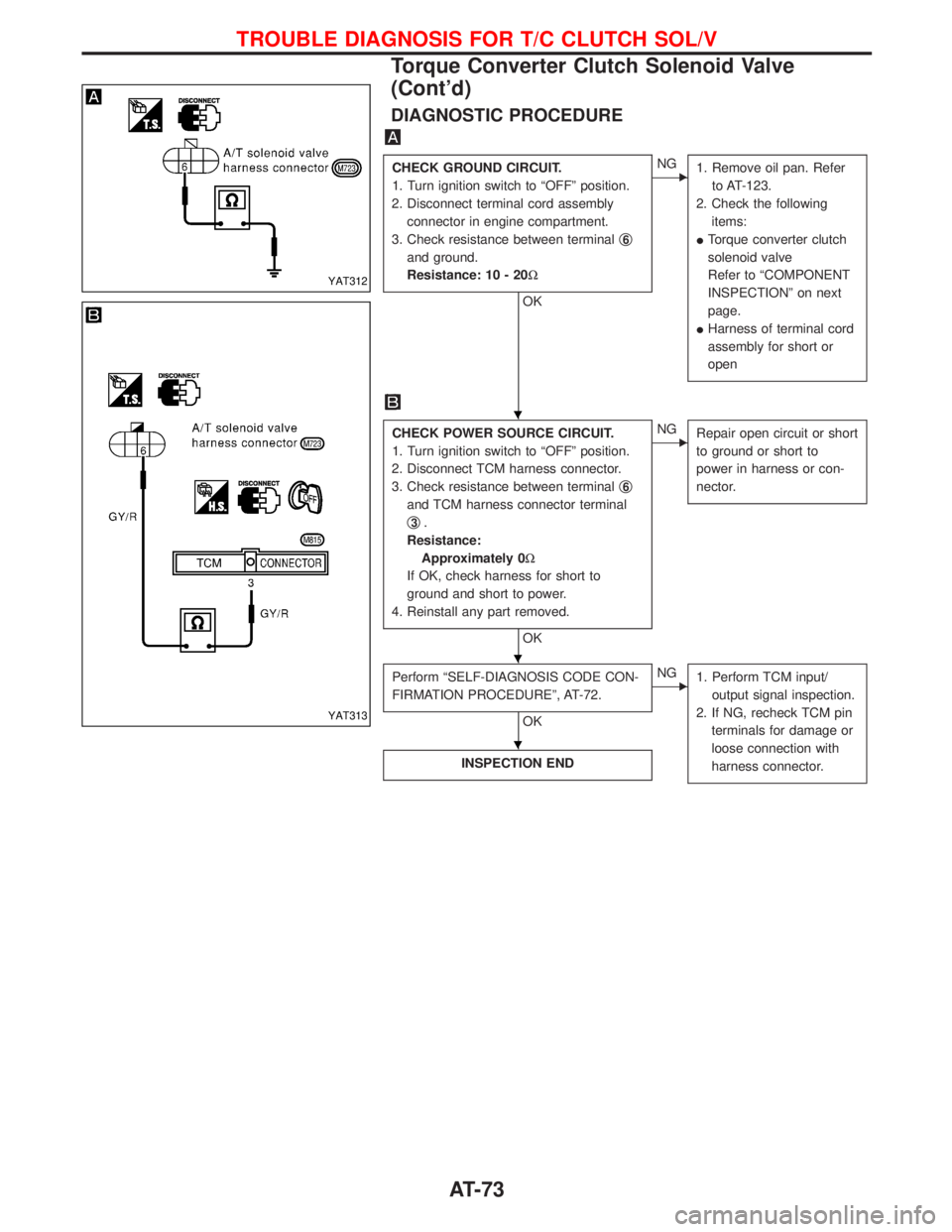
DIAGNOSTIC PROCEDURE
CHECK GROUND CIRCUIT.
1. Turn ignition switch to ªOFFº position.
2. Disconnect terminal cord assembly
connector in engine compartment.
3. Check resistance between terminalq
6
and ground.
Resistance: 10 - 20W
OK
ENG
1. Remove oil pan. Refer
to AT-123.
2. Check the following
items:
ITorque converter clutch
solenoid valve
Refer to ªCOMPONENT
INSPECTIONº on next
page.
IHarness of terminal cord
assembly for short or
open
CHECK POWER SOURCE CIRCUIT.
1. Turn ignition switch to ªOFFº position.
2. Disconnect TCM harness connector.
3. Check resistance between terminalq
6
and TCM harness connector terminal
q
3.
Resistance:
Approximately 0W
If OK, check harness for short to
ground and short to power.
4. Reinstall any part removed.
OK
ENG
Repair open circuit or short
to ground or short to
power in harness or con-
nector.
Perform ªSELF-DIAGNOSIS CODE CON-
FIRMATION PROCEDUREº, AT-72.
OK
ENG
1. Perform TCM input/
output signal inspection.
2. If NG, recheck TCM pin
terminals for damage or
loose connection with
harness connector.
INSPECTION END
YAT312
YAT313
H
H
H
TROUBLE DIAGNOSIS FOR T/C CLUTCH SOL/V
Torque Converter Clutch Solenoid Valve
(Cont'd)
AT-73
Page 87 of 1767
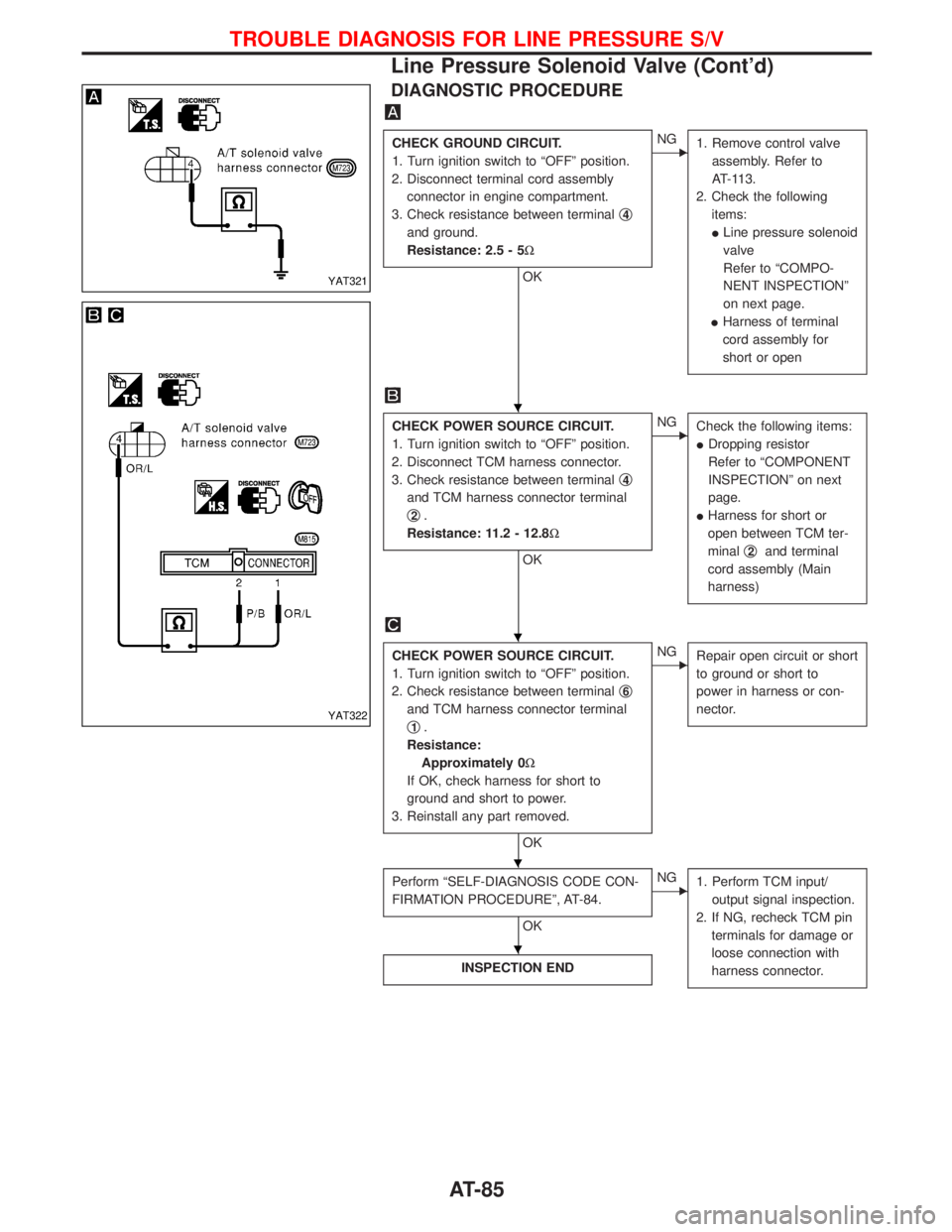
DIAGNOSTIC PROCEDURE
CHECK GROUND CIRCUIT.
1. Turn ignition switch to ªOFFº position.
2. Disconnect terminal cord assembly
connector in engine compartment.
3. Check resistance between terminalq
4
and ground.
Resistance: 2.5 - 5W
OK
ENG
1. Remove control valve
assembly. Refer to
AT-113.
2. Check the following
items:
ILine pressure solenoid
valve
Refer to ªCOMPO-
NENT INSPECTIONº
on next page.
IHarness of terminal
cord assembly for
short or open
CHECK POWER SOURCE CIRCUIT.
1. Turn ignition switch to ªOFFº position.
2. Disconnect TCM harness connector.
3. Check resistance between terminalq
4
and TCM harness connector terminal
q
2.
Resistance: 11.2 - 12.8W
OK
ENG
Check the following items:
IDropping resistor
Refer to ªCOMPONENT
INSPECTIONº on next
page.
IHarness for short or
open between TCM ter-
minalq
2and terminal
cord assembly (Main
harness)
CHECK POWER SOURCE CIRCUIT.
1. Turn ignition switch to ªOFFº position.
2. Check resistance between terminalq
6
and TCM harness connector terminal
q
1.
Resistance:
Approximately 0W
If OK, check harness for short to
ground and short to power.
3. Reinstall any part removed.
OK
ENG
Repair open circuit or short
to ground or short to
power in harness or con-
nector.
Perform ªSELF-DIAGNOSIS CODE CON-
FIRMATION PROCEDUREº, AT-84.
OK
ENG
1. Perform TCM input/
output signal inspection.
2. If NG, recheck TCM pin
terminals for damage or
loose connection with
harness connector.
INSPECTION END
YAT321
YAT322
H
H
H
H
TROUBLE DIAGNOSIS FOR LINE PRESSURE S/V
Line Pressure Solenoid Valve (Cont'd)
AT-85
Page 91 of 1767
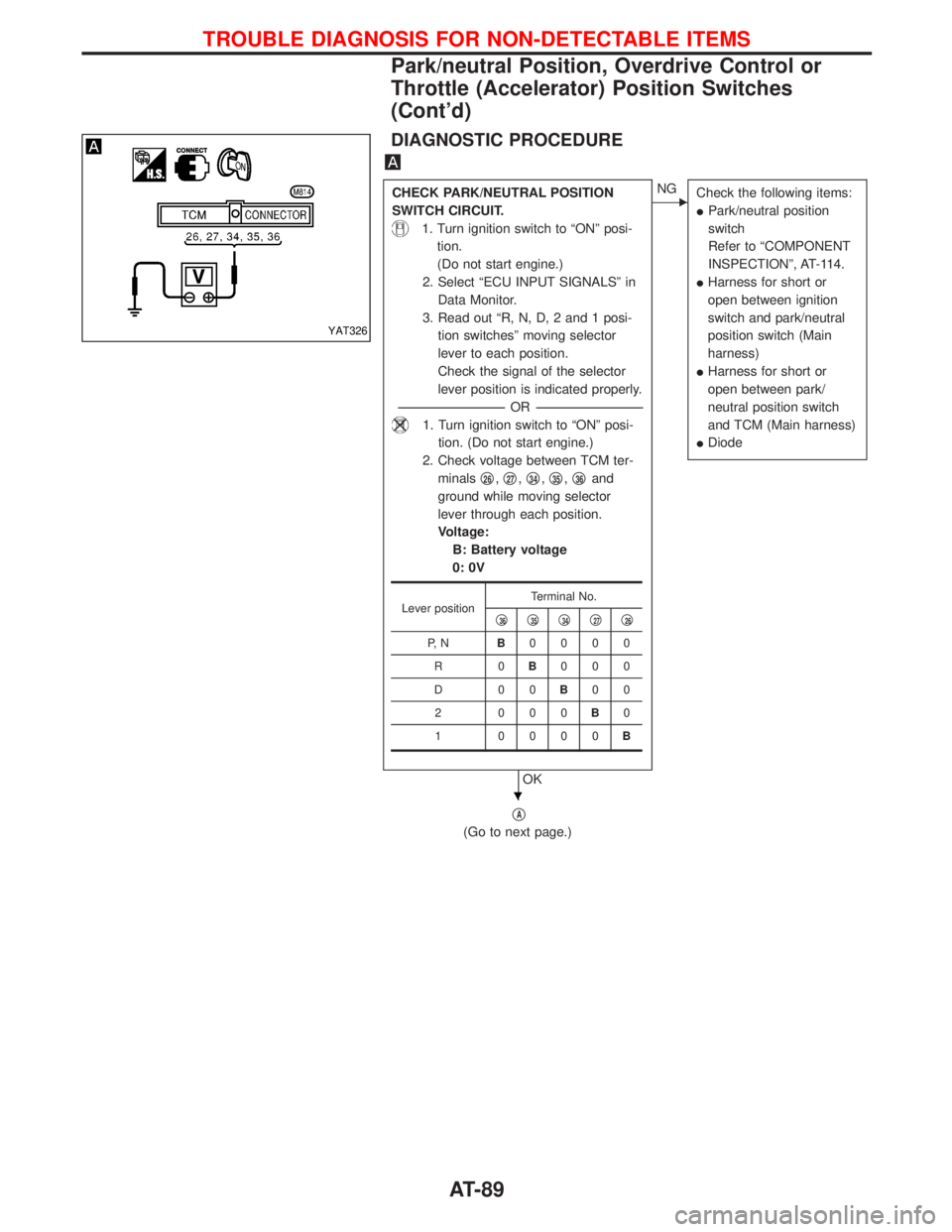
DIAGNOSTIC PROCEDURE
CHECK PARK/NEUTRAL POSITION
SWITCH CIRCUIT.
1. Turn ignition switch to ªONº posi-
tion.
(Do not start engine.)
2. Select ªECU INPUT SIGNALSº in
Data Monitor.
3. Read out ªR, N, D, 2 and 1 posi-
tion switchesº moving selector
lever to each position.
Check the signal of the selector
lever position is indicated properly.
-----------------------------------------------------------------------------------------------------------------------OR -----------------------------------------------------------------------------------------------------------------------
1. Turn ignition switch to ªONº posi-
tion. (Do not start engine.)
2. Check voltage between TCM ter-
minalsq
26,q27,q34,q35,q36and
ground while moving selector
lever through each position.
Voltage:
B: Battery voltage
0: 0V
OK
ENG
Check the following items:
IPark/neutral position
switch
Refer to ªCOMPONENT
INSPECTIONº, AT-114.
IHarness for short or
open between ignition
switch and park/neutral
position switch (Main
harness)
IHarness for short or
open between park/
neutral position switch
and TCM (Main harness)
IDiode
qA
(Go to next page.)
Lever positionTerminal No.
q36q35q34q27q26
P, NB0000
R0B000
D00B00
2 000B0
1 0000B
YAT326
H
TROUBLE DIAGNOSIS FOR NON-DETECTABLE ITEMS
Park/neutral Position, Overdrive Control or
Throttle (Accelerator) Position Switches
(Cont'd)
AT-89
Page 92 of 1767
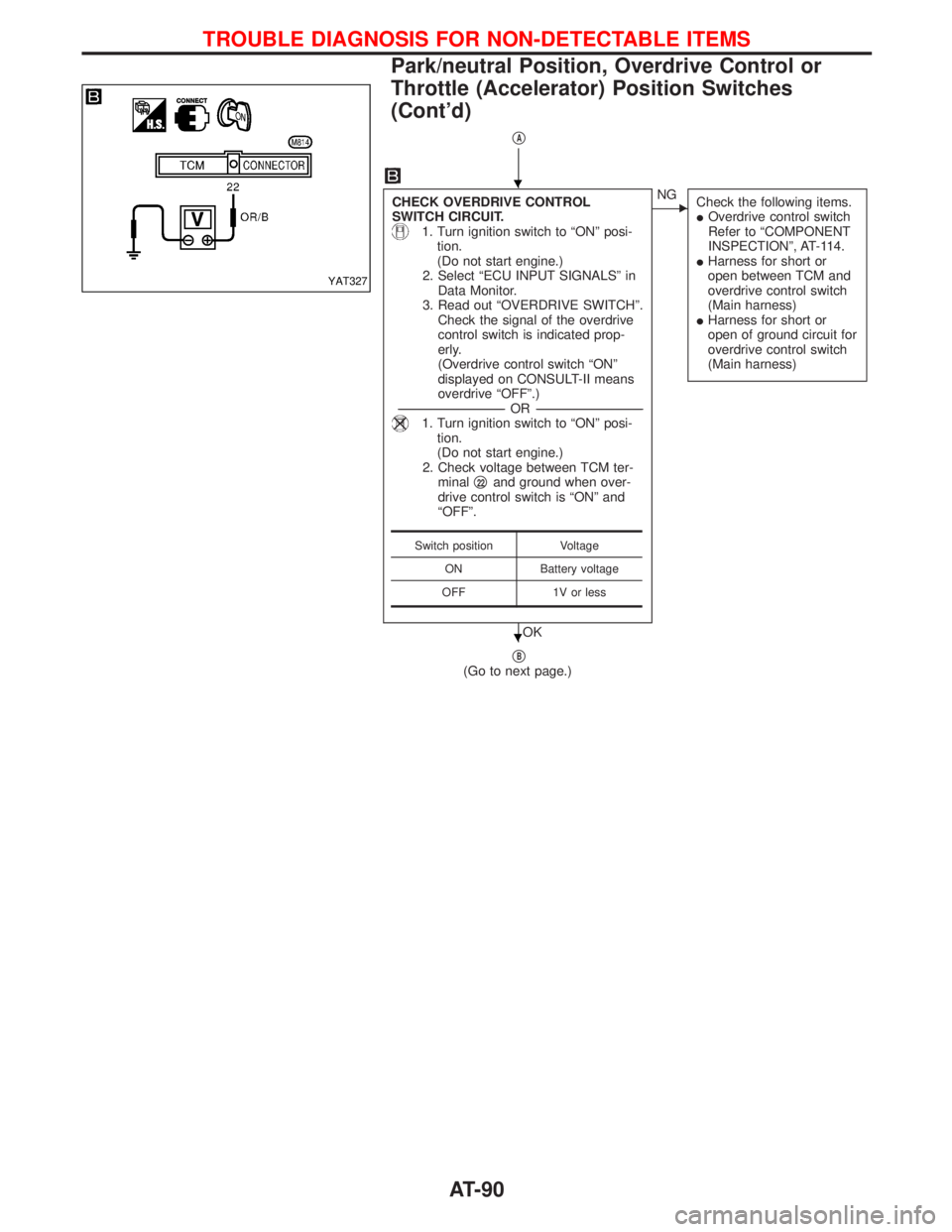
qA
CHECK OVERDRIVE CONTROL
SWITCH CIRCUIT.
1. Turn ignition switch to ªONº posi-
tion.
(Do not start engine.)
2. Select ªECU INPUT SIGNALSº in
Data Monitor.
3. Read out ªOVERDRIVE SWITCHº.
Check the signal of the overdrive
control switch is indicated prop-
erly.
(Overdrive control switch ªONº
displayed on CONSULT-II means
overdrive ªOFFº.)
-----------------------------------------------------------------------------------------------------------------------OR -----------------------------------------------------------------------------------------------------------------------
1. Turn ignition switch to ªONº posi-
tion.
(Do not start engine.)
2. Check voltage between TCM ter-
minalq
22and ground when over-
drive control switch is ªONº and
ªOFFº.
OK
ENG
Check the following items.
IOverdrive control switch
Refer to ªCOMPONENT
INSPECTIONº, AT-114.
IHarness for short or
open between TCM and
overdrive control switch
(Main harness)
IHarness for short or
open of ground circuit for
overdrive control switch
(Main harness)
qB(Go to next page.)
Switch position Voltage
ON Battery voltage
OFF 1V or less
YAT327
H
H
TROUBLE DIAGNOSIS FOR NON-DETECTABLE ITEMS
Park/neutral Position, Overdrive Control or
Throttle (Accelerator) Position Switches
(Cont'd)
AT-90
Page 93 of 1767
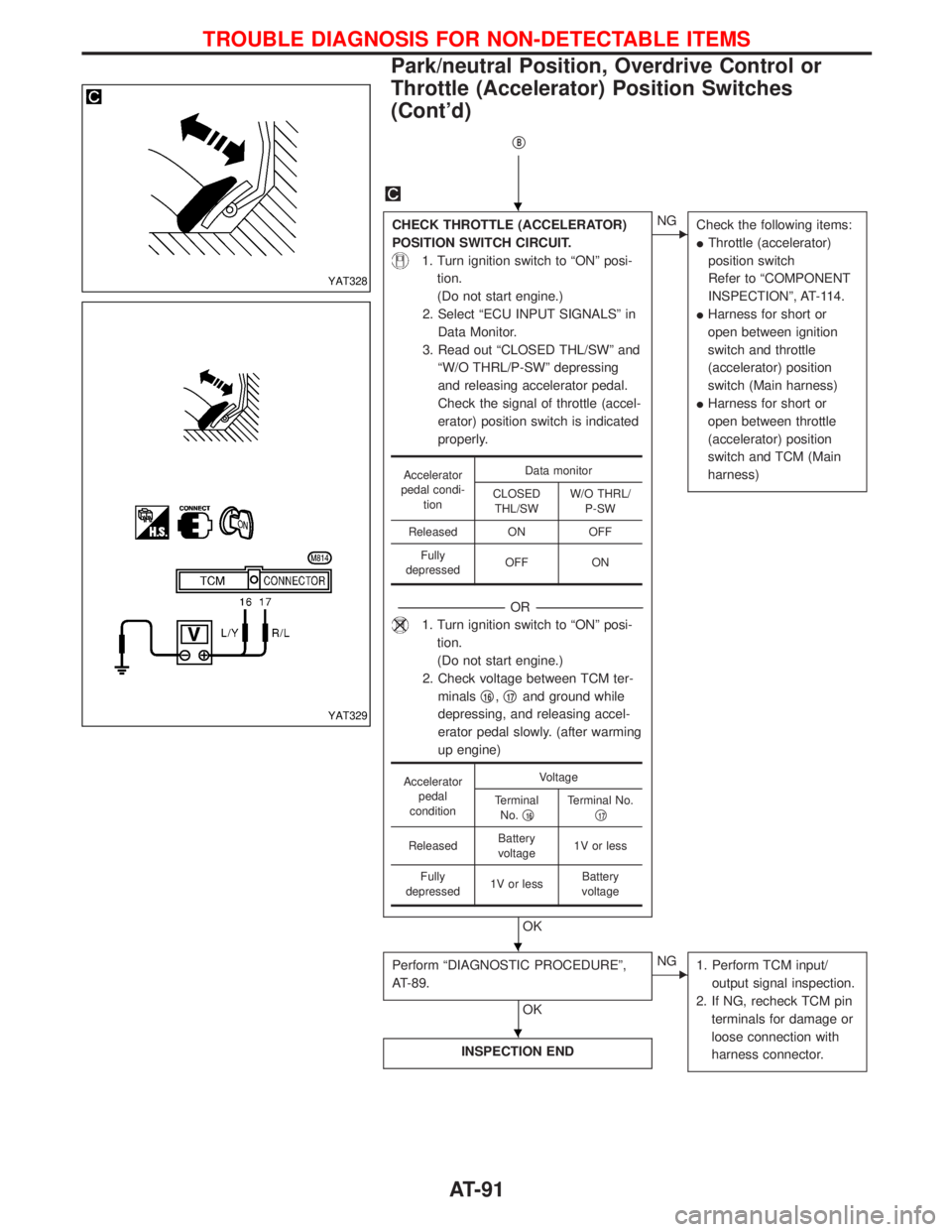
qB
CHECK THROTTLE (ACCELERATOR)
POSITION SWITCH CIRCUIT.
1. Turn ignition switch to ªONº posi-
tion.
(Do not start engine.)
2. Select ªECU INPUT SIGNALSº in
Data Monitor.
3. Read out ªCLOSED THL/SWº and
ªW/O THRL/P-SWº depressing
and releasing accelerator pedal.
Check the signal of throttle (accel-
erator) position switch is indicated
properly.
-----------------------------------------------------------------------------------------------------------------------OR -----------------------------------------------------------------------------------------------------------------------
1. Turn ignition switch to ªONº posi-
tion.
(Do not start engine.)
2. Check voltage between TCM ter-
minalsq
16,q17and ground while
depressing, and releasing accel-
erator pedal slowly. (after warming
up engine)
OK
ENG
Check the following items:
IThrottle (accelerator)
position switch
Refer to ªCOMPONENT
INSPECTIONº, AT-114.
IHarness for short or
open between ignition
switch and throttle
(accelerator) position
switch (Main harness)
IHarness for short or
open between throttle
(accelerator) position
switch and TCM (Main
harness)
Perform ªDIAGNOSTIC PROCEDUREº,
AT-89.
OK
ENG
1. Perform TCM input/
output signal inspection.
2. If NG, recheck TCM pin
terminals for damage or
loose connection with
harness connector.
INSPECTION END
Accelerator
pedal condi-
tionData monitor
CLOSED
THL/SWW/O THRL/
P-SW
Released ON OFF
Fully
depressedOFF ON
Accelerator
pedal
conditionVoltage
Terminal
No.q
16Terminal No.
q17
ReleasedBattery
voltage1V or less
Fully
depressed1V or lessBattery
voltage
YAT328
YAT329
H
H
H
TROUBLE DIAGNOSIS FOR NON-DETECTABLE ITEMS
Park/neutral Position, Overdrive Control or
Throttle (Accelerator) Position Switches
(Cont'd)
AT-91
Page 96 of 1767
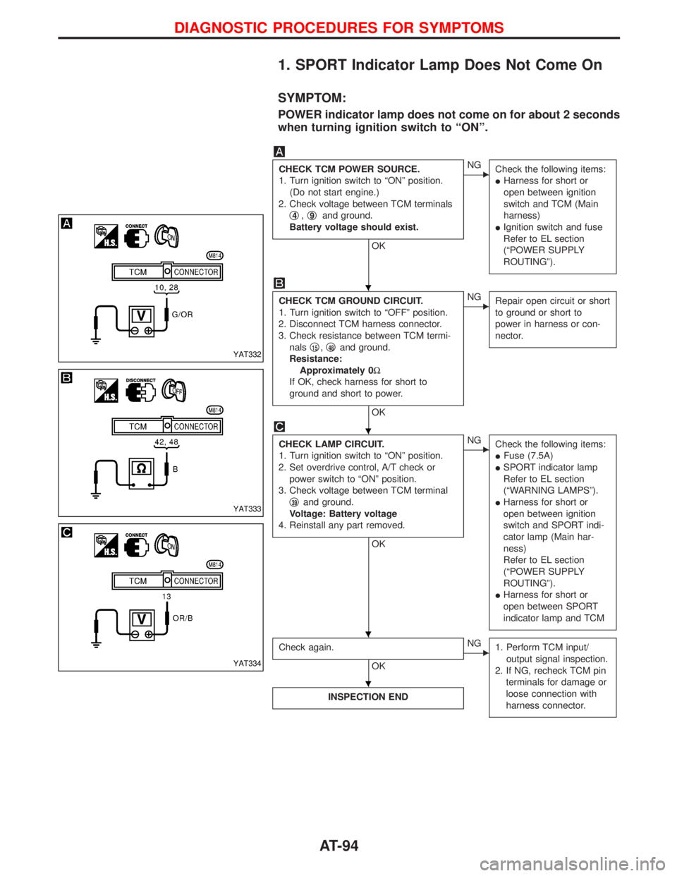
1. SPORT Indicator Lamp Does Not Come On
SYMPTOM:
POWER indicator lamp does not come on for about 2 seconds
when turning ignition switch to ªONº.
CHECK TCM POWER SOURCE.
1. Turn ignition switch to ªONº position.
(Do not start engine.)
2. Check voltage between TCM terminals
q
4,q9and ground.
Battery voltage should exist.
OK
ENG
Check the following items:
IHarness for short or
open between ignition
switch and TCM (Main
harness)
IIgnition switch and fuse
Refer to EL section
(ªPOWER SUPPLY
ROUTINGº).
CHECK TCM GROUND CIRCUIT.
1. Turn ignition switch to ªOFFº position.
2. Disconnect TCM harness connector.
3. Check resistance between TCM termi-
nalsq
15,q48and ground.
Resistance:
Approximately 0W
If OK, check harness for short to
ground and short to power.
OK
ENG
Repair open circuit or short
to ground or short to
power in harness or con-
nector.
CHECK LAMP CIRCUIT.
1. Turn ignition switch to ªONº position.
2. Set overdrive control, A/T check or
power switch to ªONº position.
3. Check voltage between TCM terminal
q
39and ground.
Voltage: Battery voltage
4. Reinstall any part removed.
OK
ENG
Check the following items:
IFuse (7.5A)
ISPORT indicator lamp
Refer to EL section
(ªWARNING LAMPSº).
IHarness for short or
open between ignition
switch and SPORT indi-
cator lamp (Main har-
ness)
Refer to EL section
(ªPOWER SUPPLY
ROUTINGº).
IHarness for short or
open between SPORT
indicator lamp and TCM
Check again.
OK
ENG
1. Perform TCM input/
output signal inspection.
2. If NG, recheck TCM pin
terminals for damage or
loose connection with
harness connector.
INSPECTION END
YAT332
YAT333
YAT334
H
H
H H
H
DIAGNOSTIC PROCEDURES FOR SYMPTOMS
AT-94