Page 436 of 1767
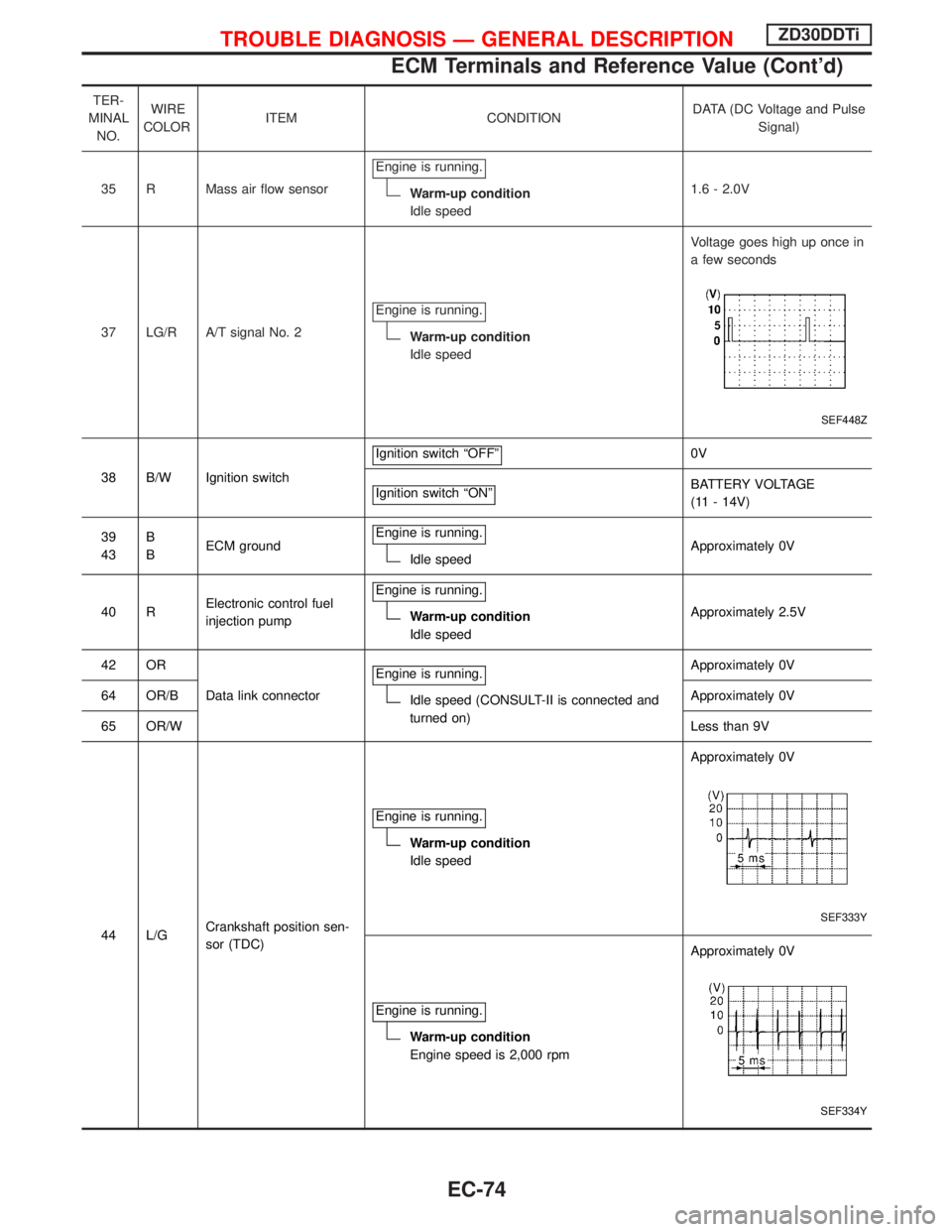
TER-
MINAL
NO.WIRE
COLORITEM CONDITIONDATA (DC Voltage and Pulse
Signal)
35 R Mass air flow sensorEngine is running.
Warm-up condition
Idle speed1.6 - 2.0V
37 LG/R A/T signal No. 2Engine is running.
Warm-up condition
Idle speedVoltage goes high up once in
a few seconds
SEF448Z
38 B/W Ignition switchIgnition switch ªOFFº
0V
Ignition switch ªONº
BATTERY VOLTAGE
(11 - 14V)
39
43B
BECM groundEngine is running.
Idle speedApproximately 0V
40 RElectronic control fuel
injection pumpEngine is running.
Warm-up condition
Idle speedApproximately 2.5V
42 OR
Data link connectorEngine is running.
Idle speed (CONSULT-II is connected and
turned on)Approximately 0V
64 OR/BApproximately 0V
65 OR/WLess than 9V
44 L/GCrankshaft position sen-
sor (TDC)Engine is running.
Warm-up condition
Idle speedApproximately 0V
SEF333Y
Engine is running.
Warm-up condition
Engine speed is 2,000 rpmApproximately 0V
SEF334Y
TROUBLE DIAGNOSIS Ð GENERAL DESCRIPTIONZD30DDTi
ECM Terminals and Reference Value (Cont'd)
EC-74
Page 438 of 1767
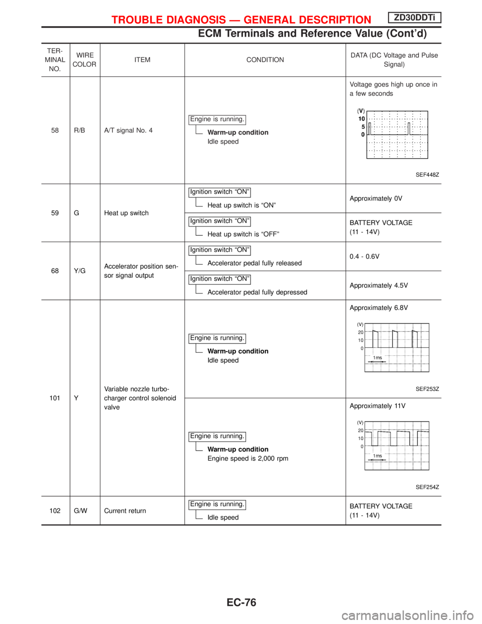
TER-
MINAL
NO.WIRE
COLORITEM CONDITIONDATA (DC Voltage and Pulse
Signal)
58 R/B A/T signal No. 4Engine is running.
Warm-up condition
Idle speedVoltage goes high up once in
a few seconds
SEF448Z
59 G Heat up switchIgnition switch ªONºHeat up switch is ªONºApproximately 0V
Ignition switch ªONº
Heat up switch is ªOFFºBATTERY VOLTAGE
(11 - 14V)
68 Y/GAccelerator position sen-
sor signal outputIgnition switch ªONº
Accelerator pedal fully released0.4 - 0.6V
Ignition switch ªONº
Accelerator pedal fully depressedApproximately 4.5V
101 YVariable nozzle turbo-
charger control solenoid
valveEngine is running.
Warm-up condition
Idle speedApproximately 6.8V
SEF253Z
Engine is running.
Warm-up condition
Engine speed is 2,000 rpmApproximately 11V
SEF254Z
102 G/W Current returnEngine is running.Idle speedBATTERY VOLTAGE
(11 - 14V)
TROUBLE DIAGNOSIS Ð GENERAL DESCRIPTIONZD30DDTi
ECM Terminals and Reference Value (Cont'd)
EC-76
Page 455 of 1767
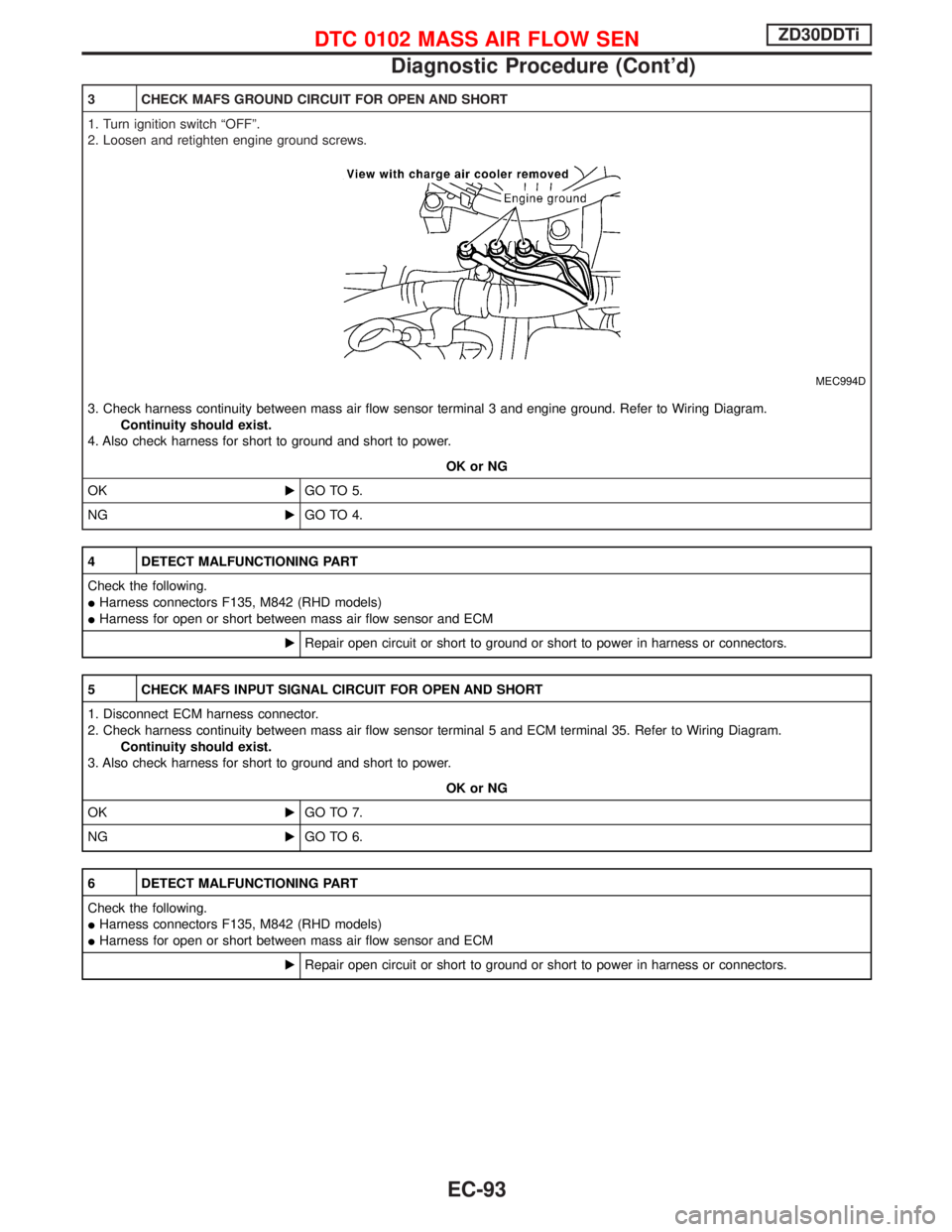
3 CHECK MAFS GROUND CIRCUIT FOR OPEN AND SHORT
1. Turn ignition switch ªOFFº.
2. Loosen and retighten engine ground screws.
MEC994D
3. Check harness continuity between mass air flow sensor terminal 3 and engine ground. Refer to Wiring Diagram.
Continuity should exist.
4. Also check harness for short to ground and short to power.
OK or NG
OKEGO TO 5.
NGEGO TO 4.
4 DETECT MALFUNCTIONING PART
Check the following.
IHarness connectors F135, M842 (RHD models)
IHarness for open or short between mass air flow sensor and ECM
ERepair open circuit or short to ground or short to power in harness or connectors.
5 CHECK MAFS INPUT SIGNAL CIRCUIT FOR OPEN AND SHORT
1. Disconnect ECM harness connector.
2. Check harness continuity between mass air flow sensor terminal 5 and ECM terminal 35. Refer to Wiring Diagram.
Continuity should exist.
3. Also check harness for short to ground and short to power.
OK or NG
OKEGO TO 7.
NGEGO TO 6.
6 DETECT MALFUNCTIONING PART
Check the following.
IHarness connectors F135, M842 (RHD models)
IHarness for open or short between mass air flow sensor and ECM
ERepair open circuit or short to ground or short to power in harness or connectors.
DTC 0102 MASS AIR FLOW SENZD30DDTi
Diagnostic Procedure (Cont'd)
EC-93
Page 457 of 1767
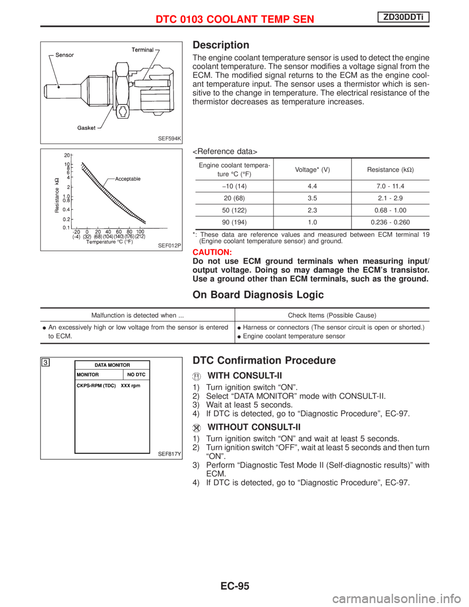
Description
The engine coolant temperature sensor is used to detect the engine
coolant temperature. The sensor modifies a voltage signal from the
ECM. The modified signal returns to the ECM as the engine cool-
ant temperature input. The sensor uses a thermistor which is sen-
sitive to the change in temperature. The electrical resistance of the
thermistor decreases as temperature increases.
Engine coolant tempera-
ture ÉC (ÉF)Voltage* (V) Resistance (kW)
þ10 (14) 4.4 7.0 - 11.4
20 (68) 3.5 2.1 - 2.9
50 (122) 2.3 0.68 - 1.00
90 (194) 1.0 0.236 - 0.260
*: These data are reference values and measured between ECM terminal 19
(Engine coolant temperature sensor) and ground.
CAUTION:
Do not use ECM ground terminals when measuring input/
output voltage. Doing so may damage the ECM's transistor.
Use a ground other than ECM terminals, such as the ground.
On Board Diagnosis Logic
Malfunction is detected when ... Check Items (Possible Cause)
IAn excessively high or low voltage from the sensor is entered
to ECM.IHarness or connectors (The sensor circuit is open or shorted.)
IEngine coolant temperature sensor
DTC Confirmation Procedure
WITH CONSULT-II
1) Turn ignition switch ªONº.
2) Select ªDATA MONITORº mode with CONSULT-II.
3) Wait at least 5 seconds.
4) If DTC is detected, go to ªDiagnostic Procedureº, EC-97.
WITHOUT CONSULT-II
1) Turn ignition switch ªONº and wait at least 5 seconds.
2) Turn ignition switch ªOFFº, wait at least 5 seconds and then turn
ªONº.
3) Perform ªDiagnostic Test Mode II (Self-diagnostic results)º with
ECM.
4) If DTC is detected, go to ªDiagnostic Procedureº, EC-97.
SEF594K
SEF012P
SEF817Y
DTC 0103 COOLANT TEMP SENZD30DDTi
EC-95
Page 465 of 1767
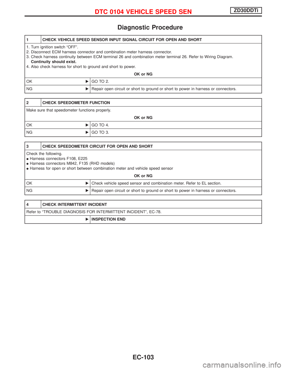
Diagnostic Procedure
1 CHECK VEHICLE SPEED SENSOR INPUT SIGNAL CIRCUIT FOR OPEN AND SHORT
1. Turn ignition switch ªOFFº.
2. Disconnect ECM harness connector and combination meter harness connector.
3. Check harness continuity between ECM terminal 26 and combination meter terminal 26. Refer to Wiring Diagram.
Continuity should exist.
4. Also check harness for short to ground and short to power.
OK or NG
OKEGO TO 2.
NGERepair open circuit or short to ground or short to power in harness or connectors.
2 CHECK SPEEDOMETER FUNCTION
Make sure that speedometer functions properly.
OK or NG
OKEGO TO 4.
NGEGO TO 3.
3 CHECK SPEEDOMETER CIRCUIT FOR OPEN AND SHORT
Check the following.
IHarness connectors F108, E225
IHarness connectors M842, F135 (RHD models)
IHarness for open or short between combination meter and vehicle speed sensor
OK or NG
OKECheck vehicle speed sensor and combination meter. Refer to EL section.
NGERepair open circuit or short to ground or short to power in harness or connectors.
4 CHECK INTERMITTENT INCIDENT
Refer to ªTROUBLE DIAGNOSIS FOR INTERMITTENT INCIDENTº, EC-78.
EINSPECTION END
DTC 0104 VEHICLE SPEED SENZD30DDTi
EC-103
Page 469 of 1767
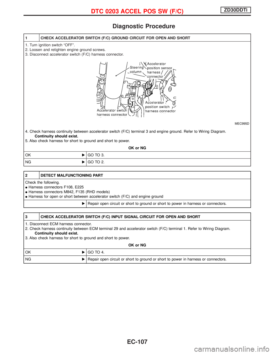
Diagnostic Procedure
1 CHECK ACCELERATOR SWITCH (F/C) GROUND CIRCUIT FOR OPEN AND SHORT
1. Turn ignition switch ªOFFº.
2. Loosen and retighten engine ground screws.
3. Disconnect accelerator switch (F/C) harness connector.
MEC995D
4. Check harness continuity between accelerator switch (F/C) terminal 3 and engine ground. Refer to Wiring Diagram.
Continuity should exist.
5. Also check harness for short to ground and short to power.
OK or NG
OKEGO TO 3.
NGEGO TO 2.
2 DETECT MALFUNCTIONING PART
Check the following.
IHarness connectors F108, E225
IHarness connectors M842, F135 (RHD models)
IHarness for open or short between accelerator switch (F/C) and engine ground
ERepair open circuit or short to ground or short to power in harness or connectors.
3 CHECK ACCELERATOR SWITCH (F/C) INPUT SIGNAL CIRCUIT FOR OPEN AND SHORT
1. Disconnect ECM harness connector.
2. Check harness continuity between ECM terminal 29 and accelerator switch (F/C) terminal 1. Refer to Wiring Diagram.
Continuity should exist.
3. Also check harness for short to ground and short to power.
OK or NG
OKEGO TO 4.
NGERepair open circuit or short to ground or short to power in harness or connectors.
DTC 0203 ACCEL POS SW (F/C)ZD30DDTi
EC-107
Page 478 of 1767
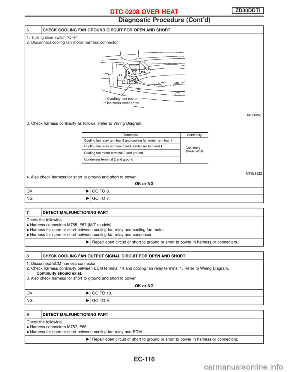
6 CHECK COOLING FAN GROUND CIRCUIT FOR OPEN AND SHORT
1. Turn ignition switch ªOFFº.
2. Disconnect cooling fan motor harness connector.
MEC024E
3. Check harness continuity as follows. Refer to Wiring Diagram.
MTBL13224. Also check harness for short to ground and short to power.
OK or NG
OKEGO TO 8.
NGEGO TO 7.
7 DETECT MALFUNCTIONING PART
Check the following.
IHarness connectors M785, F67 (M/T models)
IHarness for open or short between cooling fan relay and cooling fan motor
IHarness for open or short between cooling fan relay and condenser
ERepair open circuit or short to ground or short to power in harness or connectors.
8 CHECK COOLING FAN OUTPUT SIGNAL CIRCUIT FOR OPEN AND SHORT
1. Disconnect ECM harness connector.
2. Check harness continuity between ECM terminal 14 and cooling fan relay terminal 1. Refer to Wiring Diagram.
Continuity should exist.
3. Also check harness for short to ground and short to power.
OK or NG
OKEGO TO 10.
NGEGO TO 9.
9 DETECT MALFUNCTIONING PART
Check the following.
IHarness connectors M787, F66
IHarness for open or short between cooling fan relay and ECM
ERepair open circuit or short to ground or short to power in harness or connectors.
DTC 0208 OVER HEATZD30DDTi
Diagnostic Procedure (Cont'd)
EC-116
Page 483 of 1767
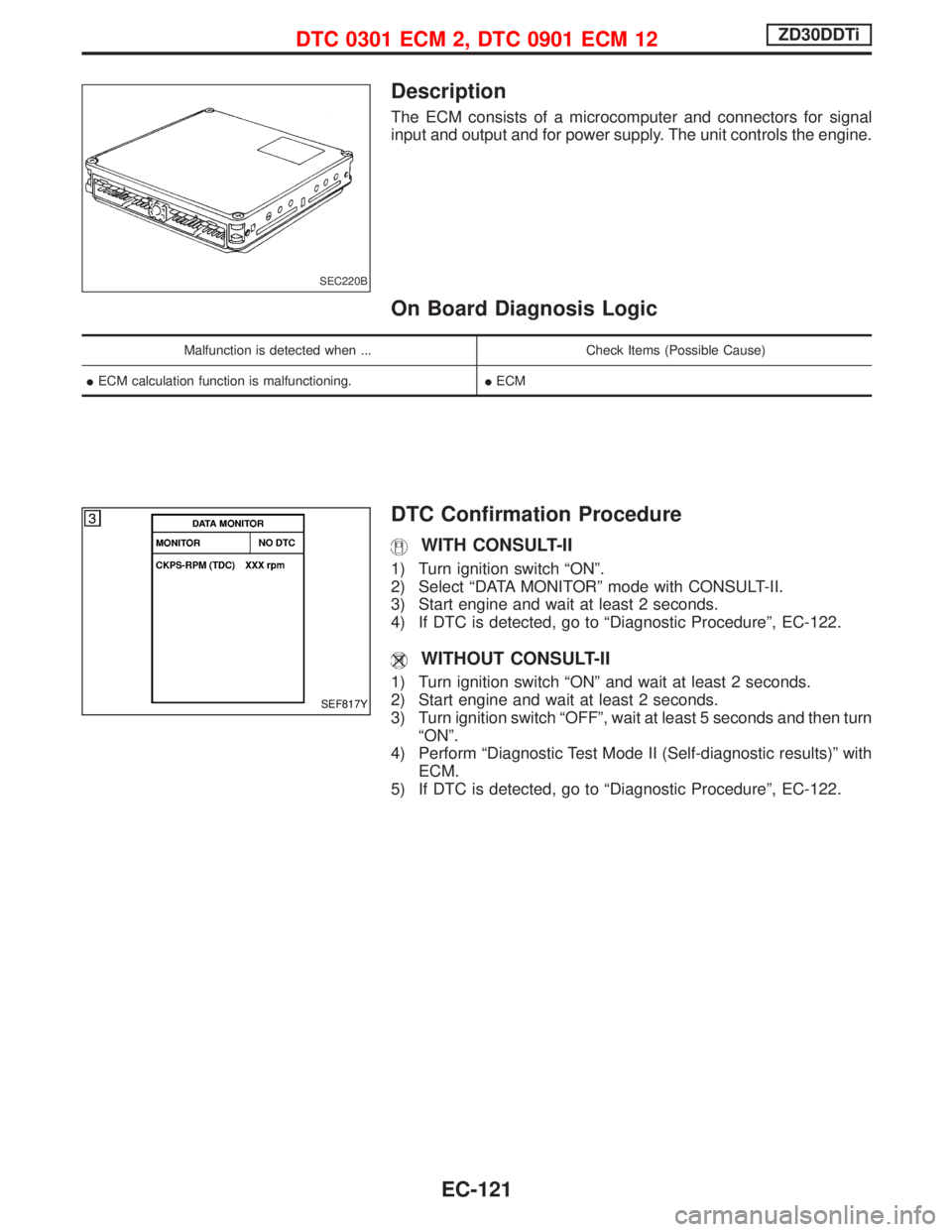
Description
The ECM consists of a microcomputer and connectors for signal
input and output and for power supply. The unit controls the engine.
On Board Diagnosis Logic
Malfunction is detected when ... Check Items (Possible Cause)
IECM calculation function is malfunctioning.IECM
DTC Confirmation Procedure
WITH CONSULT-II
1) Turn ignition switch ªONº.
2) Select ªDATA MONITORº mode with CONSULT-II.
3) Start engine and wait at least 2 seconds.
4) If DTC is detected, go to ªDiagnostic Procedureº, EC-122.
WITHOUT CONSULT-II
1) Turn ignition switch ªONº and wait at least 2 seconds.
2) Start engine and wait at least 2 seconds.
3) Turn ignition switch ªOFFº, wait at least 5 seconds and then turn
ªONº.
4) Perform ªDiagnostic Test Mode II (Self-diagnostic results)º with
ECM.
5) If DTC is detected, go to ªDiagnostic Procedureº, EC-122.
SEC220B
SEF817Y
DTC 0301 ECM 2, DTC 0901 ECM 12ZD30DDTi
EC-121