Page 584 of 1767
Description
SYSTEM DESCRIPTION
Sensor Input Signal to ECM ECM Function Actuator
Electronic controlled fuel injection pump Fuel injection signal
EGR volume
controlEGR volume control valve Crankshaft position sensor (TDC) Engine speed
Vehicle speed sensor Vehicle speed
Engine coolant temperature sensor Engine coolant temperature
Ignition switch Start signal
Throttle position sensor Throttle position
Battery Battery voltage
Mass air flow sensor Amount of intake air
Air conditioner switch Air conditioner operation
Electrical load Electrical load signal
PNP switch Park/Neutral position signal
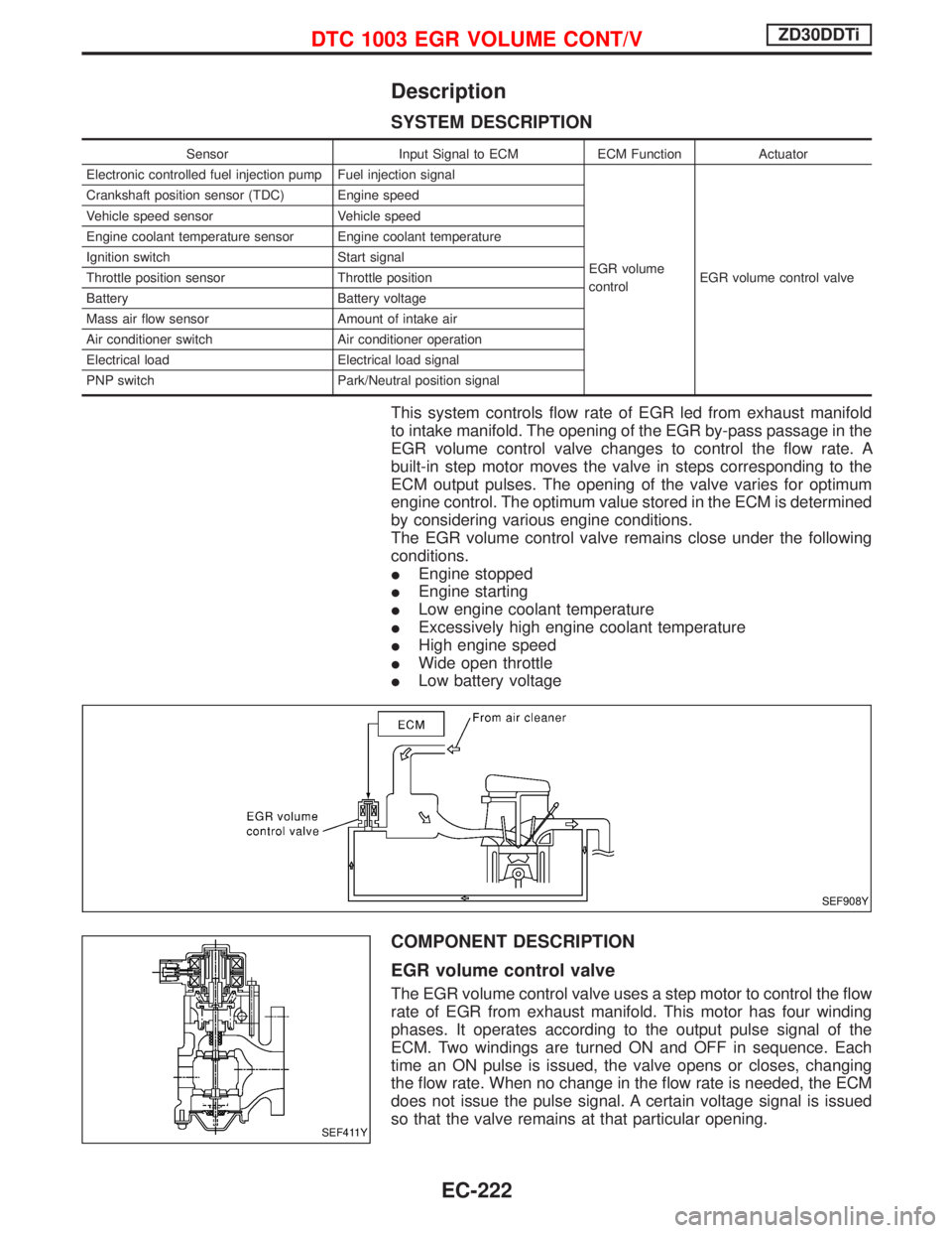
This system controls flow rate of EGR led from exhaust manifold
to intake manifold. The opening of the EGR by-pass passage in the
EGR volume control valve changes to control the flow rate. A
built-in step motor moves the valve in steps corresponding to the
ECM output pulses. The opening of the valve varies for optimum
engine control. The optimum value stored in the ECM is determined
by considering various engine conditions.
The EGR volume control valve remains close under the following
conditions.
IEngine stopped
IEngine starting
ILow engine coolant temperature
IExcessively high engine coolant temperature
IHigh engine speed
IWide open throttle
ILow battery voltage
COMPONENT DESCRIPTION
EGR volume control valve
The EGR volume control valve uses a step motor to control the flow
rate of EGR from exhaust manifold. This motor has four winding
phases. It operates according to the output pulse signal of the
ECM. Two windings are turned ON and OFF in sequence. Each
time an ON pulse is issued, the valve opens or closes, changing
the flow rate. When no change in the flow rate is needed, the ECM
does not issue the pulse signal. A certain voltage signal is issued
so that the valve remains at that particular opening.
SEF908Y
SEF411Y
DTC 1003 EGR VOLUME CONT/VZD30DDTi
EC-222
Page 591 of 1767
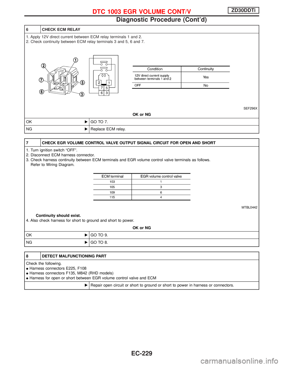
6 CHECK ECM RELAY
1. Apply 12V direct current between ECM relay terminals 1 and 2.
2. Check continuity between ECM relay terminals 3 and 5, 6 and 7.
SEF296X
OK or NG
OKEGO TO 7.
NGEReplace ECM relay.
7 CHECK EGR VOLUME CONTROL VALVE OUTPUT SIGNAL CIRCUIT FOR OPEN AND SHORT
1. Turn ignition switch ªOFFº.
2. Disconnect ECM harness connector.
3. Check harness continuity between ECM terminals and EGR volume control valve terminals as follows.
Refer to Wiring Diagram.
MTBL0442
Continuity should exist.
4. Also check harness for short to ground and short to power.
OK or NG
OKEGO TO 9.
NGEGO TO 8.
8 DETECT MALFUNCTIONING PART
Check the following.
IHarness connectors E225, F108
IHarness connectors F135, M842 (RHD models)
IHarness for open or short between EGR volume control valve and ECM
ERepair open circuit or short to ground or short to power in harness or connectors.
DTC 1003 EGR VOLUME CONT/VZD30DDTi
Diagnostic Procedure (Cont'd)
EC-229
Page 601 of 1767
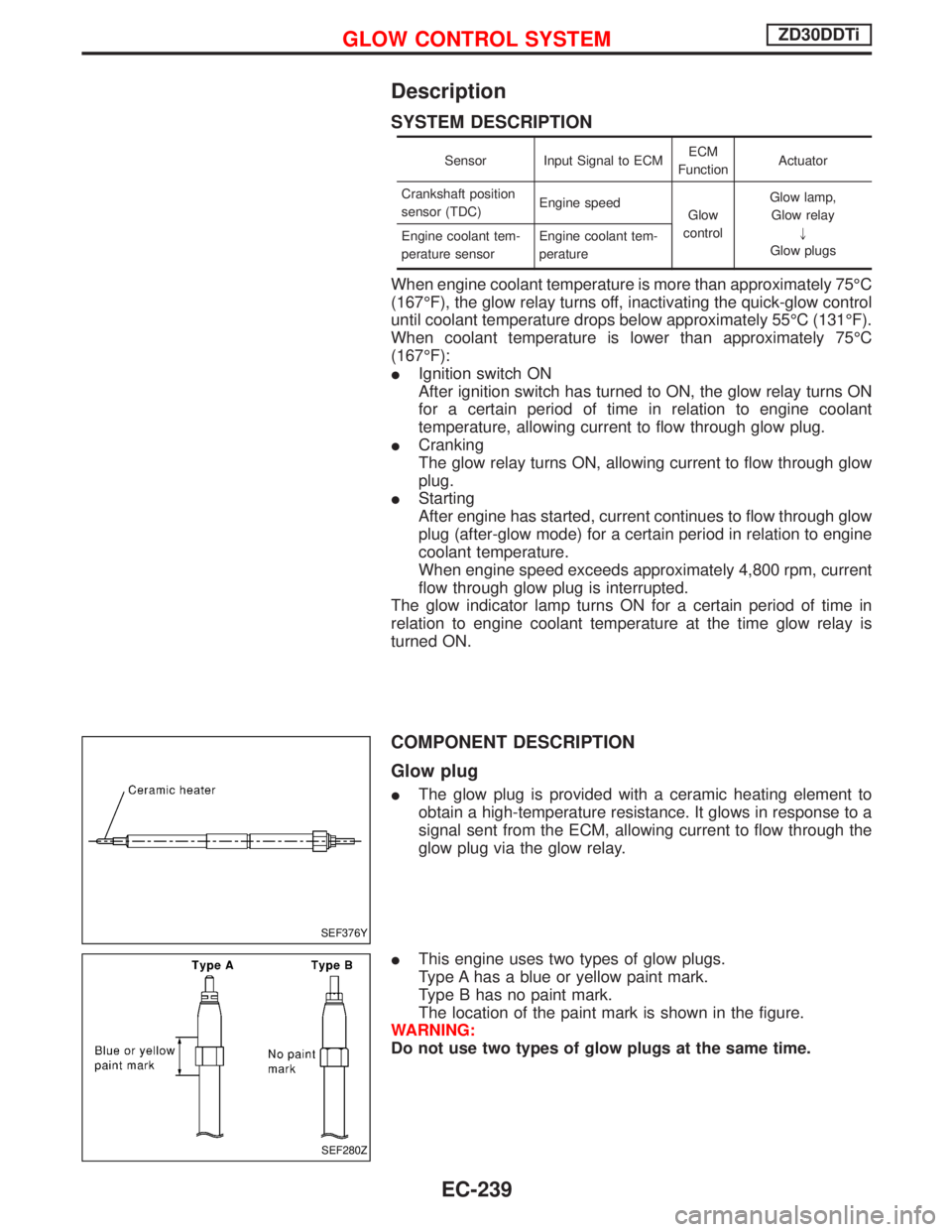
Description
SYSTEM DESCRIPTION
Sensor Input Signal to ECMECM
FunctionActuator
Crankshaft position
sensor (TDC)Engine speed
Glow
controlGlow lamp,
Glow relay
"
Glow plugs Engine coolant tem-
perature sensorEngine coolant tem-
perature
When engine coolant temperature is more than approximately 75ÉC
(167ÉF), the glow relay turns off, inactivating the quick-glow control
until coolant temperature drops below approximately 55ÉC (131ÉF).
When coolant temperature is lower than approximately 75ÉC
(167ÉF):
IIgnition switch ON
After ignition switch has turned to ON, the glow relay turns ON
for a certain period of time in relation to engine coolant
temperature, allowing current to flow through glow plug.
ICranking
The glow relay turns ON, allowing current to flow through glow
plug.
IStarting
After engine has started, current continues to flow through glow
plug (after-glow mode) for a certain period in relation to engine
coolant temperature.
When engine speed exceeds approximately 4,800 rpm, current
flow through glow plug is interrupted.
The glow indicator lamp turns ON for a certain period of time in
relation to engine coolant temperature at the time glow relay is
turned ON.
COMPONENT DESCRIPTION
Glow plug
IThe glow plug is provided with a ceramic heating element to
obtain a high-temperature resistance. It glows in response to a
signal sent from the ECM, allowing current to flow through the
glow plug via the glow relay.
IThis engine uses two types of glow plugs.
Type A has a blue or yellow paint mark.
Type B has no paint mark.
The location of the paint mark is shown in the figure.
WARNING:
Do not use two types of glow plugs at the same time.
SEF376Y
SEF280Z
GLOW CONTROL SYSTEMZD30DDTi
EC-239
Page 606 of 1767
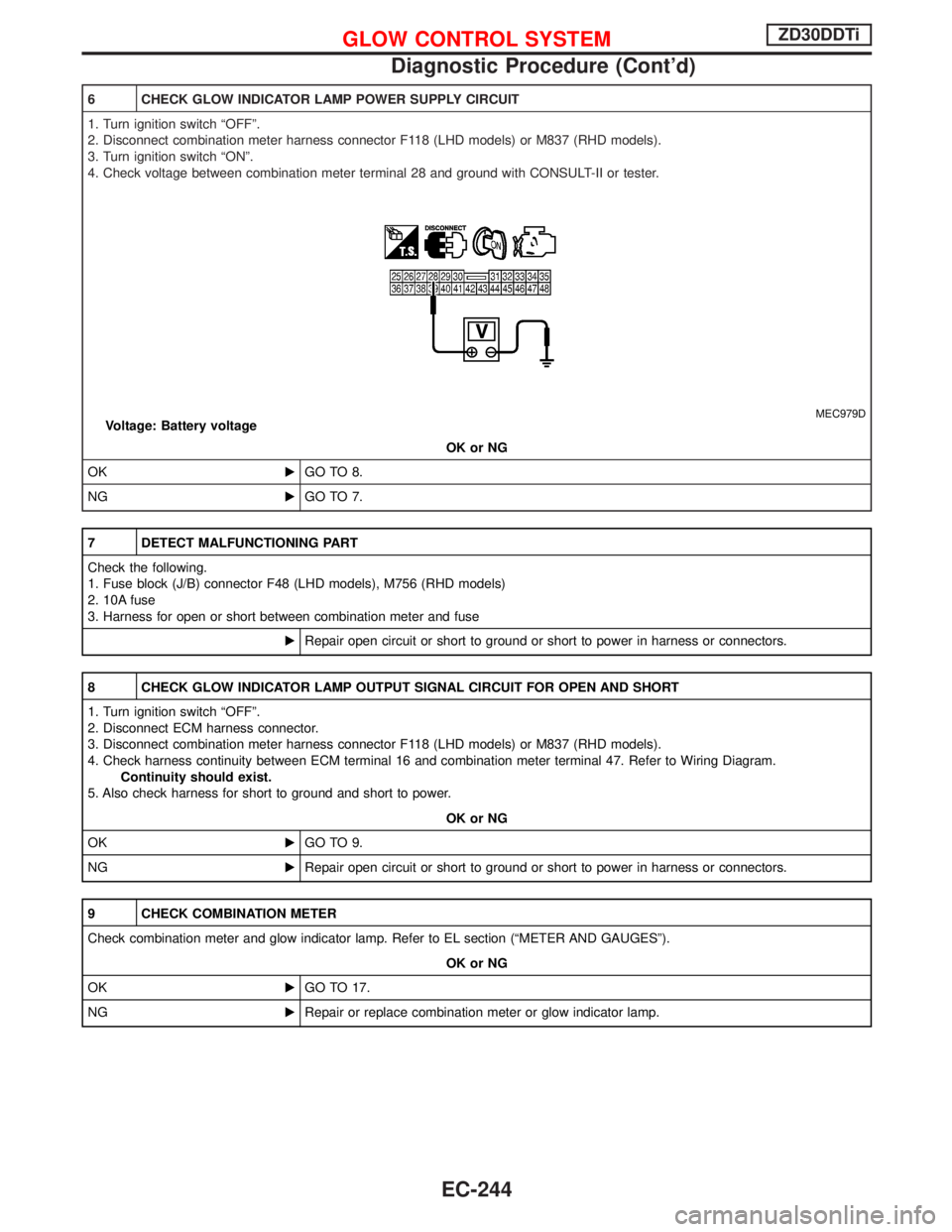
6 CHECK GLOW INDICATOR LAMP POWER SUPPLY CIRCUIT
1. Turn ignition switch ªOFFº.
2. Disconnect combination meter harness connector F118 (LHD models) or M837 (RHD models).
3. Turn ignition switch ªONº.
4. Check voltage between combination meter terminal 28 and ground with CONSULT-II or tester.
MEC979DVoltage: Battery voltage
OK or NG
OKEGO TO 8.
NGEGO TO 7.
7 DETECT MALFUNCTIONING PART
Check the following.
1. Fuse block (J/B) connector F48 (LHD models), M756 (RHD models)
2. 10A fuse
3. Harness for open or short between combination meter and fuse
ERepair open circuit or short to ground or short to power in harness or connectors.
8 CHECK GLOW INDICATOR LAMP OUTPUT SIGNAL CIRCUIT FOR OPEN AND SHORT
1. Turn ignition switch ªOFFº.
2. Disconnect ECM harness connector.
3. Disconnect combination meter harness connector F118 (LHD models) or M837 (RHD models).
4. Check harness continuity between ECM terminal 16 and combination meter terminal 47. Refer to Wiring Diagram.
Continuity should exist.
5. Also check harness for short to ground and short to power.
OK or NG
OKEGO TO 9.
NGERepair open circuit or short to ground or short to power in harness or connectors.
9 CHECK COMBINATION METER
Check combination meter and glow indicator lamp. Refer to EL section (ªMETER AND GAUGESº).
OK or NG
OKEGO TO 17.
NGERepair or replace combination meter or glow indicator lamp.
GLOW CONTROL SYSTEMZD30DDTi
Diagnostic Procedure (Cont'd)
EC-244
Page 607 of 1767
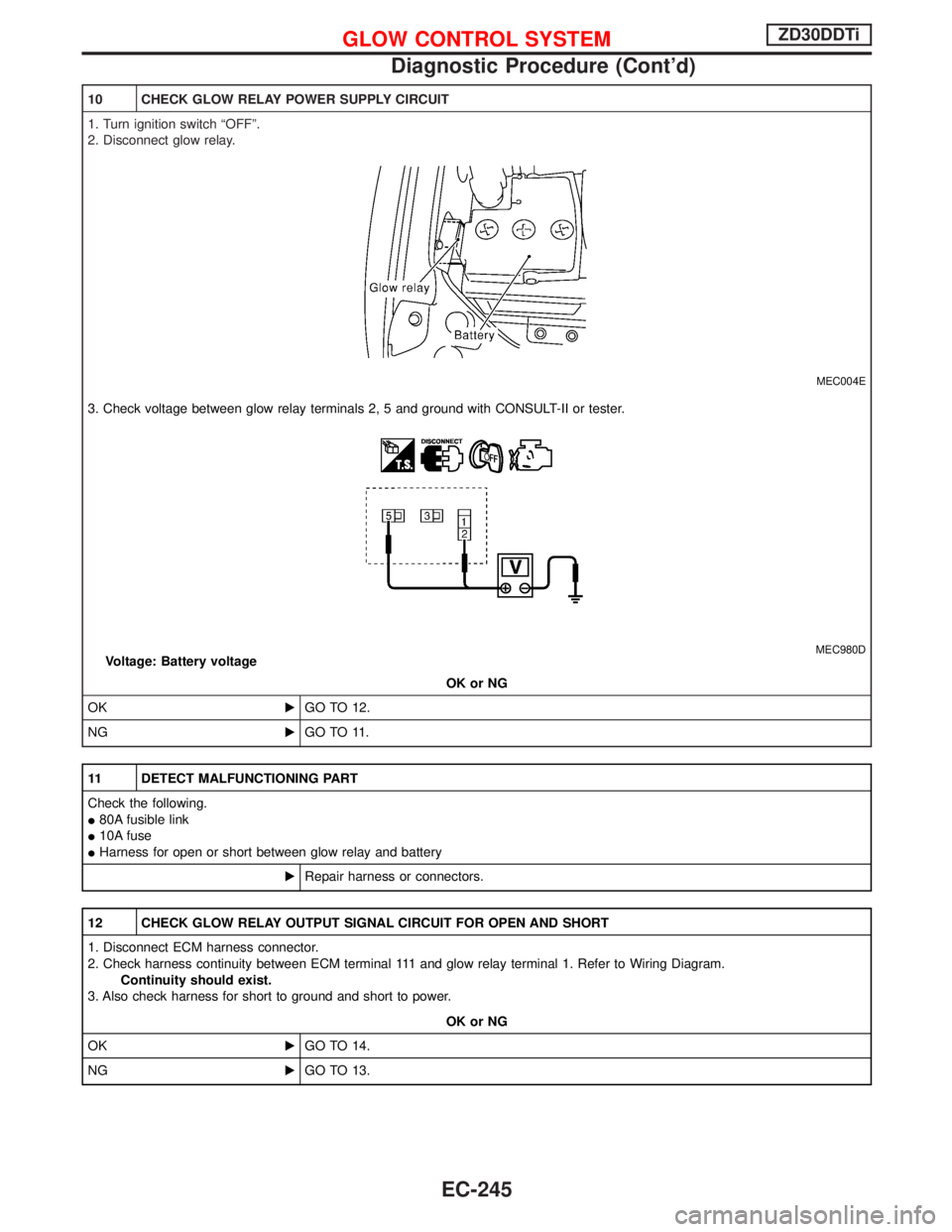
10 CHECK GLOW RELAY POWER SUPPLY CIRCUIT
1. Turn ignition switch ªOFFº.
2. Disconnect glow relay.
MEC004E
3. Check voltage between glow relay terminals 2, 5 and ground with CONSULT-II or tester.
MEC980DVoltage: Battery voltage
OK or NG
OKEGO TO 12.
NGEGO TO 11.
11 DETECT MALFUNCTIONING PART
Check the following.
I80A fusible link
I10A fuse
IHarness for open or short between glow relay and battery
ERepair harness or connectors.
12 CHECK GLOW RELAY OUTPUT SIGNAL CIRCUIT FOR OPEN AND SHORT
1. Disconnect ECM harness connector.
2. Check harness continuity between ECM terminal 111 and glow relay terminal 1. Refer to Wiring Diagram.
Continuity should exist.
3. Also check harness for short to ground and short to power.
OK or NG
OKEGO TO 14.
NGEGO TO 13.
GLOW CONTROL SYSTEMZD30DDTi
Diagnostic Procedure (Cont'd)
EC-245
Page 611 of 1767
Diagnostic Procedure
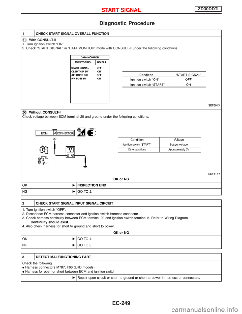
1 CHECK START SIGNAL OVERALL FUNCTION
With CONSULT-II
1. Turn ignition switch ªONº.
2. Check ªSTART SIGNALº in ªDATA MONITORº mode with CONSULT-II under the following conditions.
SEF604X
Without CONSULT-II
Check voltage between ECM terminal 20 and ground under the following conditions.
SEF415Y
OK or NG
OKEINSPECTION END
NGEGO TO 2.
2 CHECK START SIGNAL INPUT SIGNAL CIRCUIT
1. Turn ignition switch ªOFFº.
2. Disconnect ECM harness connector and ignition switch harness connector.
3. Check harness continuity between ECM terminal 20 and ignition switch terminal 5. Refer to Wiring Diagram.
Continuity should exist.
4. Also check harness for short to ground and short to power.
OK or NG
OKEGO TO 4.
NGEGO TO 3.
3 DETECT MALFUNCTIONING PART
Check the following.
IHarness connectors M787, F66 (LHD models)
IHarness for open or short between ECM and ignition switch
ERepair open circuit or short to ground or short to power in harness or connectors.
START SIGNALZD30DDTi
EC-249
Page 615 of 1767
Diagnostic Procedure
FOR M/T MODELS
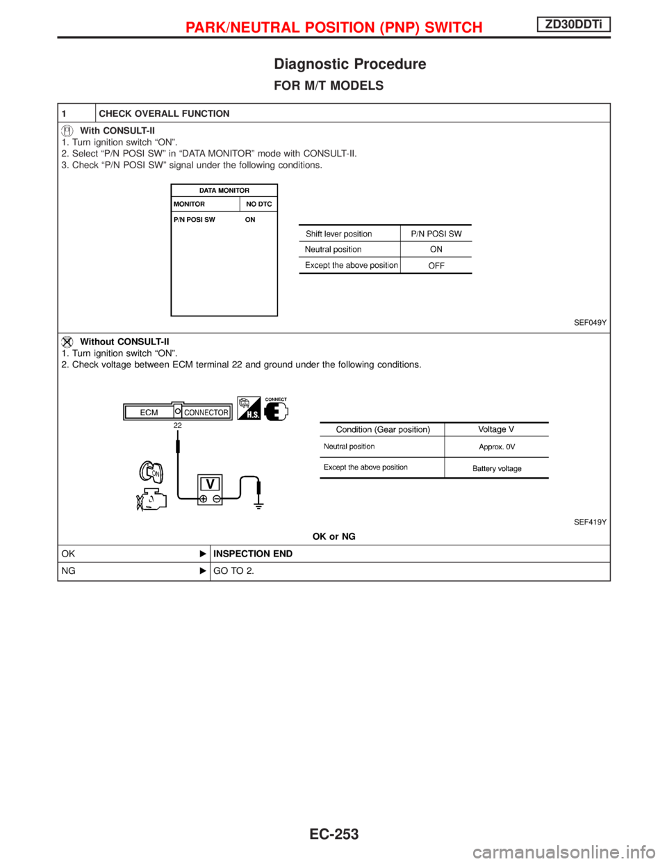
1 CHECK OVERALL FUNCTION
With CONSULT-II
1. Turn ignition switch ªONº.
2. Select ªP/N POSI SWº in ªDATA MONITORº mode with CONSULT-II.
3. Check ªP/N POSI SWº signal under the following conditions.
SEF049Y
Without CONSULT-II
1. Turn ignition switch ªONº.
2. Check voltage between ECM terminal 22 and ground under the following conditions.
SEF419Y
OK or NG
OKEINSPECTION END
NGEGO TO 2.
PARK/NEUTRAL POSITION (PNP) SWITCHZD30DDTi
EC-253
Page 616 of 1767
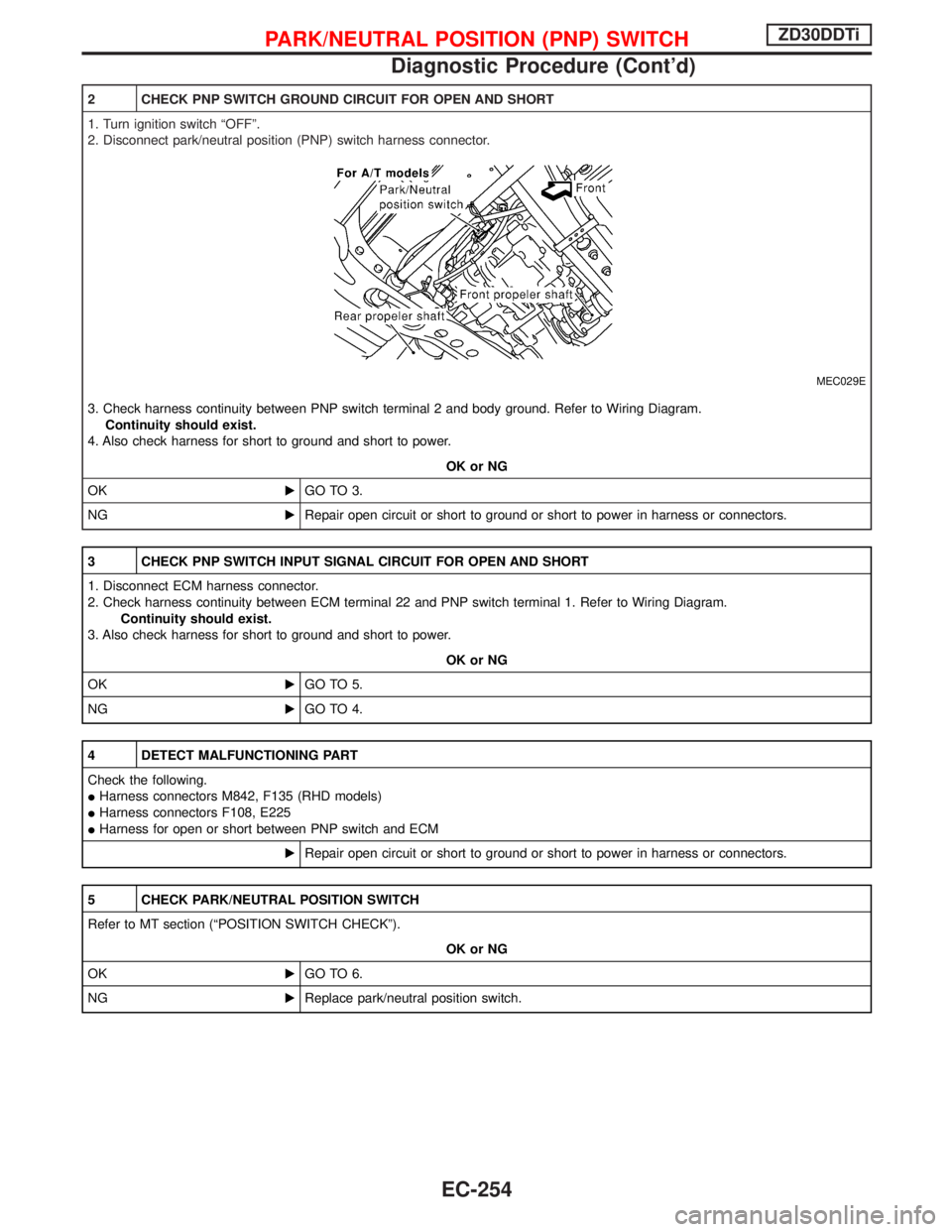
2 CHECK PNP SWITCH GROUND CIRCUIT FOR OPEN AND SHORT
1. Turn ignition switch ªOFFº.
2. Disconnect park/neutral position (PNP) switch harness connector.
MEC029E
3. Check harness continuity between PNP switch terminal 2 and body ground. Refer to Wiring Diagram.
Continuity should exist.
4. Also check harness for short to ground and short to power.
OK or NG
OKEGO TO 3.
NGERepair open circuit or short to ground or short to power in harness or connectors.
3 CHECK PNP SWITCH INPUT SIGNAL CIRCUIT FOR OPEN AND SHORT
1. Disconnect ECM harness connector.
2. Check harness continuity between ECM terminal 22 and PNP switch terminal 1. Refer to Wiring Diagram.
Continuity should exist.
3. Also check harness for short to ground and short to power.
OK or NG
OKEGO TO 5.
NGEGO TO 4.
4 DETECT MALFUNCTIONING PART
Check the following.
IHarness connectors M842, F135 (RHD models)
IHarness connectors F108, E225
IHarness for open or short between PNP switch and ECM
ERepair open circuit or short to ground or short to power in harness or connectors.
5 CHECK PARK/NEUTRAL POSITION SWITCH
Refer to MT section (ªPOSITION SWITCH CHECKº).
OK or NG
OKEGO TO 6.
NGEReplace park/neutral position switch.
PARK/NEUTRAL POSITION (PNP) SWITCHZD30DDTi
Diagnostic Procedure (Cont'd)
EC-254