Page 25 of 246

CONNECT Nav
24
Once the modem has been proper-
ly installed, the portable computer can
use all the applications provided for
telematic connections to data base -
external servers, etc.; more particu-
larly the following can be used:
– Hiper Terminal;
– Microsoft Explorer or Netscape
for Internet and its applications (pro-
vided the user has an “Internet
provider”);
– Microsoft Mail or Groupwise (for
e-mail address).To activate the Modem function,
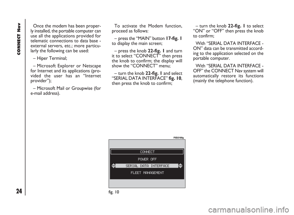
proceed as follows:
– press the “MAIN” button 17-fig. 1
to display the main screen;
– press the knob 22-fig. 1and turn
it to select “CONNECT” then press
the knob to confirm; the display will
show the “CONNECT” menu;
– turn the knob 22-fig. 1and select
“SERIAL DATA INTERFACE” fig. 10,
then press the knob to confirm;– turn the knob 22-fig. 1to select
“ON” or “OFF” then press the knob
to confirm;
With “SERIAL DATA INTERFACE -
ON” data can be transmitted accord-
ing to the application selected on the
portable computer.
With “SERIAL DATA INTERFACE -
OFF” the CONNECT Nav system will
automatically restore its functions
(mainly the telephone function).
fig. 10
F0D2180g
Page 26 of 246

CONNECT Nav
25
FLEET MANAGEMENT
When choosing this function, the
CONNECT Nav system sends auto-
matically SMS messages (to a suitable
preset receiver, e.g. a control centre)
containing the position of the vehicle
mounting the CONNECT Nav.
SMS messages are structured as fol-
lows:
– vehicle location (latitude and lon-
gitude)
– city (only with navigation CD in-
serted; if no CD is inserted, the field
is empty)
– street (only with navigation CD in-
serted; if no CD is inserted, the field
is empty)
– time and date
– vehicle ID (number plate).Example: LT:-2.30000;LG:-2.40000; #Benevento;#
Via Basilio Giannelli;#S:30;M:20; H:19;ND:2;D:02;MH:10;Y:2001;#BR757AM;#
To activate the FLEET MANAGE-
MENT function, proceed as follows:
– press the “MAIN” button 17-fig. 1
to display the main screen;
– turn and press the knob 22-fig. 1
to select and confirm “CONNECT”;
the display will show the “CON-
NECT” menu;
– turn and press the knob 22-fig. 1
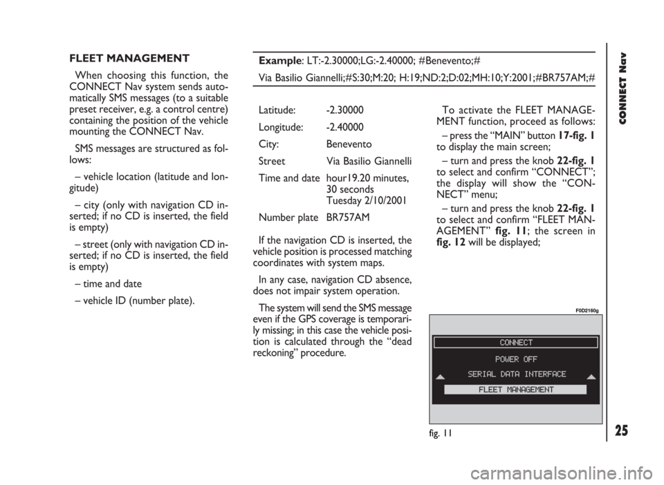
to select and confirm “FLEET MAN-
AGEMENT” fig. 11; the screen in
fig. 12will be displayed; Latitude: -2.30000
Longitude: -2.40000
City: Benevento
Street Via Basilio Giannelli
Time and date hour19.20 minutes,
30 seconds
Tuesday 2/10/2001
Number plate BR757AM
If the navigation CD is inserted, the
vehicle position is processed matching
coordinates with system maps.
In any case, navigation CD absence,
does not impair system operation.
The system will send the SMS message
even if the GPS coverage is temporari-
ly missing; in this case the vehicle posi-
tion is calculated through the “dead
reckoning” procedure.
fig. 11
F0D2160g
Page 27 of 246
CONNECT Nav
26
– select and confirm “Sending mode”
by rotating and pressing the knob 22-
fig. 1, the screen in fig. 13will be dis-
played;– select and confirm “ON” (or
“OFF” if you want to deactivate it) by
rotating and pressing the knob 22-
fig. 1;
– turn the knob 22-fig. 1to select
“EVENT MODE” then press the knob
to confirm; the condition shown in
fig. 14will be displayed;
– turn the knob 22-fig. 1to select
“ROUTE (km/mi)” or “TIME (hours)”,
then press the knob to confirm. Selecting “ROUTE (km/mi)” the
message will be sent at the number
of km or miles set in “DATA FRE-
QUENCY SEND”; selecting “TIME
(hours)” the message will be sent at
the number of hours set in “DATA
FREQUENCY SEND”;
– turn knob 22-fig. 1to select “DA-
TA FREQUENCY SEND” then press
to confirm; according to the previously
set parameter (route or time) the dis-
play will show the screen in fig. 15or
fig. 16;
fig. 12
F0D2162g
fig. 13
F0D2163g
fig. 14
F0D2164g
fig. 15
F0D2165g
Page 28 of 246

CONNECT Nav
27fig. 16
F0D2168g
fig. 17
F0D2166g
fig. 18
F0D2167g
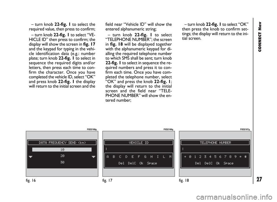
– turn knob 22-fig. 1to select the
required value, then press to confirm;
– turn knob 22-fig. 1to select “VE-
HICLE ID” then press to confirm; the
display will show the screen in fig. 17
and the keypad for typing in the vehi-
cle identification data (e.g.: number
plate; turn knob 22-fig. 1to select in
sequence the required digits and/or
letters, then press each time to con-
firm the character. Once you have
completed the vehicle ID, select “OK”
and press knob 22-fig. 1the display
will return to the initial screen and thefield near “Vehicle ID” will show the
entered alphanumeric string;
– turn knob 22-fig. 1to select
“TELEPHONE NUMBER”; the screen
in fig. 18will be displayed together
with the alphanumeric keypad for di-
alling the required telephone number
to which SMS shall be sent; turn knob
22-fig. 1to select in sequence the re-
quired numbers and press it to con-
firm each time. Once you have com-
pleted the telephone number, select
“OK” and press the knob 22-fig. 1;
the display will return to the initial
screen and the field near “TELE-
PHONE NUMBER” will show the en-
tered number;– turn knob 22-fig. 1to select “OK”
then press the knob to confirm set-
tings; the display will return to the ini-
tial screen.
Page 29 of 246
CONNECT Nav
28
Operation requirements
The “FLEET MANAGEMENT” func-
tion is operational if the following con-
ditions are present:
– “FLEET MANAGEMENT” function
active;
– service centre telephone number
entered;
– vehicle ID entered;
– frequency set (timeor route);
– CONNECT on;
– SIM card inserted;
– sufficient credit;
– GSM coverage.Failing message sending
Should one or more of the following
conditions - e.g.: CONNECT off, SIM
card not inserted or disabled, insuffi-
cient GSM coverage - take place when
sending SMS messages, their regular
transmission will be impaired.
In this case the system will store the
messages and send them later (max.
10 messages) when normal operating
conditions are restored.IMPORTANTMore particularly,
the condition of CONNECT off will
store the messages with incorrect po-
sition, since the first position present
at system switching on will be detect-
ed.
Page 30 of 246

29
CONNECT Nav
The audio system is turned on by
pressing briefly the “AUDIO” but-
ton18-fig. 1which displays the main
functions of the radio.
Keeping the “AUDIO” button 18-
fig. 1, pressed longer, with the audio
system on and any operating mode ac-
tive, the “stand-by” mode is switched
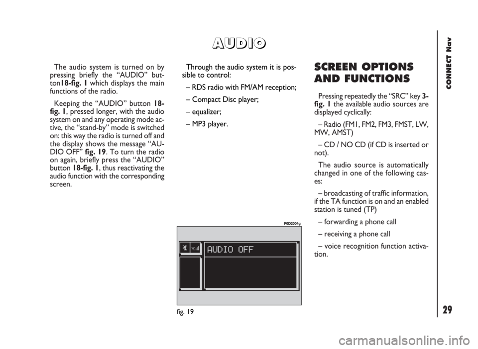
on: this way the radio is turned off and
the display shows the message “AU-
DIO OFF” fig. 19. To turn the radio
on again, briefly press the “AUDIO”
button 18-fig. 1, thus reactivating the
audio function with the corresponding
screen. SCREEN OPTIONS
AND FUNCTIONS
Pressing repeatedly the “SRC” key 3-
fig. 1the available audio sources are
displayed cyclically:
– Radio (FM1, FM2, FM3, FMST, LW,
MW, AMST)
– CD / NO CD (if CD is inserted or
not).
The audio source is automatically
changed in one of the following cas-
es:
– broadcasting of traffic information,
if the TA function is on and an enabled
station is tuned (TP)
– forwarding a phone call
– receiving a phone call
– voice recognition function activa-
tion.
A A
U U
D D
I I
O O
Through the audio system it is pos-
sible to control:
– RDS radio with FM/AM reception;
– Compact Disc player;
– equalizer;
– MP3 player.
fig. 19
F0D2004g
Page 31 of 246

CONNECT Nav
30
RADIO MODE
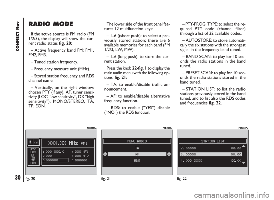
If the active source is FM radio (FM
1/2/3), the display will show the cur-
rent radio status fig. 20:
– Active frequency band FM: FM1,
FM2, FM3.
– Tuned station frequency.
– Frequency measure unit (MHz).
– Stored station frequency and RDS
channel name.
– Vertically, on the right window:
chosen PTY (if any), AF, tuner sensi-
tivity (LOC “low sensitivity”, DX “high
sensitivity”), MONO/STEREO, TA,
TP, EON.The lower side of the front panel fea-
tures 12 multifunction keys:
– 1..6 ((short push): to select a pre-
viously stored station; there are 6
available memories for each band (FM
1/2/3, LW, MW).
– 1..6 (long push): to store the cur-
rent station.
Press the knob 22-fig. 1to display the
main audio menu with the following op-
tions, fig. 21:
– TA: to enable/disable traffic an-
nouncement.
– AF: to enable/disable alternative
frequency function.
– RDS: to enable (“YES”) disable
(“NO”) the RDS function.– PTY-PROG. TYPE: to select the re-
quired PTY code (channel filter)
through a list of 32 available codes.
– AUTOSTORE: to store automati-
cally the six stations with the strongest
signal in the frequency band tuned.
– BAND SCAN: to play for 10 sec-
onds the radio stations in the band
tuned.
– PRESET SCAN: to play for 10 sec-
onds the radio stations stored in the
band tuned.
– STATION LIST: to list the radio
stations previously stored in the band
tuned, and to list also the RDS codes
and frequencies fig. 22.
fig. 20
F0D2005g
fig. 21
F0D2006g
fig. 22
F0D2007g
Page 32 of 246

31
CONNECT Nav
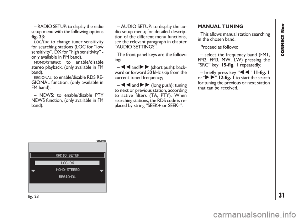
– RADIO SETUP: to display the radio
setup menu with the following options
fig. 23:
LOC/DX: to change tuner sensitivity
for searching stations (LOC for “low
sensitivity”, DX for “high sensitivity” -
only available in FM band).
MONO/STEREO: to enable/disable
stereo playback, (only available in FM
band).
REGIONAL: to enable/disable RDS RE-
GIONAL function, (only available in
FM band).
– NEWS: to enable/disable PTY
NEWS function, (only available in FM
band).– AUDIO SETUP: to display the au-
dio setup menu; for detailed descrip-
tion of the different menu functions,
see the relevant paragraph in chapter
“AUDIO SETTINGS”.
The front panel keys are the follow-
ing:
–
÷and ˜(short push): back-
ward or forward 50 kHz skip from the
current tuned frequency;
–
÷and ˜(long push): tuning
to next or previous station, according
to active filters (TA, PTY). When
searching stations, the RDS code is re-
placed by string “SEEK+ or SEEK-”.MANUAL TUNING
This allows manual station searching
in the chosen band.
Proceed as follows:
– select the frequency band (FM1,
FM2, FM3, MW, LW) pressing the
“SRC” key 15-fig. 1repeatedly;
– briefly press key “
÷” 11-fig. 1
or “
˜” 12-fig. 1to start the search
for tuning the previous or next station
that can be received.
fig. 23
F0D2008g