2002 DODGE RAM lock
[x] Cancel search: lockPage 1333 of 2255
(20) Raise and support the vehicle.
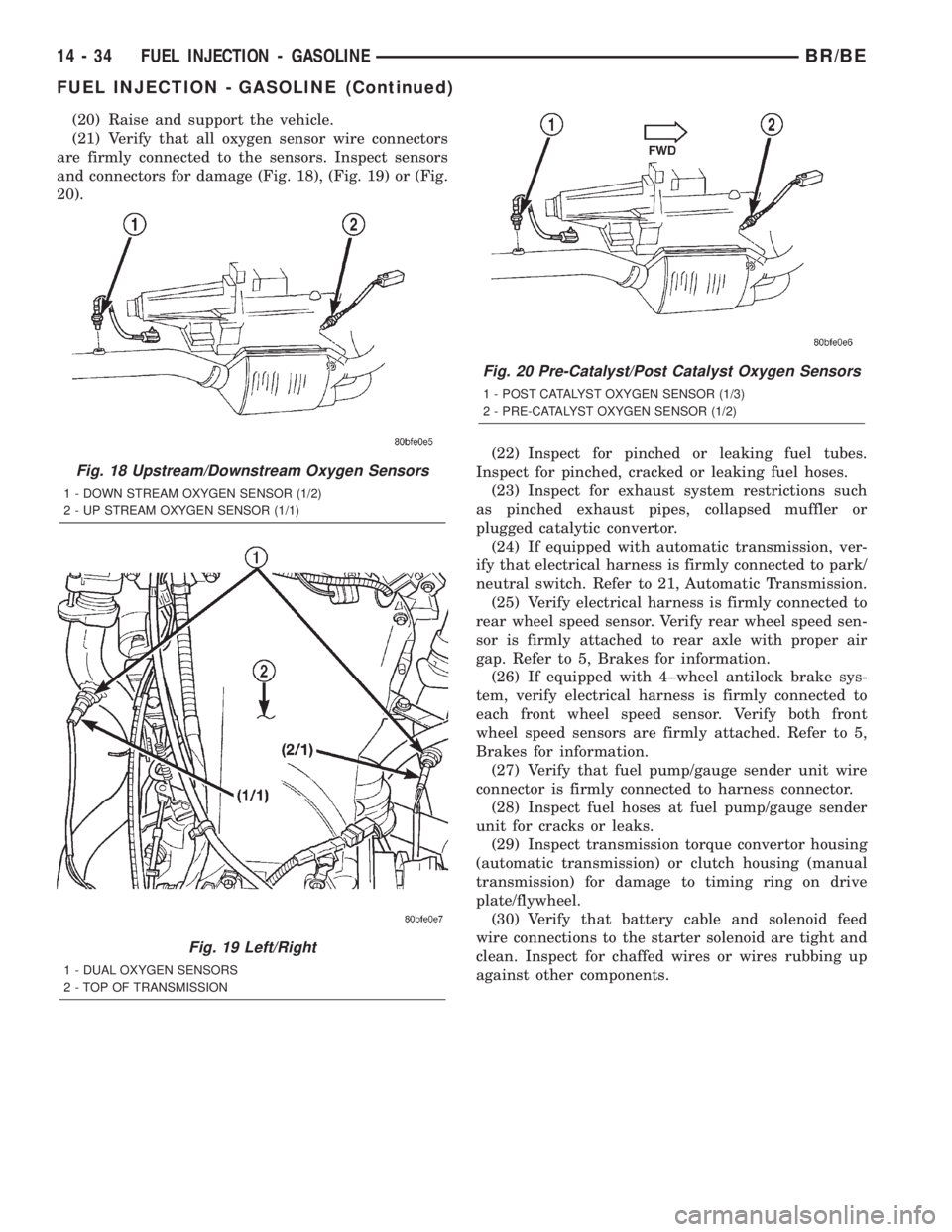
(21) Verify that all oxygen sensor wire connectors
are firmly connected to the sensors. Inspect sensors
and connectors for damage (Fig. 18), (Fig. 19) or (Fig.
20).
(22) Inspect for pinched or leaking fuel tubes.
Inspect for pinched, cracked or leaking fuel hoses.
(23) Inspect for exhaust system restrictions such
as pinched exhaust pipes, collapsed muffler or
plugged catalytic convertor.
(24) If equipped with automatic transmission, ver-
ify that electrical harness is firmly connected to park/
neutral switch. Refer to 21, Automatic Transmission.
(25) Verify electrical harness is firmly connected to
rear wheel speed sensor. Verify rear wheel speed sen-
sor is firmly attached to rear axle with proper air
gap. Refer to 5, Brakes for information.
(26) If equipped with 4±wheel antilock brake sys-
tem, verify electrical harness is firmly connected to
each front wheel speed sensor. Verify both front
wheel speed sensors are firmly attached. Refer to 5,
Brakes for information.
(27) Verify that fuel pump/gauge sender unit wire
connector is firmly connected to harness connector.
(28) Inspect fuel hoses at fuel pump/gauge sender
unit for cracks or leaks.
(29) Inspect transmission torque convertor housing
(automatic transmission) or clutch housing (manual
transmission) for damage to timing ring on drive
plate/flywheel.
(30) Verify that battery cable and solenoid feed
wire connections to the starter solenoid are tight and
clean. Inspect for chaffed wires or wires rubbing up
against other components.
Fig. 18 Upstream/Downstream Oxygen Sensors
1 - DOWN STREAM OXYGEN SENSOR (1/2)
2 - UP STREAM OXYGEN SENSOR (1/1)
Fig. 19 Left/Right
1 - DUAL OXYGEN SENSORS
2 - TOP OF TRANSMISSION
Fig. 20 Pre-Catalyst/Post Catalyst Oxygen Sensors
1 - POST CATALYST OXYGEN SENSOR (1/3)
2 - PRE-CATALYST OXYGEN SENSOR (1/2)
14 - 34 FUEL INJECTION - GASOLINEBR/BE
FUEL INJECTION - GASOLINE (Continued)
Page 1335 of 2255
ACCELERATOR PEDAL
REMOVAL
CAUTION: Be careful not to damage or kink the
cable core wire (within the cable sheathing) while
servicing accelerator pedal or cables.
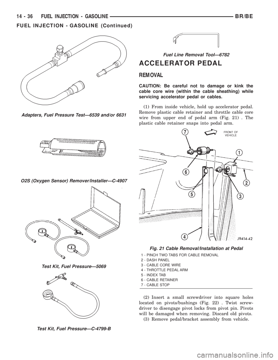
(1) From inside vehicle, hold up accelerator pedal.
Remove plastic cable retainer and throttle cable core
wire from upper end of pedal arm (Fig. 21) . The
plastic cable retainer snaps into pedal arm.
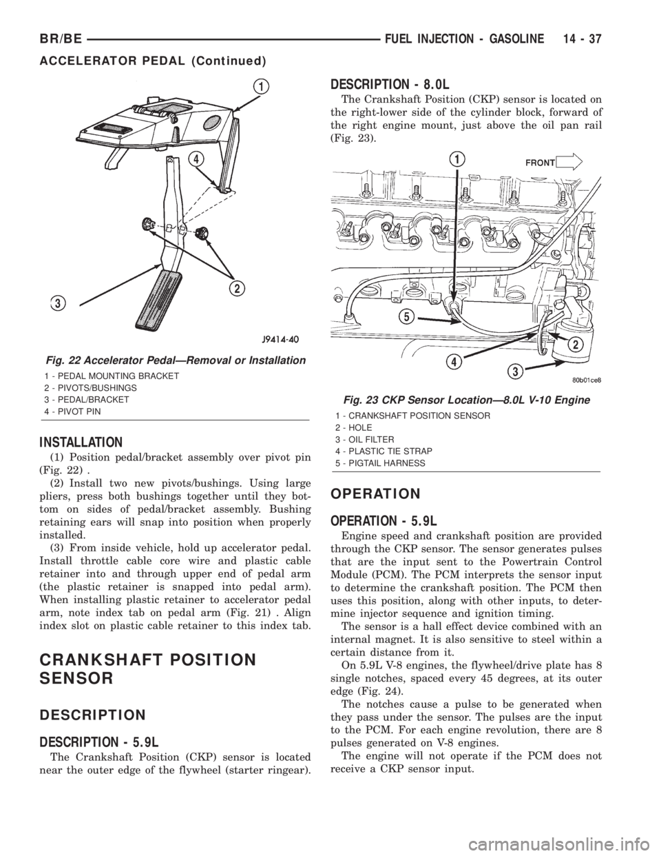
(2) Insert a small screwdriver into square holes
located on pivots/bushings (Fig. 22) . Twist screw-
driver to disengage pivot locks from pivot pin. Pivots
will be damaged when removing. Discard old pivots.
(3) Remove pedal/bracket assembly from vehicle.
Adapters, Fuel Pressure TestÐ6539 and/or 6631
O2S (Oxygen Sensor) Remover/InstallerÐC-4907
Test Kit, Fuel PressureÐ5069
Test Kit, Fuel PressureÐC-4799-B
Fuel Line Removal ToolÐ6782
Fig. 21 Cable Removal/Installation at Pedal
1 - PINCH TWO TABS FOR CABLE REMOVAL
2 - DASH PANEL
3 - CABLE CORE WIRE
4 - THROTTLE PEDAL ARM
5 - INDEX TAB
6 - CABLE RETAINER
7 - CABLE STOP
14 - 36 FUEL INJECTION - GASOLINEBR/BE
FUEL INJECTION - GASOLINE (Continued)
Page 1336 of 2255
INSTALLATION
(1) Position pedal/bracket assembly over pivot pin
(Fig. 22) .
(2) Install two new pivots/bushings. Using large
pliers, press both bushings together until they bot-
tom on sides of pedal/bracket assembly. Bushing
retaining ears will snap into position when properly
installed.
(3) From inside vehicle, hold up accelerator pedal.
Install throttle cable core wire and plastic cable
retainer into and through upper end of pedal arm
(the plastic retainer is snapped into pedal arm).
When installing plastic retainer to accelerator pedal
arm, note index tab on pedal arm (Fig. 21) . Align
index slot on plastic cable retainer to this index tab.
CRANKSHAFT POSITION
SENSOR
DESCRIPTION
DESCRIPTION - 5.9L
The Crankshaft Position (CKP) sensor is located
near the outer edge of the flywheel (starter ringear).
DESCRIPTION - 8.0L
The Crankshaft Position (CKP) sensor is located on
the right-lower side of the cylinder block, forward of
the right engine mount, just above the oil pan rail
(Fig. 23).
OPERATION
OPERATION - 5.9L
Engine speed and crankshaft position are provided
through the CKP sensor. The sensor generates pulses
that are the input sent to the Powertrain Control
Module (PCM). The PCM interprets the sensor input
to determine the crankshaft position. The PCM then
uses this position, along with other inputs, to deter-
mine injector sequence and ignition timing.
The sensor is a hall effect device combined with an
internal magnet. It is also sensitive to steel within a
certain distance from it.
On 5.9L V-8 engines, the flywheel/drive plate has 8
single notches, spaced every 45 degrees, at its outer
edge (Fig. 24).
The notches cause a pulse to be generated when
they pass under the sensor. The pulses are the input
to the PCM. For each engine revolution, there are 8
pulses generated on V-8 engines.
The engine will not operate if the PCM does not
receive a CKP sensor input.
Fig. 22 Accelerator PedalÐRemoval or Installation
1 - PEDAL MOUNTING BRACKET
2 - PIVOTS/BUSHINGS
3 - PEDAL/BRACKET
4 - PIVOT PIN
Fig. 23 CKP Sensor LocationÐ8.0L V-10 Engine
1 - CRANKSHAFT POSITION SENSOR
2 - HOLE
3 - OIL FILTER
4 - PLASTIC TIE STRAP
5 - PIGTAIL HARNESS
BR/BEFUEL INJECTION - GASOLINE 14 - 37
ACCELERATOR PEDAL (Continued)
Page 1337 of 2255
OPERATION - 8.0L
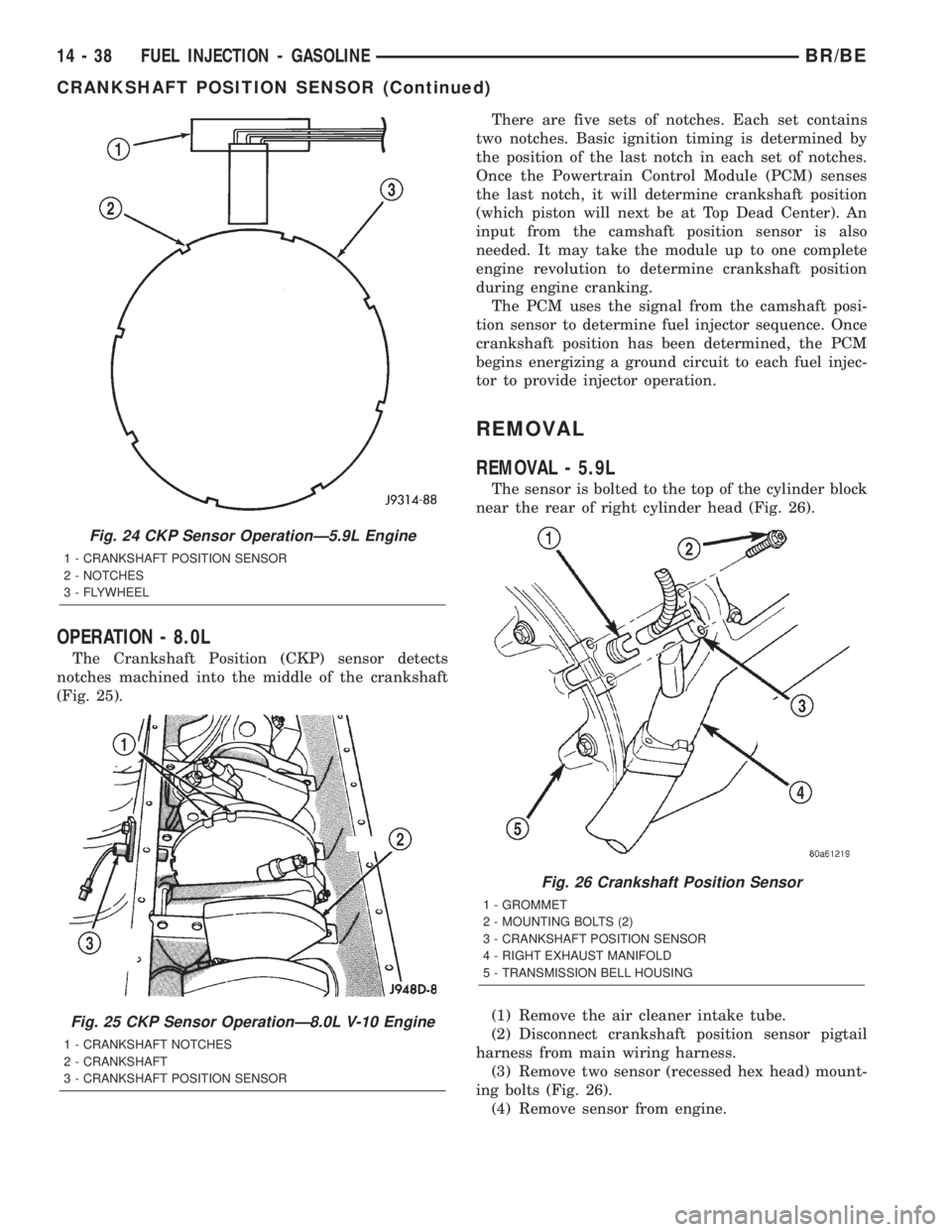
The Crankshaft Position (CKP) sensor detects
notches machined into the middle of the crankshaft
(Fig. 25).There are five sets of notches. Each set contains
two notches. Basic ignition timing is determined by
the position of the last notch in each set of notches.
Once the Powertrain Control Module (PCM) senses
the last notch, it will determine crankshaft position
(which piston will next be at Top Dead Center). An
input from the camshaft position sensor is also
needed. It may take the module up to one complete
engine revolution to determine crankshaft position
during engine cranking.
The PCM uses the signal from the camshaft posi-
tion sensor to determine fuel injector sequence. Once
crankshaft position has been determined, the PCM
begins energizing a ground circuit to each fuel injec-
tor to provide injector operation.
REMOVAL
REMOVAL - 5.9L
The sensor is bolted to the top of the cylinder block
near the rear of right cylinder head (Fig. 26).
(1) Remove the air cleaner intake tube.
(2) Disconnect crankshaft position sensor pigtail
harness from main wiring harness.
(3) Remove two sensor (recessed hex head) mount-
ing bolts (Fig. 26).
(4) Remove sensor from engine.
Fig. 24 CKP Sensor OperationÐ5.9L Engine
1 - CRANKSHAFT POSITION SENSOR
2 - NOTCHES
3 - FLYWHEEL
Fig. 25 CKP Sensor OperationÐ8.0L V-10 Engine
1 - CRANKSHAFT NOTCHES
2 - CRANKSHAFT
3 - CRANKSHAFT POSITION SENSOR
Fig. 26 Crankshaft Position Sensor
1 - GROMMET
2 - MOUNTING BOLTS (2)
3 - CRANKSHAFT POSITION SENSOR
4 - RIGHT EXHAUST MANIFOLD
5 - TRANSMISSION BELL HOUSING
14 - 38 FUEL INJECTION - GASOLINEBR/BE
CRANKSHAFT POSITION SENSOR (Continued)
Page 1338 of 2255
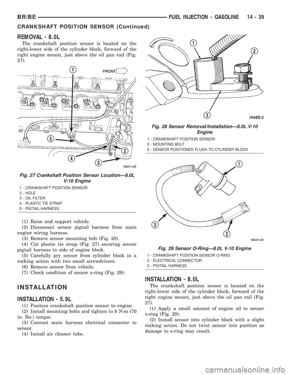
REMOVAL - 8.0L
The crankshaft position sensor is located on the
right-lower side of the cylinder block, forward of the
right engine mount, just above the oil pan rail (Fig.
27).
(1) Raise and support vehicle.
(2) Disconnect sensor pigtail harness from main
engine wiring harness.
(3) Remove sensor mounting bolt (Fig. 28).
(4) Cut plastic tie strap (Fig. 27) securing sensor
pigtail harness to side of engine block.
(5) Carefully pry sensor from cylinder block in a
rocking action with two small screwdrivers.
(6) Remove sensor from vehicle.
(7) Check condition of sensor o-ring (Fig. 29).
INSTALLATION
INSTALLATION - 5.9L
(1) Position crankshaft position sensor to engine.
(2) Install mounting bolts and tighten to 8 N´m (70
in. lbs.) torque.
(3) Connect main harness electrical connector to
sensor.
(4) Install air cleaner tube.
INSTALLATION - 8.0L
The crankshaft position sensor is located on the
right-lower side of the cylinder block, forward of the
right engine mount, just above the oil pan rail (Fig.
27).
(1) Apply a small amount of engine oil to sensor
o-ring (Fig. 29).
(2) Install sensor into cylinder block with a slight
rocking action. Do not twist sensor into position as
damage to o-ring may result.
Fig. 27 Crankshaft Position Sensor LocationÐ8.0L
V-10 Engine
1 - CRANKSHAFT POSITION SENSOR
2 - HOLE
3 - OIL FILTER
4 - PLASTIC TIE STRAP
5 - PIGTAIL HARNESS
Fig. 28 Sensor Removal/InstallationÐ8.0L V-10
Engine
1 - CRANKSHAFT POSITION SENSOR
2 - MOUNTING BOLT
3 - SENSOR POSITIONED FLUSH TO CYLINDER BLOCK
Fig. 29 Sensor O-RingÐ8.0L V-10 Engine
1 - CRANKSHAFT POSITION SENSOR O-RING
2 - ELECTRICAL CONNECTOR
3 - PIGTAIL HARNESS
BR/BEFUEL INJECTION - GASOLINE 14 - 39
CRANKSHAFT POSITION SENSOR (Continued)
Page 1339 of 2255
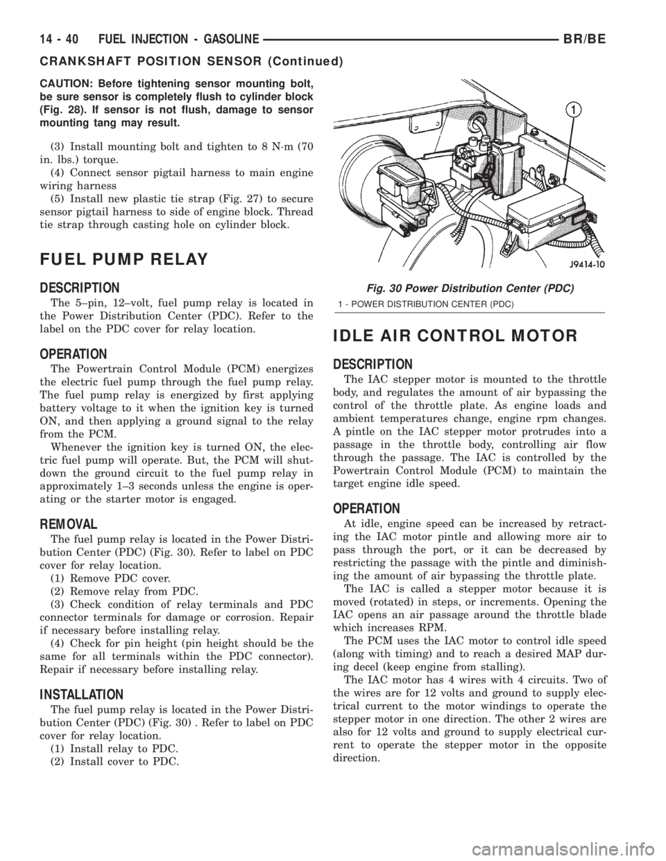
CAUTION: Before tightening sensor mounting bolt,
be sure sensor is completely flush to cylinder block
(Fig. 28). If sensor is not flush, damage to sensor
mounting tang may result.
(3) Install mounting bolt and tighten to 8 N´m (70
in. lbs.) torque.
(4) Connect sensor pigtail harness to main engine
wiring harness
(5) Install new plastic tie strap (Fig. 27) to secure
sensor pigtail harness to side of engine block. Thread
tie strap through casting hole on cylinder block.
FUEL PUMP RELAY
DESCRIPTION
The 5±pin, 12±volt, fuel pump relay is located in
the Power Distribution Center (PDC). Refer to the
label on the PDC cover for relay location.
OPERATION
The Powertrain Control Module (PCM) energizes
the electric fuel pump through the fuel pump relay.
The fuel pump relay is energized by first applying
battery voltage to it when the ignition key is turned
ON, and then applying a ground signal to the relay
from the PCM.
Whenever the ignition key is turned ON, the elec-
tric fuel pump will operate. But, the PCM will shut-
down the ground circuit to the fuel pump relay in
approximately 1±3 seconds unless the engine is oper-
ating or the starter motor is engaged.
REMOVAL
The fuel pump relay is located in the Power Distri-
bution Center (PDC) (Fig. 30). Refer to label on PDC
cover for relay location.
(1) Remove PDC cover.
(2) Remove relay from PDC.
(3) Check condition of relay terminals and PDC
connector terminals for damage or corrosion. Repair
if necessary before installing relay.
(4) Check for pin height (pin height should be the
same for all terminals within the PDC connector).
Repair if necessary before installing relay.
INSTALLATION
The fuel pump relay is located in the Power Distri-
bution Center (PDC) (Fig. 30) . Refer to label on PDC
cover for relay location.
(1) Install relay to PDC.
(2) Install cover to PDC.
IDLE AIR CONTROL MOTOR
DESCRIPTION
The IAC stepper motor is mounted to the throttle
body, and regulates the amount of air bypassing the
control of the throttle plate. As engine loads and
ambient temperatures change, engine rpm changes.
A pintle on the IAC stepper motor protrudes into a
passage in the throttle body, controlling air flow
through the passage. The IAC is controlled by the
Powertrain Control Module (PCM) to maintain the
target engine idle speed.
OPERATION
At idle, engine speed can be increased by retract-
ing the IAC motor pintle and allowing more air to
pass through the port, or it can be decreased by
restricting the passage with the pintle and diminish-
ing the amount of air bypassing the throttle plate.
The IAC is called a stepper motor because it is
moved (rotated) in steps, or increments. Opening the
IAC opens an air passage around the throttle blade
which increases RPM.
The PCM uses the IAC motor to control idle speed
(along with timing) and to reach a desired MAP dur-
ing decel (keep engine from stalling).
The IAC motor has 4 wires with 4 circuits. Two of
the wires are for 12 volts and ground to supply elec-
trical current to the motor windings to operate the
stepper motor in one direction. The other 2 wires are
also for 12 volts and ground to supply electrical cur-
rent to operate the stepper motor in the opposite
direction.
Fig. 30 Power Distribution Center (PDC)
1 - POWER DISTRIBUTION CENTER (PDC)
14 - 40 FUEL INJECTION - GASOLINEBR/BE
CRANKSHAFT POSITION SENSOR (Continued)
Page 1340 of 2255
To make the IAC go in the opposite direction, the
PCM just reverses polarity on both windings. If only
1 wire is open, the IAC can only be moved 1 step
(increment) in either direction. To keep the IAC
motor in position when no movement is needed, the
PCM will energize both windings at the same time.
This locks the IAC motor in place.
In the IAC motor system, the PCM will count
every step that the motor is moved. This allows the
PCM to determine the motor pintle position. If the
memory is cleared, the PCM no longer knows the
position of the pintle. So at the first key ON, the
PCM drives the IAC motor closed, regardless of
where it was before. This zeros the counter. From
this point the PCM will back out the IAC motor and
keep track of its position again.
When engine rpm is above idle speed, the IAC is
used for the following:
²Off-idle dashpot (throttle blade will close quickly
but idle speed will not stop quickly)
²Deceleration air flow control
²A/C compressor load control (also opens the pas-
sage slightly before the compressor is engaged so
that the engine rpm does not dip down when the
compressor engages)
²Power steering load control
The PCM can control polarity of the circuit to con-
trol direction of the stepper motor.
IAC Stepper Motor Program:The PCM is also
equipped with a memory program that records the
number of steps the IAC stepper motor most recently
advanced to during a certain set of parameters. For
example: The PCM was attempting to maintain a
1000 rpm target during a cold start-up cycle. The last
recorded number of steps for that may have been
125. That value would be recorded in the memory
cell so that the next time the PCM recognizes the
identical conditions, the PCM recalls that 125 steps
were required to maintain the target. This program
allows for greater customer satisfaction due to
greater control of engine idle.
Another function of the memory program, which
occurs when the power steering switch (if equipped),
or the A/C request circuit, requires that the IAC step-
per motor control engine rpm, is the recording of the
last targeted steps into the memory cell. The PCM
can anticipate A/C compressor loads. This is accom-
plished by delaying compressor operation for approx-
imately 0.5 seconds until the PCM moves the IAC
stepper motor to the recorded steps that were loaded
into the memory cell. Using this program helps elim-
inate idle-quality changes as loads change. Finally,
the PCM incorporates a9No-Load9engine speed lim-
iter of approximately 1800 - 2000 rpm, when it rec-
ognizes that the TPS is indicating an idle signal and
IAC motor cannot maintain engine idle.A (factory adjusted) set screw is used to mechani-
cally limit the position of the throttle body throttle
plate.Never attempt to adjust the engine idle
speed using this screw.All idle speed functions are
controlled by the IAC motor through the PCM.
REMOVAL
REMOVAL - 5.9L
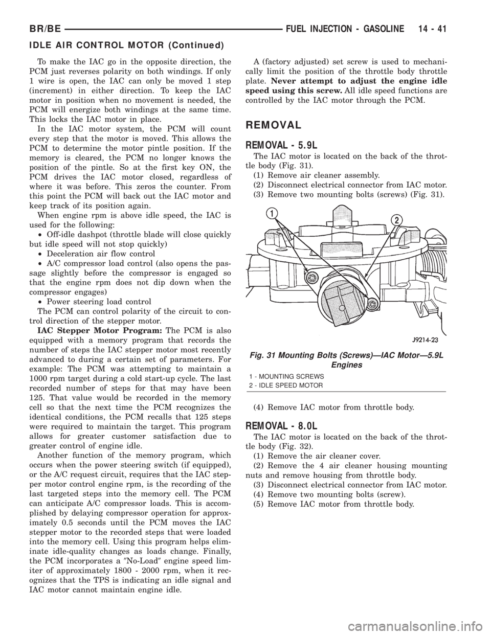
The IAC motor is located on the back of the throt-
tle body (Fig. 31).
(1) Remove air cleaner assembly.
(2) Disconnect electrical connector from IAC motor.
(3) Remove two mounting bolts (screws) (Fig. 31).
(4) Remove IAC motor from throttle body.
REMOVAL - 8.0L
The IAC motor is located on the back of the throt-
tle body (Fig. 32).
(1) Remove the air cleaner cover.
(2) Remove the 4 air cleaner housing mounting
nuts and remove housing from throttle body.
(3) Disconnect electrical connector from IAC motor.
(4) Remove two mounting bolts (screw).
(5) Remove IAC motor from throttle body.
Fig. 31 Mounting Bolts (Screws)ÐIAC MotorÐ5.9L
Engines
1 - MOUNTING SCREWS
2 - IDLE SPEED MOTOR
BR/BEFUEL INJECTION - GASOLINE 14 - 41
IDLE AIR CONTROL MOTOR (Continued)
Page 1349 of 2255
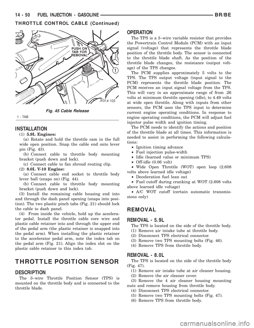
INSTALLATION
(1)5.9L Engines:
(a) Rotate and hold the throttle cam in the full
wide open position. Snap the cable end onto lever
pin (Fig. 43).
(b) Connect cable to throttle body mounting
bracket (push down and lock).
(c) Connect cable to fan shroud routing clip.
(2)8.0L V-10 Engine:
(a) Connect cable end socket to throttle body
lever ball (snaps on) (Fig. 44).
(b) Connect cable to throttle body mounting
bracket (push down and lock).
(3) Install the remaining cable housing end into
and through the dash panel opening (snaps into posi-
tion). The two plastic pinch tabs (Fig. 21) should lock
the cable to dash panel.
(4) From inside the vehicle, hold up the accelera-
tor pedal. Install the throttle cable core wire and
plastic cable retainer into and through the upper end
of the pedal arm (the plastic retainer is snapped into
the pedal arm). When installing the plastic retainer
to the accelerator pedal arm, note the index tab on
the pedal arm (Fig. 21). Align the index slot on the
plastic cable retainer to this index tab.
THROTTLE POSITION SENSOR
DESCRIPTION
The 3±wire Throttle Position Sensor (TPS) is
mounted on the throttle body and is connected to the
throttle blade.
OPERATION
The TPS is a 3±wire variable resistor that provides
the Powertrain Control Module (PCM) with an input
signal (voltage) that represents the throttle blade
position of the throttle body. The sensor is connected
to the throttle blade shaft. As the position of the
throttle blade changes, the resistance (output volt-
age) of the TPS changes.
The PCM supplies approximately 5 volts to the
TPS. The TPS output voltage (input signal to the
PCM) represents the throttle blade position. The
PCM receives an input signal voltage from the TPS.
This will vary in an approximate range of from .26
volts at minimum throttle opening (idle), to 4.49 volts
at wide open throttle. Along with inputs from other
sensors, the PCM uses the TPS input to determine
current engine operating conditions. In response to
engine operating conditions, the PCM will adjust fuel
injector pulse width and ignition timing.
The PCM needs to identify the actions and position
of the throttle blade at all times. This information is
needed to assist in performing the following calcula-
tions:
²Ignition timing advance
²Fuel injection pulse-width
²Idle (learned value or minimum TPS)
²Off-idle (0.06 volt)
²Wide Open Throttle (WOT) open loop (2.608
volts above learned idle voltage)
²Deceleration fuel lean out
²Fuel cutoff during cranking at WOT (2.608 volts
above learned idle voltage)
²A/C WOT cutoff (certain automatic transmis-
sions only)
REMOVAL
REMOVAL - 5.9L
The TPS is located on the side of the throttle body.
(1) Remove air intake tube at throttle body.
(2) Disconnect TPS electrical connector.
(3) Remove two TPS mounting bolts (Fig. 46).
(4) Remove TPS from throttle body.
REMOVAL - 8.0L
The TPS is located on the side of the throttle body
(Fig. 47).
(1) Remove air intake tube at air cleaner housing.
(2) Remove the air cleaner cover.
(3) Remove the 4 air cleaner housing mounting
nuts and remove housing from throttle body.
(4) Disconnect TPS electrical connector.
(5) Remove two TPS mounting bolts (Fig. 47).
(6) Remove TPS from throttle body.
Fig. 45 Cable Release
1-TAB
14 - 50 FUEL INJECTION - GASOLINEBR/BE
THROTTLE CONTROL CABLE (Continued)