2002 DODGE RAM lock
[x] Cancel search: lockPage 1241 of 2255
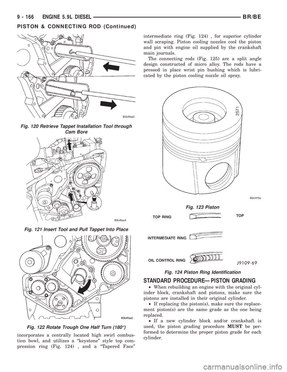
incorporates a centrally located high swirl combus-
tion bowl, and utilizes a ªkeystoneº style top com-
pression ring (Fig. 124) , and a ªTapered Faceºintermediate ring (Fig. 124) , for superior cylinder
wall scraping. Piston cooling nozzles cool the piston
and pin with engine oil supplied by the crankshaft
main journals.
The connecting rods (Fig. 125) are a split angle
design constructed of micro alloy. The rods have a
pressed in place wrist pin bushing which is lubri-
cated by the piston cooling nozzle oil spray.
STANDARD PROCEDUREÐPISTON GRADING
²When rebuilding an engine with the original cyl-
inder block, crankshaft and pistons, make sure the
pistons are installed in their original cylinder.
²If replacing the piston(s), make sure the replace-
ment piston(s) are the same grade as the one being
replaced.
²If a new cylinder block and/or crankshaft is
used, the piston grading procedureMUSTbe per-
formed to determine the proper piston grade for each
cylinder.
Fig. 120 Retrieve Tappet Installation Tool through
Cam Bore
Fig. 121 Insert Tool and Pull Tappet Into Place
Fig. 122 Rotate Trough One Half Turn (180É)
Fig. 123 Piston
Fig. 124 Piston Ring Identification
9 - 166 ENGINE 5.9L DIESELBR/BE
PISTON & CONNECTING ROD (Continued)
Page 1242 of 2255
(1) Install any of the original connecting rod and
piston assemblies into the No.1 cylinder. DO NOT
install the piston rings.
(2) Install the upper bearing shell in the connect-
ing rod with the tang of the bearing in the slot of the
connecting rod. The connecting rod bearing shell
must be installed in the original connecting rod and
cap. Use clean lubricating oil to coat the inside diam-
eter of the connecting rod bearing shell.
(3) Install the bearing shell in the connecting rod
cap with the tang of the bearing in the slot to the
cap. Use clean lubricating oil to coat the inside diam-
eter of the bearing shell.
(4) The four digit number stamped on the connect-
ing rod and cap at the parting line must match andbe installed on the oil cooler side of the engine.
Install the connecting rod cap and cap screws.
Tighten the cap screws to 35 N´m (26 ft. lbs.) torque.
(5) Use a fine grit stone to remove any burrs from
the cylinder block head deck. Zero the dial indicator
to the cylinder block head deck.
(6) Move the dial indicator directly over the piston
pin to eliminate any side-to-side movement.
(7) Rotate the crankshaft to top dead center
(TDC). Rotate the crankshaft clockwise and counter-
clockwise to find the highest dial indicator reading.
Record the reading.
(8) Remove the piston and connecting rod assem-
bly from the No.1 cylinder and install the assembly
into the No.2 cylinder. Repeat the procedure for every
cylinder using the same piston and connecting rod
assembly.
(9) Determine the grade of the piston being used
by referring to the Piston Protrusion Chart below.
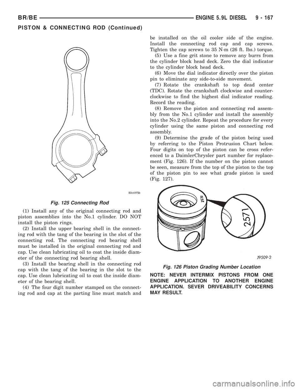
Four digits on top of the piston can be cross refer-
enced to a DaimlerChrysler part number for replace-
ment (Fig. 126). If the number on the piston cannot
be seen, measure from the top of the piston to the top
of the piston pin to see what grade piston is used
(Fig. 127).
NOTE: NEVER INTERMIX PISTONS FROM ONE
ENGINE APPLICATION TO ANOTHER ENGINE
APPLICATION. SEVER DRIVEABILITY CONCERNS
MAY RESULT.
Fig. 125 Connecting Rod
Fig. 126 Piston Grading Number Location
BR/BEENGINE 5.9L DIESEL 9 - 167
PISTON & CONNECTING ROD (Continued)
Page 1245 of 2255
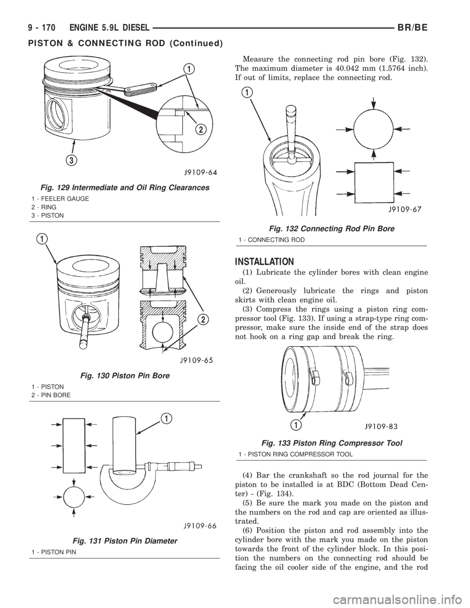
Measure the connecting rod pin bore (Fig. 132).
The maximum diameter is 40.042 mm (1.5764 inch).
If out of limits, replace the connecting rod.
INSTALLATION
(1) Lubricate the cylinder bores with clean engine
oil.
(2) Generously lubricate the rings and piston
skirts with clean engine oil.
(3) Compress the rings using a piston ring com-
pressor tool (Fig. 133). If using a strap-type ring com-
pressor, make sure the inside end of the strap does
not hook on a ring gap and break the ring.
(4) Bar the crankshaft so the rod journal for the
piston to be installed is at BDC (Bottom Dead Cen-
ter) - (Fig. 134).
(5) Be sure the mark you made on the piston and
the numbers on the rod and cap are oriented as illus-
trated.
(6) Position the piston and rod assembly into the
cylinder bore with the mark you made on the piston
towards the front of the cylinder block. In this posi-
tion the numbers on the connecting rod should be
facing the oil cooler side of the engine, and the rod
Fig. 129 Intermediate and Oil Ring Clearances
1 - FEELER GAUGE
2 - RING
3 - PISTON
Fig. 130 Piston Pin Bore
1 - PISTON
2 - PIN BORE
Fig. 131 Piston Pin Diameter
1 - PISTON PIN
Fig. 132 Connecting Rod Pin Bore
1 - CONNECTING ROD
Fig. 133 Piston Ring Compressor Tool
1 - PISTON RING COMPRESSOR TOOL
9 - 170 ENGINE 5.9L DIESELBR/BE
PISTON & CONNECTING ROD (Continued)
Page 1246 of 2255
bolt holes toward the camshaft. Use care when you
install the piston and connecting rod so the cylinder
bore is not damaged.
(7) Push the piston into the bore until the top of
the piston is approximately 50 mm (2 inch) below the
top of the block. Carefully pull the connecting rod
onto the crankshaft journal.
(8) Use clean engine oil to lubricate the threads
and under the heads of the connecting rod bolts.
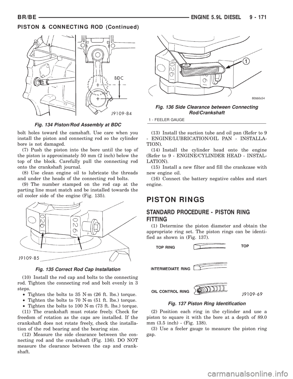
(9) The number stamped on the rod cap at the
parting line must match and be installed towards the
oil cooler side of the engine (Fig. 135).
(10) Install the rod cap and bolts to the connecting
rod. Tighten the connecting rod and bolt evenly in 3
steps.
²Tighten the bolts to 35 N´m (26 ft. lbs.) torque.
²Tighten the bolts to 70 N´m (51 ft. lbs.) torque.
²Tighten the bolts to 100 N´m (73 ft. lbs.) torque.
(11) The crankshaft must rotate freely. Check for
freedom of rotation as the caps are installed. If the
crankshaft does not rotate freely, check the installa-
tion of the rod bearing and the bearing size.
(12) Measure the side clearance between the con-
necting rod and the crankshaft (Fig. 136). DO NOT
measure the clearance between the cap and crank-
shaft.(13) Install the suction tube and oil pan (Refer to 9
- ENGINE/LUBRICATION/OIL PAN - INSTALLA-
TION).
(14) Install the cylinder head onto the engine
(Refer to 9 - ENGINE/CYLINDER HEAD - INSTAL-
LATION).
(15) Install a new filter and fill the crankcase with
new engine oil.
(16) Connect the battery negative cables and start
engine.
PISTON RINGS
STANDARD PROCEDURE - PISTON RING
FITTING
(1) Determine the piston diameter and obtain the
appropriate ring set. The piston rings can be identi-
fied as shown in (Fig. 137).
(2) Position each ring in the cylinder and use a
piston to square it with the bore at a depth of 89.0
mm (3.5 inch) - (Fig. 138).
(3) Use a feeler gauge to measure the piston ring
gap.
Fig. 134 Piston/Rod Assembly at BDC
Fig. 135 Correct Rod Cap Installation
Fig. 136 Side Clearance between Connecting
Rod/Crankshaft
1 - FEELER GAUGE
Fig. 137 Piston Ring Identification
BR/BEENGINE 5.9L DIESEL 9 - 171
PISTON & CONNECTING ROD (Continued)
Page 1248 of 2255
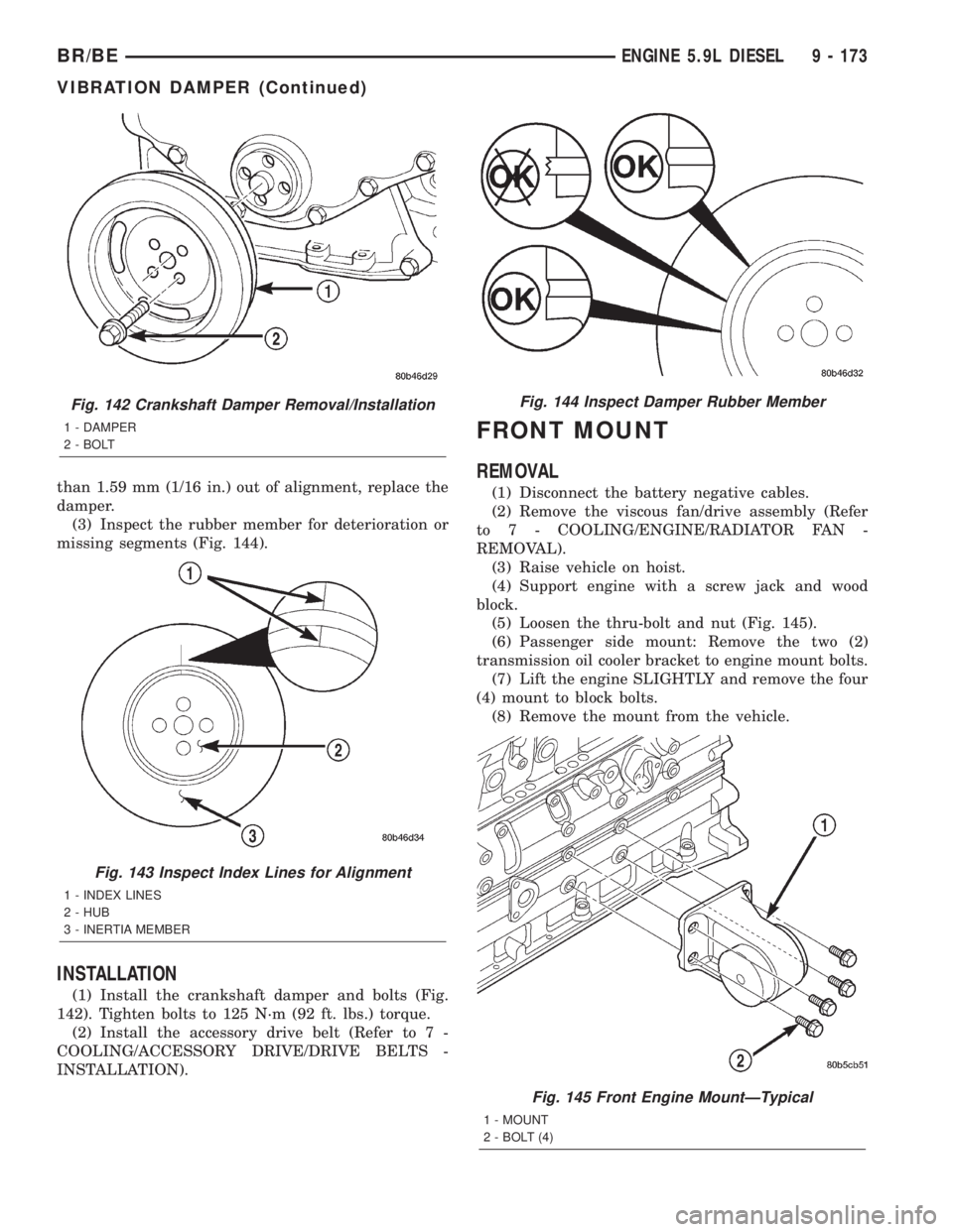
than 1.59 mm (1/16 in.) out of alignment, replace the
damper.
(3) Inspect the rubber member for deterioration or
missing segments (Fig. 144).
INSTALLATION
(1) Install the crankshaft damper and bolts (Fig.
142). Tighten bolts to 125 N´m (92 ft. lbs.) torque.
(2) Install the accessory drive belt (Refer to 7 -
COOLING/ACCESSORY DRIVE/DRIVE BELTS -
INSTALLATION).
FRONT MOUNT
REMOVAL
(1) Disconnect the battery negative cables.
(2) Remove the viscous fan/drive assembly (Refer
to 7 - COOLING/ENGINE/RADIATOR FAN -
REMOVAL).
(3) Raise vehicle on hoist.
(4) Support engine with a screw jack and wood
block.
(5) Loosen the thru-bolt and nut (Fig. 145).
(6) Passenger side mount: Remove the two (2)
transmission oil cooler bracket to engine mount bolts.
(7) Lift the engine SLIGHTLY and remove the four
(4) mount to block bolts.
(8) Remove the mount from the vehicle.
Fig. 142 Crankshaft Damper Removal/Installation
1 - DAMPER
2 - BOLT
Fig. 143 Inspect Index Lines for Alignment
1 - INDEX LINES
2 - HUB
3 - INERTIA MEMBER
Fig. 144 Inspect Damper Rubber Member
Fig. 145 Front Engine MountÐTypical
1 - MOUNT
2 - BOLT (4)
BR/BEENGINE 5.9L DIESEL 9 - 173
VIBRATION DAMPER (Continued)
Page 1249 of 2255
INSTALLATION
(1) With engine raised SLIGHTLY, position the
engine mount to the block. Install the bolts and
tighten to 149 N´m (110 ft. lbs.) torque.
(2) Install the thru-bolt into the engine mount.
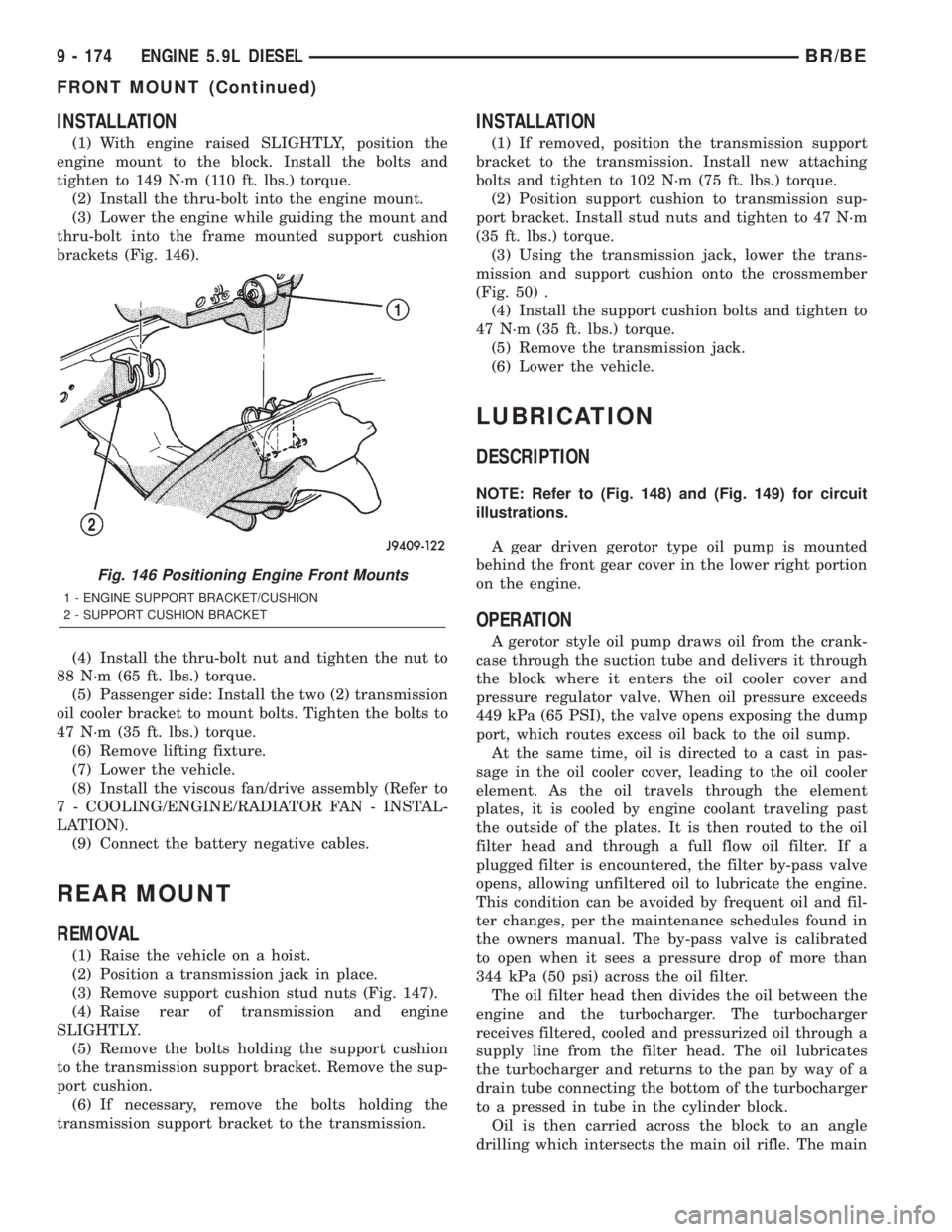
(3) Lower the engine while guiding the mount and
thru-bolt into the frame mounted support cushion
brackets (Fig. 146).
(4) Install the thru-bolt nut and tighten the nut to
88 N´m (65 ft. lbs.) torque.
(5) Passenger side: Install the two (2) transmission
oil cooler bracket to mount bolts. Tighten the bolts to
47 N´m (35 ft. lbs.) torque.
(6) Remove lifting fixture.
(7) Lower the vehicle.
(8) Install the viscous fan/drive assembly (Refer to
7 - COOLING/ENGINE/RADIATOR FAN - INSTAL-
LATION).
(9) Connect the battery negative cables.
REAR MOUNT
REMOVAL
(1) Raise the vehicle on a hoist.
(2) Position a transmission jack in place.
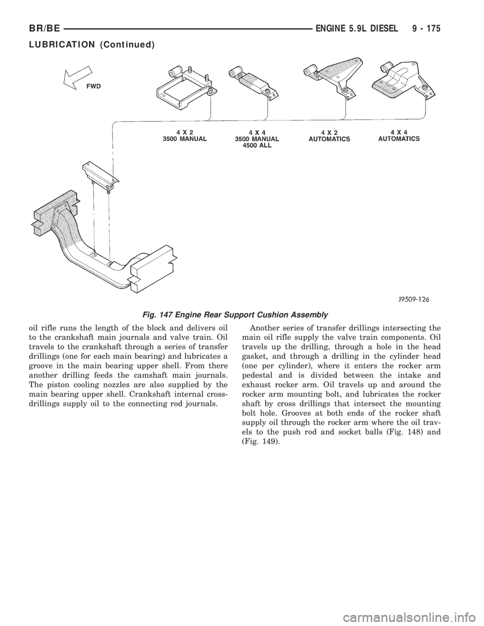
(3) Remove support cushion stud nuts (Fig. 147).
(4) Raise rear of transmission and engine
SLIGHTLY.
(5) Remove the bolts holding the support cushion
to the transmission support bracket. Remove the sup-
port cushion.
(6) If necessary, remove the bolts holding the
transmission support bracket to the transmission.
INSTALLATION
(1) If removed, position the transmission support
bracket to the transmission. Install new attaching
bolts and tighten to 102 N´m (75 ft. lbs.) torque.
(2) Position support cushion to transmission sup-
port bracket. Install stud nuts and tighten to 47 N´m
(35 ft. lbs.) torque.
(3) Using the transmission jack, lower the trans-
mission and support cushion onto the crossmember
(Fig. 50) .
(4) Install the support cushion bolts and tighten to
47 N´m (35 ft. lbs.) torque.
(5) Remove the transmission jack.
(6) Lower the vehicle.
LUBRICATION
DESCRIPTION
NOTE: Refer to (Fig. 148) and (Fig. 149) for circuit
illustrations.
A gear driven gerotor type oil pump is mounted
behind the front gear cover in the lower right portion
on the engine.
OPERATION
A gerotor style oil pump draws oil from the crank-
case through the suction tube and delivers it through
the block where it enters the oil cooler cover and
pressure regulator valve. When oil pressure exceeds
449 kPa (65 PSI), the valve opens exposing the dump
port, which routes excess oil back to the oil sump.
At the same time, oil is directed to a cast in pas-
sage in the oil cooler cover, leading to the oil cooler
element. As the oil travels through the element
plates, it is cooled by engine coolant traveling past
the outside of the plates. It is then routed to the oil
filter head and through a full flow oil filter. If a
plugged filter is encountered, the filter by-pass valve
opens, allowing unfiltered oil to lubricate the engine.
This condition can be avoided by frequent oil and fil-
ter changes, per the maintenance schedules found in
the owners manual. The by-pass valve is calibrated
to open when it sees a pressure drop of more than
344 kPa (50 psi) across the oil filter.
The oil filter head then divides the oil between the
engine and the turbocharger. The turbocharger
receives filtered, cooled and pressurized oil through a
supply line from the filter head. The oil lubricates
the turbocharger and returns to the pan by way of a
drain tube connecting the bottom of the turbocharger
to a pressed in tube in the cylinder block.
Oil is then carried across the block to an angle
drilling which intersects the main oil rifle. The main
Fig. 146 Positioning Engine Front Mounts
1 - ENGINE SUPPORT BRACKET/CUSHION
2 - SUPPORT CUSHION BRACKET
9 - 174 ENGINE 5.9L DIESELBR/BE
FRONT MOUNT (Continued)
Page 1250 of 2255
oil rifle runs the length of the block and delivers oil
to the crankshaft main journals and valve train. Oil
travels to the crankshaft through a series of transfer
drillings (one for each main bearing) and lubricates a
groove in the main bearing upper shell. From there
another drilling feeds the camshaft main journals.
The piston cooling nozzles are also supplied by the
main bearing upper shell. Crankshaft internal cross-
drillings supply oil to the connecting rod journals.Another series of transfer drillings intersecting the
main oil rifle supply the valve train components. Oil
travels up the drilling, through a hole in the head
gasket, and through a drilling in the cylinder head
(one per cylinder), where it enters the rocker arm
pedestal and is divided between the intake and
exhaust rocker arm. Oil travels up and around the
rocker arm mounting bolt, and lubricates the rocker
shaft by cross drillings that intersect the mounting
bolt hole. Grooves at both ends of the rocker shaft
supply oil through the rocker arm where the oil trav-
els to the push rod and socket balls (Fig. 148) and
(Fig. 149).
Fig. 147 Engine Rear Support Cushion Assembly
BR/BEENGINE 5.9L DIESEL 9 - 175
LUBRICATION (Continued)
Page 1254 of 2255
(3) Always check the condition of the used oil. This
can give you an indication of engine problems that
might exist.
²Thin, black oil indicates fuel dilution.
²Milky discoloration indicates coolant dilution.
(4) Clean the area around the oil filter head.
Remove the filter (Refer to 9 - ENGINE/LUBRICA-
TION/OIL FILTER - REMOVAL).
(5) Install new oil filter (Refer to 9 - ENGINE/LU-
BRICATION/OIL FILTER - INSTALLATION).
(6) Clean the drain plug and the sealing surface of
the pan. Check the condition of the threads and seal-
ing surface on the oil pan and drain plug.
(7) Install the drain plug. Tighten the plug to 50
N´m (37 ft. lbs.) torque.
(8) Use only High-Quality Multi-Viscosity lubricat-
ing oil in the Cummins Turbo Diesel engine. Choose
the correct oil for the operating conditions (Refer to
LUBRICATION & MAINTENANCE/FLUID TYPES -
DESCRIPTION).
(9) Fill the engine with the correct grade of new oil
(Refer to LUBRICATION & MAINTENANCE/FLUID
CAPACITIES - SPECIFICATIONS).
(10) Start the engine and operate it at idle for sev-
eral minutes. Check for leaks at the filter and drain
plug.
(11) Stop engine. Wait several minutes to allow the
oil to drain back to the pan and check the level
again.
USED ENGINE OIL DISPOSAL Care should be
exercised when disposing of used engine oil after
it has been drained from a vehicle's engine.
OIL COOLER & LINES
CLEANING AND INSPECTION
Clean the sealing surfaces.
Apply 483 kPa (70 psi) air pressure to the element
to check for leaks. If the element leaks, replace the
element.
OIL FILTER
REMOVAL
(1) Clean the area around the oil filter head.
Remove the filter using a 90-95 mm filter wrench.
(2) Clean the gasket surface of the filter head. The
filter canister O-Ring seal can stick on the filter
head. Make sure it is removed.
INSTALLATION
(1) Fill the oil filter element with clean oil before
installation. Use the same type oil that will be used
in the engine.
(2) Apply a light film of lubricating oil to the seal-
ing surface before installing the filter.
CAUTION: Mechanical over-tightening may distort
the threads or damage the filter element seal.
(3) Install the filter until it contacts the sealing
surface of the oil filter adapter. Tighten filter an
additional ó turn.
OIL PAN
REMOVAL
(1) Disconnect the battery negative cables.
(2) Raise vehicle on hoist.
(3) Remove transmission and transfer case (if
equipped).
(4) Remove flywheel.
(5) Disconnect starter cables from starter motor.
(6) Remove starter motor (Refer to 8 - ELECTRI-
CAL/STARTING/STARTER MOTOR - REMOVAL)
and transmission adapter plate assembly.
WARNING: HOT OIL CAN CAUSE PERSONAL
INJURY.
(7) Drain the engine oil (Refer to 9 - ENGINE/LU-
BRICATION/OIL - STANDARD PROCEDURE).
(8) Install the oil pan drain plug with a new seal-
ing washer and tighten to 60 N´m (44 ft. lbs.) torque.
(9) Remove oil pan bolts, break the pan to block
seal, and lower pan slightly and remove oil suction
tube fasteners.
(10) Remove oil pan and suction tube (Fig. 151).
CLEANING
Remove all gasket material from the oil pan and
cylinder block sealing surfaces. Extra effort may be
required around T-joint areas. Clean oil pan and
flush suction tube with a suitable solvent.
INSPECTION
Inspect the oil pan, suction tube, and tube braces
for cracks and damage. Replace any defective compo-
nent. Inspect the oil drain plug and drain hole
threads. Inspect the oil pan sealing surface for
straightness. Repair any minor imperfections with a
ball-peen hammer. Do not attempt to repair an oil
pan by welding.
BR/BEENGINE 5.9L DIESEL 9 - 179
OIL (Continued)